Generator Excitation Systems
Permanent Magnet Excited Generators
Permanent magnet pilot excited (PMPE) generators receive power for the voltage regulator from a pilot exciter, rather than the main armature as in self-excited generators. The pilot exciter consists of permanent magnet (PM) and PM armature. The pilot exciter operates independently from the generator output voltage. Constant excitation during large load application is possible, because the irregularities that occur in generator output voltage (caused by load conditions) are not fed back into the exciter. The independent operation also allows the generator to better sustain an overload for a short duration.
Self-Excited Generators
Self-Excited generators receive power for excitation and voltage sensing for the regulator from the main armature (stator) output of the generator. The voltage regulator senses the generator output voltage and provides regulated output to the generator exciter. The exciter then provides power to the main rotating field (rotor). As the main field rotates, a voltage is induced into the main armature (stator) to causes a generator output.
Copyright 1993 - 2025 Caterpillar Inc. All Rights Reserved.
Private Network For SIS Licensees.
Thu Jan 2 22:27:51 UTC+0530 2025
Product: EXCAVATOR
Model: 312B EXCAVATOR 9HR
Configuration: ISJ HEX COMMONALITY CHART 9HR00001-UP (MACHINE)
Operation and Maintenance Manual
SR4 GENERATORS AND CONTROL PANELS
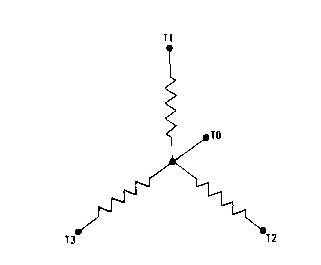
Generator Lead Connections
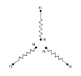
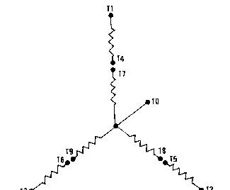
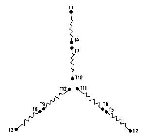
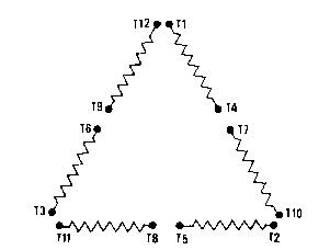
Lead Numbering
Each coil lead is marked according to the following diagrams. The diagrams contained show the four, six, ten, and twelve lead configurations available in present day SR4 generators.
The standard generator diagram and the terminal connections are on the nameplate of each generator.
Numbering is clockwise from the top and from the outside inward.
4 Lead Wye Configuration
6 Lead Wye Configuration
Terminal T4, T5 and T6 become the neutral connection when tied together in the 6 Lead Wye Configuration.
10 Lead Wye Configuration
Terminal T0 is the neutral lead for the 4 lead and 10 lead generators.
12 Lead Wye Configuration
Terminals T10, T11, and T12 become the neutral connection when tied together in the 12 Lead Wye Configuration.
12 Lead Delta Configuration
In the 12 Lead Delta Configuration Terminals T6 and T9 become the neutral connection when tied together and grounded, reflecting the Terminal T2, T10 connection as the high phase.
Grounding the Frame
In any generator set installation, the frame of the generator must be positively connected to an earth ground or to the hull of a vessel. This connection is the first one made at installation, and the last one to be removed. If the generator set is on flexible or resilient pads, the ground connection must be flexible to avoid possible breakage in later operation.
Ground connection cable or straps should have at least the current carrying capacity of the largest line lead to the connected load. Joints in cables or straps must be clean, free of electrical resistance, and
protected from possible oxidation. Bolted ground connection joints eventually oxidize, and are frequent sources of radio frequency interference. Silver soldered, bolted joints are electrically and mechanically sound.
Neutral Connections
"Y"-connected generators usually have the neutral grounded when the generator is installed unless definite measures are taken to prevent grounds on the load side. The grounding of the neutral is to prevent load side equipment damage.
If the neutral wire is grounded and one of the phase leads becomes grounded, the excessive current will open a load circuit breaker or collapse the generator voltage. The result depends on the particular generator electrical characteristics, type of fault, and circuit breaker trip rating. An undervoltage device may be required to provide adequate short circuit protection.
There are some instances in which it is undesirable to ground the neutral wire. In these applications where definite measures (ground fault protective circuits) have been taken to prevent grounds to the phase leads, an ungrounded generator neutral lead is acceptable.
Ground fault protection requires that the entire group of distribution circuits be studied and treated as a system. The owner should engage a certified and registered consultant if a new distribution system is being developed, or if an existing system is to be modified for ground fault protection.
Single Units
Four Wire: In a three phase, four wire system, the neutral wire should be grounded according to local wiring codes.
In applications where definite measures are taken to prevent grounds to the load leads, an ungrounded neutral can be used. Be sure to check your local wiring codes.
Multiple Units
Operation of multiple generators in parallel, having all neutrals grounded, may result in current circulating through the neutral connections. To eliminate the possibility of circulating currents, ground the neutral of only one generator. If multiple generators are alternated on line, a switch should be installed in the neutral ground circuit of each generator, so all but one neutral ground circuit can be opened. Be sure one neutral ground circuit is closed.
Parallel to Utility
When a Wye connected generator is to operate in parallel with a utility system (infinite bus), and the secondary of the utility system step-down transformer is also a Wye connection, grounding of both Wye neutrals may result in circulating currents through the neutrals. Plus, the coordination of a ground fault protection requires an entire system study. This study should be done by a certified and registered consultant familiar with generator systems to determine the grounding method to be used.
Product: EXCAVATOR
Model: 312B EXCAVATOR 9HR
Configuration: ISJ HEX COMMONALITY CHART 9HR00001-UP (MACHINE)
Operation and Maintenance Manual
SR4 GENERATORS AND CONTROL PANELS
Generator Performance & Options
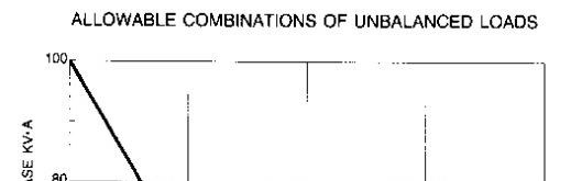
Generator Loading
When a generator is installed or reconnected, be sure the total current in one phase does not exceed the nameplate rating. Each phase should carry the same load, allowing the engine to work at its rated capacity. An electrical unbalance can result in an electrical overload and overheating if one phase exceeds the nameplate amperage.
When operating with significant single phase loads, the three phase/single phase load combinations must lie below the line on the graph.
Block Loading
Block loading is the instantaneous application of an electrical load to a generator set. This load may be anywhere from a moderate percentage of the rated load up to the rated load.
The block loading capability of a generator set depends upon engine transient response, voltage regulator response and type, altitude of operation, type of load, and the amount of load at the time the block load is applied.
If block load derating is required, refer to (International Standards Organization) ISO 3046 or SAE J1349 Standards. Also reference Engine Data Sheets, Block Loading Transient Response LEKX4066 and Transient Response LEKX4067.
Power Factor
Power factor may be thought of as the efficiency of the load - the ratio of apparent power to total power. Power factor is expressed as a decimal and denotes that portion of current supplied to a system doing useful work. The portion of current not doing useful work is absorbed in maintaining the magnetic field in motors. This current, although it is called the reactive load, does not require engine power to maintain it.
In most applications electric motors and transformers determine the power factor of the system. Induction motors usually have a 0.8 or smaller power factor. Incandescent lighting is a resistive load of about 1.0 power factor, or unity.
The power factor of a system may be determined by a power factor meter or by calculations. Determine the power requirement in kW by multiplying the power factor by the KVA supplied to the system. As the power factor goes up, the total current supplied to a constant power demand will go down. A 100 kW load at a 0.8 power factor will draw more current than a 100 kW load at 0.9 power factor. High power factor will result in full engine load at less than generator rated amperage. A lower power factor increases the possibility of overloading the generator.
NOTE: Caterpillar Generators are designed for a 0.8 power factor unless otherwise specified.
Low Idle Adjustment
Electric sets normally have a higher low idle setting than do industrial engines. Low idle will be approximately 2/3 the full load speed of 60 Hz units (4/5 full load speed of 50 Hz units).
On electric sets with some Woodward governors, there is no low idle stop. On electric sets with mechanical governors and natural gas electric sets, the low idle is set at the factory, and should only be adjusted by your Caterpillar dealer if adjustment is required.
NOTE: Operating the electric set at low idle speed for an extended time will cause some voltage regulators to shut off. The electric set must be completely shut down, and restarted to allow the voltage regulator to again produce an output.
Oilfield Generator
For SCR Controlled Electric Rigs
Oilfield generators are now available for use with SCR controlled electric oil rigs, that do not use a voltage regulator. The function of the generator control is performed by the drilling electrical control system.
Consult the drill rig builder on questions pertaining to generator control (voltage regulation, paralleling, load sharing, etc.).
Generator Options
Space Heaters
SR4 generators are available with space heaters installed for operation in high humidity conditions. For more information on space heaters, refer to the topic "Generator Maintenance" in this manual.
Embedded Temperature Detectors
SR4 generators are available with embedded temperature detectors. The detectors are installed in the slots of the main armature (stator). The detectors are used, with customer provided equipment, to measure and/or monitor the main armature winding temperature. Three types of temperature detectors are available. Contact your Caterpillar dealer for more information.
Bearing Temperature Detectors
Bearing temperature detectors are available for large frame SR4 generators. Bearing temperature detectors measure and/or monitor main bearing temperature. Bearing temperature measurements may help to prevent premature bearing failure. Two types of temperature detectors are available. Contact your Caterpillar dealer for more information. Copyright 1993 - 2025 Caterpillar Inc.
SIS
Thu Jan 2 22:27:30 UTC+0530 2025
Product: EXCAVATOR
Model: 312B EXCAVATOR 9HR
Configuration: ISJ HEX COMMONALITY CHART 9HR00001-UP (MACHINE)
Operation and Maintenance Manual
SR4 GENERATORS AND CONTROL PANELS
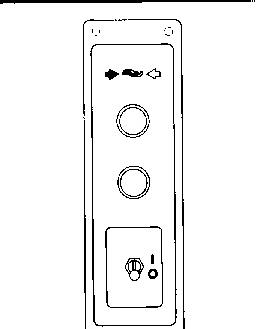
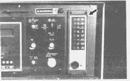
Generator Set Control Panel (103-1582 & 107-6307 If Equipped)
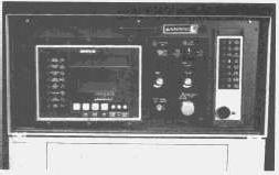
Control Panel, EMCP II
The generator set Electronic Modular Control Panel II (EMCP II) is located on top of the generator regulator housing. The control panel consists of a main panel with indicators, meters and control switches. This control panel may be equipped with optional modules to match the customers needs and requirements. The right side may be blank, or contain one of the alarm modules, or a synchronizing lights module.
The left side of the control panel contains the Generator Set Control (GSC). This is the "main" component of the system and also displays generator output, fault conditions and key engine parameters.
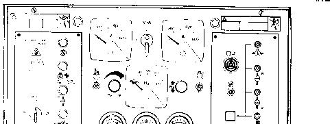
Main Control Panel
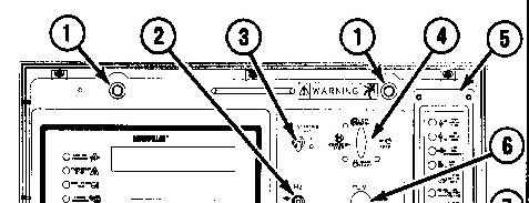
The main control panel may or may not contain all of the components shown below. Some components are optional, and may not be required for your particular application.
(1) PL; panel lights (optional).
(2) GS; governor switch or SP; speed potentiometer (optional) (GS shown).
(3) SAS; starting aid switch (optional).
(4) ECS; engine control switch.
(5) ALM; alarm module or SLM; synchronizing lights module (optional) (ALM shown).
(6) VAR; voltage adjust rheostat.
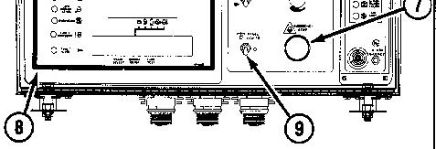
(7) ESPB; emergency stop push button.
(8) GSC; generator set control.
(9) PLS; panel light switch (optional).
* Panel lights (PL) (1) are controlled by panel lights switch (PLS) (9).
* Voltage adjust rheostat (VAR) (6), is used to adjust the generator output voltage to the desired level.
* Optional governor switch (GS) or speed potentiometer (SP) (2) is used to raise or lower the engine speed when the governor is equipped with a speed adjust motor. If the engine is equipped with an electric governor, a speed potentiometer is mounted in this location.
* Starting aid switch (SAS) (3) is used to inject ether into the engine for starting in cold weather conditions. This switch (when moved to the ON position) energizes and meters a specific amount of ether in a holding chamber. When the switch is released, the solenoid releases the ether to the engine.
* Emergency stop push button (ESPB) (7) is used to shut down the engine during an emergency situation by shutting off the fuel and activating the optional air shutoff (if equipped).
* Engine control switch (ECS) (4), determines the status of the control panel. In the Automatic position (3 o'clock), the engine will start automatically whenever the remote initiating contact is closed. The engine will shutdown after the initiating contact opens and adjustable cooldown time elapsed. The cooldown time can be programmed to give a 0 to 30 minute cooldown period before the engine shuts down.
In the Manual Run position (6 o'clock), the engine will start and run as long as the ECS switch remains in this position.
In the Stop position (9 o'clock), the fuel solenoid shuts the engine down, after a programmable cool down time period.
In the Off/Reset position (12 o'clock), the fault lights are reset and the engine shuts down immediately.
Generator Set Control (GSC)
The left side of the control panel contains the Generator Set Control (GSC). This is the "main" component of the system, and also displays generator output, generator set functions, fault conditions and key engine parameters.
The GSC accepts information from the operator, magnetic pickup, oil pressure and water temperature sensors, and optional remote sources. This information is used to determine the "on/off" state of the engine's air, fuel, and starter.
In the very basic operating conditions, the GSC receives a signal to run the generator set. The GSC turns on the engine's fuel and starter. When the engine speed reaches the crank termination speed, the starter is disengaged. When the GSC receives a signal to stop the engine, it shuts the fuel off.
* Controls normal starting and stopping of the engine.
* Shows engine conditions and generator output information on two displays. The displays also show fault codes and GSC programming information.
* Monitors the system for faults. If a fault occurs, the GSC performs a controlled fault shutdown or provides a fault alarm annunciation. The GSC uses indicators and displays to describe the fault.
* Contains programmable features for certain applications or customer requirements.
* Cycle Crank - The GSC can be programmed to crank-rest crank etc. for adjustable time periods. Refer to the Service Manual Module SENR5809 for programming instructions.
* 2301 or 2301A Control - When the engine oil pressure increases past the low oil pressure set point, the GSC will indicate to the governor that it should increase engine speed from IDLE to RATED rpm.
* Cool Down - Upon receiving a signal to perform a normal shutdown, the GSC will wait a preprogrammed amount of time before shutting the engine down by means of the fuel control.
* Automatic Operation - While in the automatic mode, the GSC can be started by a remote initiate signal (contact closure). Upon loss of the signal (contact opening), the GSC will perform a normal shutdown.
* Alarm Module Communication - The GSC can transmit fault and alarm conditions to an alarm module.
* Power Down - The Electronic Modular Control Panel II (EMCP II) system is designed to remove power from the GSC when in the off/reset mode and the proper jumper wire is removed. The GSC will not allow the power down until the crank termination relay and the fuel control relay are both "off" for about 70 seconds. If the wire is not removed, the GSC will remain powered up.
Refer to the Service Manual Module SENR5809 for the wiring diagram and jumper wire location.
* Fuel Solenoid Type - The GSC can be programmed to work with either an energized to run (ETR) fuel system or an energized to shutdown (ETS) fuel system.
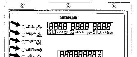
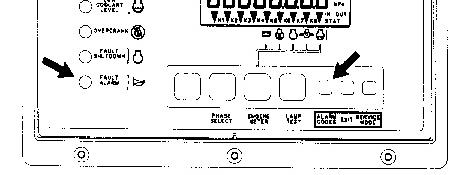
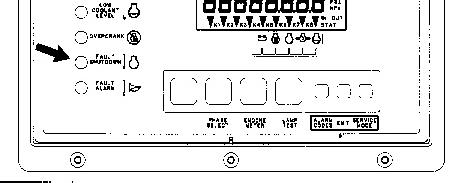
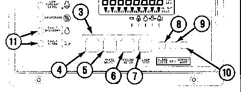
Fault Indicators
The eight fault indicators, located on the front of the GSC, are used to show and describe a fault that is present.
* The yellow fault alarm indicator FLASHES when the GSC detects a fault that is an alarm condition. The engine continues to run and start. The fault alarm indicator is accompanied by an alarm fault code that is shown on upper display when alarm codes key is pressed. Refer to SENR5809 for fault code descriptions.
* The red fault shutdown indicator FLASHES when the GSC detects a fault that is a shutdown condition. The engine is shutdown if it is running and is not allowed to start. The fault
shutdown indicator is accompanied by a diagnostic fault code that is immediately shown on upper display. Refer to SENR5809 for fault code descriptions.
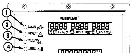
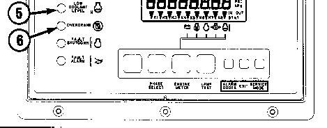
* The six red dedicated shutdown indicators represent the following shutdown conditions: low oil pressure, emergency stop, high water temperature, engine overspeed, low coolant level, and engine overcrank. When the GSC detects a fault in one of these conditions, the dedicated shutdown indicato2(that corre3ponds to the fault) FLASHES. The engine is shutdow. if it is running and is not allowed to start. There are no fault codes associated with the dedicated shutdown indicators because each indicator has an interpretive label. The conditions required for each dedicated fault and the results of each dedicated fault are as follows:
Low Oil Pressure (1) - The engine oil pressure drops below the setpoints for low oil pressure shutdown that are programmed into the GSC. There are two low oil pressure setpoints, one for when the engine is operating at idle speed and the other for when the engine is at rated speed. The low oil pressure indicator FLASHES, the engine is shutdown and is not allowed to start.
Emergency Stop (2) - The operator presses the emergency stop push button (ESPB) on the instrument panel. The emergency stop indicator FLASHES, the engine is shutdown and is not allowed to start.
High Water Temperature (3) - the engine coolant temperature rises above the setpoint for high water temperature shutdown that is programmed into the GSC. The high water temperature indicator FLASHES, the engine is shutdown and is not allowed to start.
Engine Overspeed (4) - The engine speed exceeds the setpoint for engine overspeed that is programmed into the GSC. The engine overspeed indicator FLASHES, the engine is shutdown and is not allowed to start.
Low Coolant Level (5) - The engine coolant level drops below the probe of the coolant loss sensor (optional). The engine coolant level indicator FLASHES, the engine is shutdown and is not allowed to start.
Overcrank (6) - The engine does not start within the setpoint for total cycle crank time that is programmed into the GSC. The overcrank indicator FLASHES and the engine is not allowed to start.
NOTE: The GSC can be programmed to override the shutdown for low oil pressure, high water temperature, and the low coolant level faults. When overridden, these faults are treated as alarm conditions. The corresponding dedicated shutdown indicator is ON CONTINUOUSLY (instead of flashing) and the engine continues to run and start (instead of shutting down). The dedicated shutdown indicator that is ON CONTINUOUSLY means that the setpoint for shutdown has been exceeded, but the GSC is programmed to override the shutdown condition and treat the fault as an alarm condition. As provided from the factory, the GSC treats low oil pressure, high water temperature and low coolant level as shutdowns. Refer to the Service Manual Module SENR5809 for programming procedures.
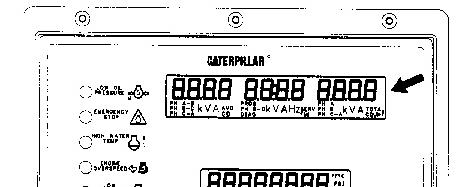
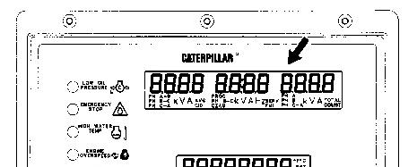
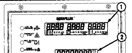
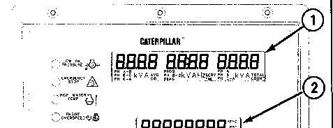
Display
Upper display (1) and lower display (2) of the GSC provide information about the generator set.
* Upper display (1) shows AC voltage, current, and frequency of one phase of the generator output. Each phase can be viewed one at a time by pushing phase select key (4). Upper display (1) is also used to show the various fault codes for system faults. For more information on fault codes, refer to the Service Manual Module SENR5809 for Fault Descriptions.
* Lower display (2) shows system battery voltage, engine hours, engine speed, engine oil pressure, and engine coolant temperature. The value for one of these conditions is shown for two seconds and then the display scrolls to the value for the next condition. A small pointer
identifies the engine condition that corresponds to the value that is showing. When engine meter key (3) is pressed, lower display (2) stops scrolling and continuously shows one particular value. Now the pointer flashes above the condition whose value is showing. When engine meter key (3) is pressed a second time, display (3) will return to scrolling.
* The relay status indicator is on the lower display also. When a GSC relay is activated, the corresponding relay indicator (K1, K2, etc.) is shown on lower display (2). When a relay is not activated, the corresponding indicator (K1, K2, etc.) is not shown. Refer to the Service Manual Module SENR5809 for a description of the relay functions.
Both displays are used for programming functions when in the service mode. For more information, refer to the Service Manual Module SENR5809 for Service Modes.
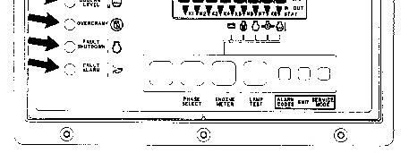
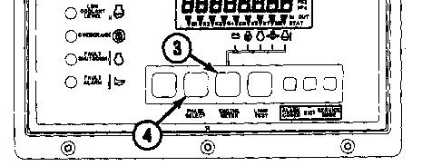
Keypad
Keypad (3) is used to control the information that is shown on upper display (1) and lower display (2). The seven keys of keypad (3) have two sets of functions, normal functions and service functions. For a description of the service functions of the keys; refer to the Service Manual Module SENR5809 for Service Modes. The normal functions of the keys are:
Leftmost Key (4) - This key only functions when the GSC is in service mode. This key is used to scroll right.
Phase Select Key (5) - Selects which phase of the generator output is displayed on the GSC. Pressing this key allows the operator to check the voltage, current, and frequency of each phase one at a time.
Engine Meter Key (6) - Stops the scrolling of engine conditions on lower display (2). Continuously shows the value for one particular engine condition. The pointer for the particular engine condition
flashes to indicate scrolling is stopped. Pressing the key again, resumes the scrolling of engine conditions.
Lamp Test Key (7) - Performs a lamp test on the GSC and the optional alarm module for a maximum of ten seconds, if held pressed. On the GSC: the eight fault indicators are ON CONTINUOUSLY, every segment of upper display (1) and lower display (2) are ON. On the optional alarm module: all of the indicators are ON and the horn sounds.
Alarm Codes Key (8) - If fault alarm indicator (11) is FLASHING, pressing this key causes upper display (1) to show the corresponding alarm fault code. Pressing this key again, resumes the showing of generator output information on upper display (1). If fault alarm indicator (4) is OFF, this key has no function. For more information on alarm fault codes, refer to the Service Manual Module SENR5809 for Fault Descriptions.
Exit Key (9) - This key only functions when the GSC is in service mode. Refer to the Service Manual Module SENR5809 for Service Modes.
Service Mode Key (10) - Pressing this key causes the GSC to enter service mode. Refer to the Service Manual Module SENR5809 for Service Modes.
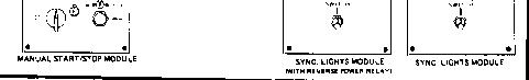
Synchronizing Lights Module (If Equipped)
The optional synchronizing lights module is mounted on the right side of the control panel. This module is not used when the control panel is equipped with the 2301A governor.
Synchronizing lights are used as an aid in paralleling units at no load and under load. Each of two lights are connected across the generator to the load side of the generator circuit breaker. Together,
they indicate when the voltages are in phase so the circuit breaker can be closed to place the generator on line with the load.
Refer to the topic "Parallel Operation" in this publication for a complete explanation on how to parallel two generators. Refer to the Service Manual Module SENR5809, for all wiring and installation information.
Synchronizing Lights Module With Reverse Power Relay (If Equipped)
The synchronizing lights module with reverse power relay is the same as the synchronizing lights module with the following exceptions:
* The reverse power relay is mounted on the control panel interior.
* A reverse power fault is indicated by the Fault Shutdown Indicator on the front of the GSC.
The reverse power relay is a single phase protective relay which is energized by power (amps-volts) in only one direction (power into generator instead of out). In a reverse power fault, the relay closes its contacts causing the engine to shutdown, taking the generator off line. The reverse power relay is equipped with a test switch and adjustments.
For additional information, refer to Service Manual Module SENR5809.
Alarm Module (If Equipped)
The alarm module (optional) is located on the right side of the control panel. The function of the alarm module is to provide a visual and audible warning of engine conditions before they become severe enough to shut the engine down or keep it from starting.
One basic alarm module is used to satisfy the requirements of standby NFPA 99 alarm module, standby NFPA 110 alarm module, NFPA 99 remote annunciator panel, and prime power alarm. This is accomplished by using different inputs to the module, and different decals on the front of the module to indicate alarms or shutdown conditions.
Refer to the Service Manual Module SENR5809, for all wiring and installation information as well as a listing of Indicators and Alarm (Horn) functions to meet NFPA requirements for your application. The front of the alarm module consists of:
* Four amber LED's which can (depending on module configuration) indicate High Coolant Temperature, Low Coolant Temperature or Low Coolant Level, Low Oil Pressure, Generator On Load, Charger Malfunction, Low Oil Level and Low Fuel Level.
* Four red LED's which can indicate a Not In Auto condition, Low DC Voltage, Air Damper Closed, Low Oil Pressure Shutdown, Overcrank Shutdown, High Coolant Temperature Shutdown, and Overspeed Shutdown.
* An audible alarm and Acknowledge/Silence switch. For more detailed information refer to the Service Manual Module SENR5809.
Product: EXCAVATOR
Model: 312B EXCAVATOR 9HR
Configuration: ISJ HEX COMMONALITY CHART 9HR00001-UP (MACHINE)
Operation and Maintenance Manual
SR4 GENERATORS AND CONTROL PANELS
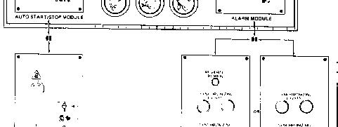
Generator Set Control Panel 4W-8000 (If Equipped)
Control Panel
The SR4 generator set control panel is located on top of the generator set. The control panel consists of a main panel with gauges, meters, and control switches. Plug in modules are utilized to enable the user to order only the components that he requires.
The left side will contain a Manual Start-Stop module or an Automatic Start-Stop module, as required by the user.
The right side may be blank or contain any of the three optional modules. The optional modules are an Alarm module, a Synchronizing Lights module, or a Synchronizing Lights With Reverse Power Relay module.
Main Control Panel
The Main Control Panel may or may not contain all of the components shown below. Some components are optional, and may not be required for your particular application.