


This is the sample of the manual click on the download link for complete manual
DOWNLOAD LINK
For some reason if link does not work download this pdf and then click

Product: TRUCK ENGINE
Model: 3126E TRUCK ENGINE HEP
Configuration: 3126E Truck Engine HEP00001-UP
Disassembly and Assembly
3126E On-highway Engine
Air Compressor Drive Gear - Remove and Install
SMCS - 1803-010-GE
Removal Procedure Table 1
Required Tools
A 1P-2320 Combination Puller 1
B 9S-1730 Socket 1
Start By:
a. Remove the air compressor.
NOTICE
Keep all parts clean from contaminants.
Contaminants may cause rapid wear and shortened component life.
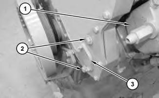
Illustration 1
g03196216
1. Temporarily install air compressor (1) with bolts (2). Remove cover plate (3).
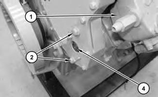
Illustration 2
g03196337
2. Loosen nut (2). Remove bolts (2) and remove air compressor (1).
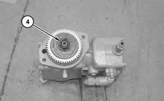
Illustration 3
3. Remove nut (4).
g03196436
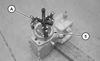
Illustration 4
g03196416
4. Use Tooling (A) in order to remove gear (5).
Installation Procedure
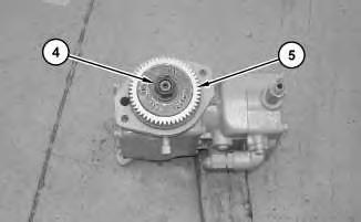
Illustration 5
g03196438
1. Clean the inside diameter of gear (5) and the shaft. Lube the washer and the shaft thread with engine oil. Position drive gear (5) on the air compressor, and install the washer and nut (4). Tighten nut (4) hand tight.
Illustration 6
g03196337
2. Install air compressor (1) and bolts (2). Keep the engine from turning and tighten nut (4) to a torque of 170 ± 15 N·m (125 ± 11 lb ft)
7
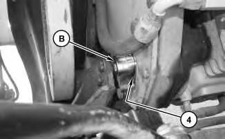
3. Install Tooling (B) onto nut (4) and tap one time a hammer.
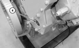
Illustration 8
4. Keep the engine from turning and tighten nut (4) to a torque of 170 ± 15 N·m (125 ± 11 lb ft)
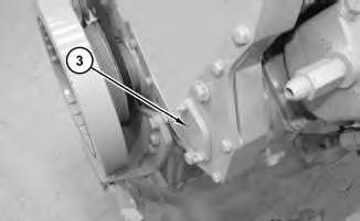
Illustration 9
5. Install cover plate (3).
End By:
a. Install the air compressor.
Copyright 1993 - 2024 Caterpillar Inc. All Rights Reserved. Private Network For SIS Licensees.
Fri May 24 12:40:47 UTC+0530 2024
Product: TRUCK ENGINE
Model: 3126E TRUCK ENGINE HEP
Configuration: 3126E Truck Engine HEP00001-UP
Disassembly and Assembly
3126E On-highway Engine
Air Compressor - Remove and Install
SMCS - 1803-010
Removal Procedure Table 1
Required Tools
A 138-7573 Link Bracket 1
Do not disconnect the air lines until the air pressure in the system is at zero. If hose is disconnected under pressure it can cause personal injury.
NOTICE
Keep all parts clean from contaminants.
Contaminants may cause rapid wear and shortened component life.
NOTICE
Care must be taken to ensure that fluids are contained during performance of inspection, maintenance, testing, adjusting, and repair of the product. Be prepared to collect the fluid with suitable containers before opening any compartment or disassembling any component containing fluids.
Refer to Special Publication, PERJ1017, "Dealer Service Tool Catalog" for tools and supplies suitable to collect and contain fluids on Cat® products.
Dispose of all fluids according to local regulations and mandates.
1. Remove the air pressure from the air tank and drain the coolant from the cooling system.
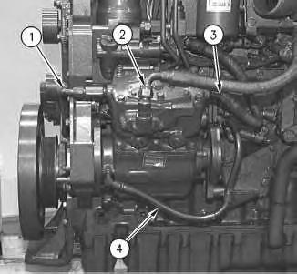
2. Disconnect water hose (1) and water hose (3) from the air compressor.
3. Disconnect air hose (2) and oil hose (4) from the air compressor.
4. Install Tooling (A) and a proper lifting device to the air compressor. The weight of the air compressor is approximately 23 kg (51 lb).
5. Remove the mounting bracket for a Midland EL-740 air compressor by using the following procedure:
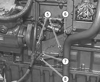
Illustration 2
a. Remove bolt (8) and the clip for the oil hose from the bracket for the air compressor.
b. Remove two bolts (5) and bolt (6) that fastens the bracket for the air compressor to the cylinder block. Remove bolt (7) and the spacer between the air compressor and the bracket for the air compressor. Remove the bracket for the air compressor.
6. Remove the mounting bracket for a Bendix Tu-Flo 550 and Bendix Tu-Flo 750 air compressors by using the following procedure:
3
Typical example
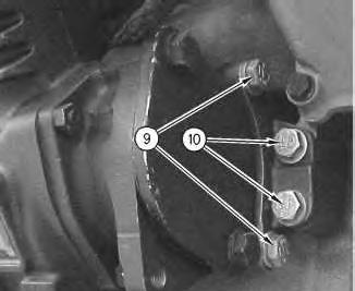
a. Remove bolts (9) that fasten the mounting bracket to the air compressor.
b. Remove bolts (10) that fasten the mounting bracket to the cylinder block. Remove the mounting bracket for the air compressor.
4
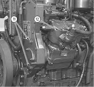
7. Remove bolts (11), air compressor (12), and the gasket from the timing gear housing.
Installation Procedure
Table 2
Required Tools
Tool Part Number Part Description Qty
A 138-7573 Link Bracket 1
NOTICE
Keep all parts clean from contaminants.
Contaminants may cause rapid wear and shortened component life.
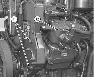
Illustration 5 g00705313
1. Install Tooling (A) and a proper lifting device to the air compressor. The weight of the air compressor is approximately 23 kg (51 lb).
2. Inspect the condition of the gasket. Replace the gasket, if necessary. Install the gasket between air compressor (12) and the timing gear housing.
3. Position air compressor (12) in the front housing. Ensure that the drive gear engages correctly with the gear in the front housing.
4. Apply 9S-3263 Thread Lock Compound to the threads of two bolts (11). Install two bolts (11). Tighten bolts (11) to a torque of 100 ± 20 N·m (75 ± 15 lb ft).
5. Install the mounting bracket for a Midland EL-740 air compressor by using the following procedure:
Illustration 6
g00609684
a. Position the bracket for the air compressor and install bolts (5) and (6). Install the spacer and bolt (7). Hand tighten all bolts.
NOTICE
A loose compressor bracket can lead to a broken front cover and can cause damage to the front gear train of the engine.
b. Tighten bolt (7) to a torque of 50 ± 10 N·m (37 ± 7 lb ft). Tighten bolt (5) to a torque of 55 ± 10 N·m (40 ± 7 lb ft). Tighten bolt (6) to a torque of 28 ± 7 N·m (21 ± 5 lb ft). Remove the lifting device and Tool (A).
6. Install the mounting bracket for Bendix Tu-Flo 550 and Bendix Tu-Flo 750 air compressors by using the following procedure:
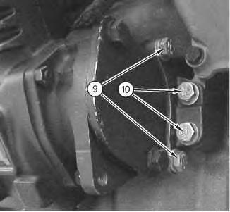
Illustration 7
Typical example
g00705242
a. Position the bracket for the air compressor and install bolts (9) and bolts (10) finger tight.
NOTICE
A loose compressor bracket can lead to a broken front cover and can cause damage to the front gear train of the engine.
b. Tighten bolts (9) to a torque of 55 ± 10 N·m (40 ± 7 lb ft). Tighten bolts (10) to a torque of 55 ± 10 N·m (40 ± 7 lb ft). Remove the lifting device and Tooling (A).
7. Connect oil hose assembly (4) to the air compressor. Connect the clip that holds the hose assembly to the air compressor. Tighten bolt (8) that holds the clip to a torque of 28 ± 7 N·m (21 ± 5 lb ft).
8. Connect water hose (1) and (3) to the air compressor.
9. Connect air hose (2) to the air compressor.
10. Fill the cooling system with coolant to the correct level. Refer to the Operation and Maintenance Manual for the correct filling procedure.
Fri May 24 12:40:29 UTC+0530 2024
Product: TRUCK ENGINE
Model: 3126E TRUCK ENGINE HEP
Configuration: 3126E Truck Engine HEP00001-UP
Disassembly and Assembly
3126E On-highway Engine
Electric Starting Motor - Remove and Install
SMCS - 1453-010
Removal Procedure
Personal injury can result from failure to disconnect the battery.
First, disconnect the negative battery cable. Then, disconnect the positive battery cable.
A positive power lead can cause sparks if the battery is not disconnected. Sparks can possibly result in battery explosion or fire.
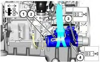
1. Disconnect cable strap (1).
2. Place an index mark on all of the harness assemblies. Disconnect the harness assemblies from electric starting motor (2).
3. Fasten a suitable lifting device to electric starting motor (4). The weight of electric starting motor (4) is approximately 35 kg (77 lb).
4. Remove bolts (3).
5. Remove electric starting motor (4) and the gasket from the flywheel housing.
Installation Procedure
1. Install electric starting motor (4) in reverse order of removal. Copyright 1993 - 2024 Caterpillar Inc.
Product: TRUCK ENGINE
Model: 3126E TRUCK ENGINE HEP
Configuration: 3126E Truck Engine HEP00001-UP
Disassembly and Assembly
3126E On-highway Engine Media
Alternator - Remove and Install
SMCS - 1405-010
Removal Procedure
Table 1
Required Tools
Tool Part Number Part Description Qty
A 168-0383 Circuit Breaker Bar 1
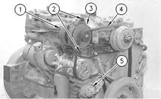
Illustration 1 g00609523
Typical Example
Note: Release the tension on the belt at the belt tightener, if the engine is not equipped with a belt tensioner.
1. Use Tooling (A) to release the tension on belt tensioner (5).
2. Remove drive belt (4) from the drive pulley on alternator (3).
3. Place an index mark on the wires of harness assembly (1) that are connected to the alternator. Disconnect harness assembly (1) from the alternator.
4. Remove bolts (2).
5. Remove alternator (3) from the mounting bracket.
Installation Procedure
Table 2
Required Tools Tool Part
A 168-0383 Circuit Breaker Bar 1
Illustration 2
Typical example
g00609523
1. Position alternator (3) on the mounting bracket. Install bolts (2).
2. Use Tooling (A) to install drive belt (4) on the drive pulley of the alternator.
Note: Adjust the tension on the drive belt if the engine is not equipped with a belt tensioner. Refer to the Operation and Maintenance Manual for the correct adjusting procedure.
3. Connect harness assembly (1) to the alternator. Use the index marks to correctly connect the harness assembly. Tighten the mounting bolt for the ground wire to a torque of 6.2 ± 0.6 N·m (54 ± 5 lb in). Tighten the mounting bolt for the battery wire to a torque of 11.3 ± 2.3 N·m (100 ± 20 lb in).
Fri May 24 12:39:56 UTC+0530 2024
Product: TRUCK ENGINE
Model: 3126E TRUCK ENGINE HEP
Configuration: 3126E Truck Engine HEP00001-UP
Disassembly and Assembly
3126E On-highway Engine
Engine Control Module - Remove and Install
SMCS - 1901-010
Removal Procedure
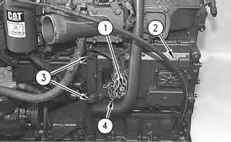
Illustration 1 g00609591
1. Loosen screw (1) until wiring harness (4) can be disconnected. Disconnect wiring harness (4) from engine control module (2).
2. Remove four bolts (3). Remove the engine control module from the engine.
Installation Procedure
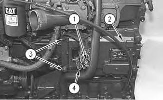
Illustration 2
1. Position engine control module (2) on the engine and install four bolts (3).
2. Connect wiring harness (4) to engine control module (2). Tighten screw (1) to a torque of 6 ± 1 N·m (53 ± 9 lb in).
Copyright 1993 - 2024 Caterpillar Inc. All Rights Reserved. Private Network For SIS Licensees. Fri May 24 12:39:42 UTC+0530 2024
Product: TRUCK ENGINE
Model: 3126E TRUCK ENGINE HEP
Configuration: 3126E Truck Engine HEP00001-UP
Disassembly and Assembly
3126E On-highway Engine
Media
Fan Drive - Install
SMCS - 1359-012
Installation Procedure
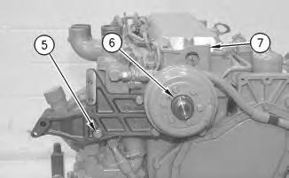
Illustration 1
g00609661
1. Position fan drive (6) and front lifting group (7) on the cylinder head assembly. Install bolts (5) and the washers.
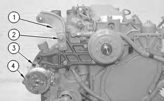
2. If equipped, position refrigerant compressor (4). Install bolts (3), the washers, and the nuts.
3. Position alternator bracket (1). Install bolts (2).
End By:
a. Install the alternator. Refer to Disassembly and Assembly, "Alternator - Remove and Install".
Copyright 1993 - 2024 Caterpillar Inc. All Rights Reserved. Private Network For SIS Licensees. Fri May 24 12:39:26 UTC+0530 2024
Product: TRUCK ENGINE
Model: 3126E TRUCK ENGINE HEP
Configuration: 3126E Truck Engine HEP00001-UP
Disassembly and Assembly
3126E On-highway Engine
Fan Drive - Remove
SMCS - 1359-011
Removal Procedure
Start By:
a. Remove the alternator. Refer to Disassembly and Assembly, "Alternator - Remove and Install".
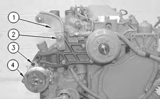
Illustration 1 g00609660
1. Remove bolts (2) and remove alternator bracket (1).
2. If equipped, remove bolts (3), the washers, and the nuts. Remove refrigerant compressor (4).
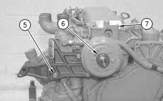
3. Remove bolts (5) and the washers. Remove fan drive (6) and front lifting group (7) from the cylinder head assembly.
Copyright 1993 - 2024 Caterpillar Inc.
All Rights Reserved.
Private Network For SIS Licensees. Fri May 24 12:39:11 UTC+0530 2024
Product: TRUCK ENGINE
Model: 3126E TRUCK ENGINE HEP
Configuration: 3126E Truck Engine HEP00001-UP
Disassembly and Assembly
3126E On-highway Engine
Fan Drive Mounting Group - Remove and Install
SMCS - 1359-010
Removal Procedure
Start By:
a. Remove the alternator. Refer to Disassembly and Assembly, "Alternator - Remove and Install".
One-Piece Fan Drive Mounting (If Equipped)
This is the sample of the manual click on the download link for complete manual
DOWNLOAD LINK
For some reason if link does not work download this pdf and then click