1. Install alternator (8) in the reverse order of removal. Copyright 1993 - 2024 Caterpillar Inc. All Rights Reserved. Private Network For SIS Licensees. Thu Aug 29 00:01:11 UTC+0530 2024
Product: EXCAVATOR
Model: 311F LRR EXCAVATOR KCW
Configuration: 311F LRR Excavator KCW00001-UP (MACHINE) POWERED BY C3.4B Engine
Disassembly and Assembly
311F LRR Excavator C3.4B Engine Supplement
Media Number -KENR9855-00
Publication Date -01/03/2014
Battery - Remove and Install
SMCS - 1401-010
Removal Procedure
1
Date Updated -05/03/2014
i05537306
Illustration
g03507102
Illustration 2
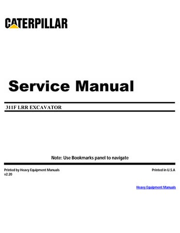
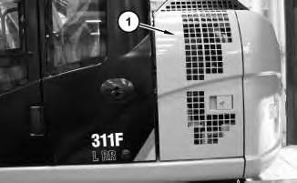
1. Open access door (1) on the left side of the machine.
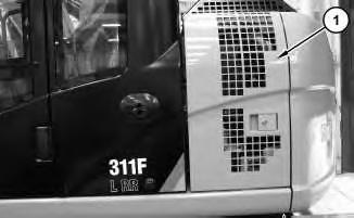
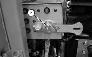
2. Turn the battery disconnect switch (2) to the OFF position. Refer to Operation and Maintenance Manual, "Battery Disconnect Switch".
1. Install batteries (9) in the reverse order of removal.
2. Turn the battery disconnect switch to the ON position. Refer to Operation and Maintenance Manual, "Battery Disconnect Switch" Copyright 1993 - 2024 Caterpillar Inc. All Rights Reserved.
Network For SIS Licensees. Thu Aug 29 00:00:44 UTC+0530 2024
Product: EXCAVATOR
Model: 311F LRR EXCAVATOR KCW
Configuration: 311F LRR Excavator KCW00001-UP (MACHINE) POWERED BY C3.4B Engine
Disassembly and Assembly
311F LRR Excavator C3.4B Engine Supplement
Media Number -KENR9855-00
Publication Date -01/03/2014
Belt Tightener - Remove and Install
SMCS - 1358-010
Removal Procedure
1. Open hood to the engine compartment.
1
g03641819
Date Updated -05/03/2014
i05726401
Illustration
2
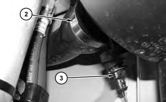
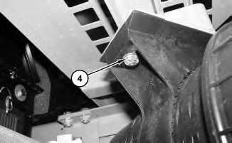
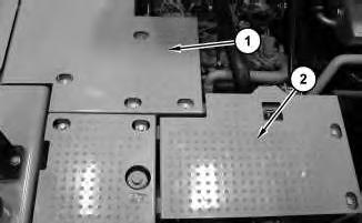
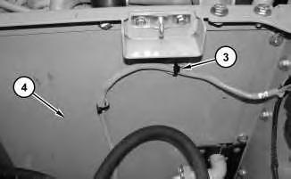
2. Remove platforms (1) and (2). Cut cable straps (3). Remove fire wall (4).
3
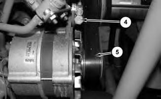
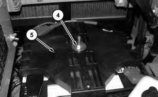
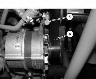
3. Release tension on adjuster bolt (5). Remove belt (6). Refer to Operation and Maintenance Manual, "Belts - Inspect/Adjust/Replace".
Illustration
g03641820
Illustration
g03641840
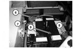
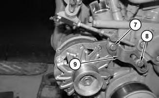
4. Remove bolts (7) and (8). Remove belt tightener (9).
Installation Procedure
1. Install belt tightener (9) in the reverse order of removal.
Copyright 1993 - 2024 Caterpillar Inc. All Rights Reserved. Private Network For SIS Licensees. Thu Aug 29 00:08:49 UTC+0530 2024
Product: EXCAVATOR
Model: 311F LRR EXCAVATOR KCW
Configuration: 311F LRR Excavator KCW00001-UP (MACHINE) POWERED BY C3.4B Engine
Disassembly and Assembly
311F LRR Excavator C3.4B Engine Supplement
Media Number -KENR9855-00
Publication Date -01/03/2014
Clean Emissions Module - Remove and Install
SMCS - 1050-010; 7279-010
Removal Procedure
1
Date Updated -05/03/2014
i05719195
Illustration
g03635470
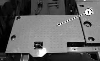
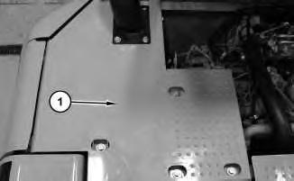
1. Open hood and remove platform (1).
Illustration 2
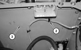
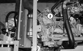
2. Remove brace (2) .
Illustration 3
g03635637
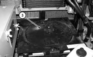
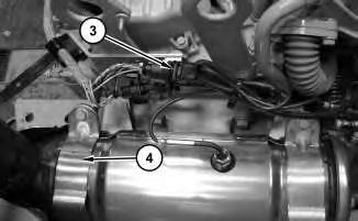
3. Disconnect harness assemblies (3). Remove the bolts and clamps (4).
Illustration 4
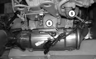
g03635684
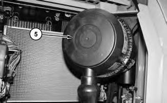
4. Remove V- band clamp (5) and clean emissions module (6).
g03635598
Installation Procedure
1. Install clean emissions module (6) in reverse order of removal.
a. Install new V- band clamp (5). Loosely align with the exhaust manifold.
b. Install clamps (4) and the bolts. Tighten the bolts evenly in three stages.
c. Tighten the bolts to an initial torque of 8 N·m (71 lb in).
d. Tighten the bolts to a second torque of 16 N·m (142 lb in).
e. Tighten the bolts to a final torque of 25 N·m (221 lb in).
f. Tighten V- band clamp to a torque of 12 N·m (106 lb in).
Copyright 1993 - 2024 Caterpillar Inc.
Rights Reserved.
Network For SIS Licensees.
Thu Aug 29 00:03:23 UTC+0530 2024
Product: EXCAVATOR
Model: 311F LRR EXCAVATOR KCW
Configuration: 311F LRR Excavator KCW00001-UP (MACHINE) POWERED BY C3.4B Engine
Disassembly and Assembly
311F LRR Excavator C3.4B Engine Supplement
Media Number -KENR9855-00
Date -01/03/2014 Date Updated -05/03/2014
Cooling System Package (Radiator, Hydraulic Oil Cooler)
Remove and Install
SMCS - 1353-010; 1353; 1374-010
Removal Procedure
Table 1
Required Tools
A 189-0408 Shackle As 1
B 439-3940 Bracket As 1
Start By:
A. Remove the hood.
B. Remove the counterweight.
C. Remove the fan.
NOTICE
Care must be taken to ensure that fluids are contained during performance of inspection, maintenance, testing, adjusting, and repair of the product. Be prepared to collect the fluid with suitable containers before opening any compartment or disassembling any component containing fluids.
Refer to Special Publication, NENG2500, "Dealer Service Tool Catalog" for tools and supplies suitable to collect and contain fluids on Cat products.
-
i05730235
Dispose of all fluids according to local regulations and mandates.
1. Drain the fluid from the hydraulic tank. Refer to Operation and Maintenance Manual, "Hydraulic System Oil - Change" for the proper draining procedure.
2. Drain the coolant. Refer to Operation and Maintenance Manual, "Coolant System Coolant (ELC) - Change" for the proper draining procedure
1
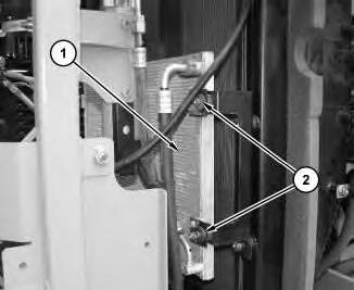
3. Remove bolts (2). Repeat for the other side of refrigerant condenser (1). Place refrigerant condenser (1) to one side.
Illustration
g01447357
2
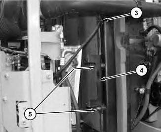
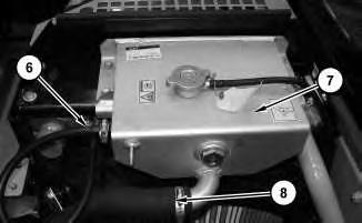
4. Cut cable strap (3). Remove bolts (5) and bracket (4). Repeat for the other side.
Illustration 3
g03642677
5. Disconnect hose (6) and (8). Remove tank assembly (7).
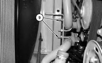
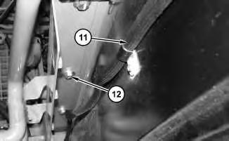
7. Remove the clamps and harness assembly (11). Remove bolts (12) and the brackets.
Illustration
g03642699
g03642689
Illustration
g03642721
7
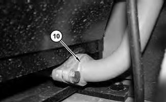
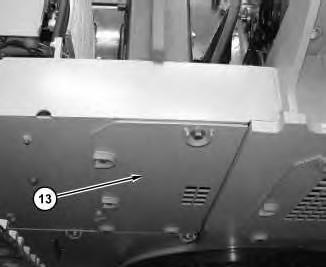
8. Remove bottom guard (13).
8
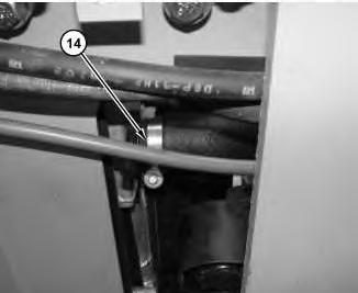
9. Disconnect hose (14).
Illustration
g03642777
Illustration
g03642779
Illustration 9
Illustration 10
Typical example of.
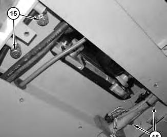
10. Remove bolts (15) and (16).
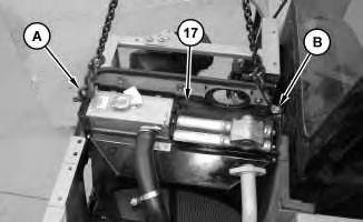
11. Attach Tooling (A), Tooling (B), and a suitable lifting device to radiator and hydraulic oil cooler (17). The weight of radiator and hydraulic oil cooler (17) is approximately 91 kg (200 lb).
Installation Procedure
1. Install radiator and hydraulic oil cooler (17) in the reverse order of removal.
Copyright 1993 - 2024 Caterpillar Inc. All Rights Reserved. Private Network For SIS Licensees. Thu Aug 29 00:09:06 UTC+0530 2024
g03642787
g03642791
Product: EXCAVATOR
Model: 311F LRR EXCAVATOR KCW
Configuration: 311F LRR Excavator KCW00001-UP (MACHINE) POWERED BY C3.4B Engine
Disassembly and Assembly
311F LRR Excavator C3.4B Engine Supplement
Media Number -KENR9855-00
Publication Date -01/03/2014
Crankshaft Pulley - Remove and Install
SMCS - 1205-010
Removal Procedure
Start By:
A. Remove fan belt.
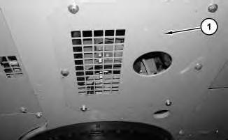
Illustration 1
1. Remove guard (1).
g03643381
Date Updated -05/03/2014
i05732193
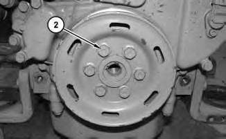
Illustration 2
2. Remove bolts (2).
g03643391
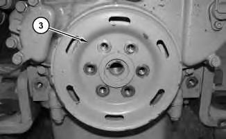
Illustration 3
3. Remove crankshaft pulley (3).
Installation Procedure
g03643387
1. Install crankshaft pulley (3) in the reverse order of removal.
a. Tighten bolts (2) to a torque of 45 N·m (33 lb ft).
Copyright 1993 - 2024 Caterpillar Inc. All Rights Reserved. Private Network For SIS Licensees. Thu Aug 29 00:09:53 UTC+0530 2024
Product: EXCAVATOR
Model: 311F LRR EXCAVATOR KCW
Configuration: 311F LRR Excavator KCW00001-UP (MACHINE) POWERED BY C3.4B Engine
Disassembly and Assembly
311F LRR Excavator C3.4B Engine Supplement
Media Number -KENR9855-00
Publication Date -01/03/2014
Electric Starting Motor - Remove and Install
SMCS - 1453-010
Removal Procedure
1. Turn the battery disconnect switch to the OFF position.
2. Open hood.
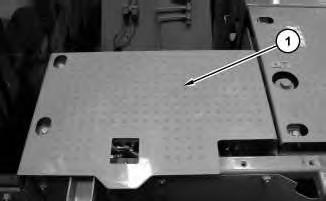
Illustration 1
3. Remove platform (1).
g03629576
Date Updated -05/03/2014
i05711889
2
4. Remove cable straps (2). Remove fire wall (3).
Illustration 3
g03629598
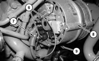
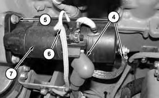
5. Disconnect cable assemblies (4). Disconnect wire harness (6). Remove bolts (5) and electric starter motor (7).
Installation Procedure
1. Install electric starter motor (7) in the reverse order of removal.
Copyright 1993 - 2024 Caterpillar Inc. All Rights Reserved. Private Network For SIS Licensees. Thu Aug 29 00:02:35 UTC+0530 2024
Illustration
g03629577
Product: EXCAVATOR
Model: 311F LRR EXCAVATOR KCW
Configuration: 311F LRR Excavator KCW00001-UP (MACHINE) POWERED BY C3.4B Engine
Disassembly and Assembly
311F LRR Excavator C3.4B Engine Supplement
Media Number -KENR9855-00
Engine - Remove and Install
SMCS - 1000-010
Removal Procedure
Table 1
Tools
Date -01/03/2014 Date Updated -05/03/2014
A 1U-9754 Hydraulic Jack 1
B 138-7573 Link Bracket 2
Start By:
A. Release the hydraulic system pressure.
B. Remove hood.
C. Remove counterweight.
Personal injury can result from contact with refrigerant.
Contact with refrigerant can cause frost bite. Keep face and hands away to help prevent injury.
Protective goggles must always be worn when refrigerant lines are opened, even if the gauges indicate the system is empty of refrigerant.
Always use precaution when a fitting is removed. Slowly loosen the fitting. If the system is still under pressure, release it slowly in a well ventilated area.
i05733393
DOWNLOAD LINK
For some reason if link does not work download this pdf and then click