DOWNLOAD LINK
For some reason if link does not work download this pdf and then click
Product: MARINE ENGINE
Model: 3116 MARINE ENGINE 1SK
Configuration: 3116 Marine Engine 1SK00001-UP
Disassembly and Assembly SUPPLEMENT FOR 3116 & 3126 MARINE ENGINE
Expansion Tank
SMCS - 1354-010
Remove & Install Expansion Tank
1. Drain the coolant from the engine into a suitable container for storage or disposal.
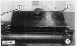
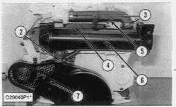
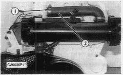
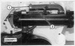
2. Remove hose clamp (1). Disconnect the hose from the fitting.
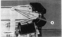
3. Remove four bolts (3).
4. Loosen the hose clamp under expansion tank (2) and remove the hose from the expansion tank. Remove the expansion tank.
NOTE: The following steps are for the installation of the expansion tank.
5. Install the hose to the bottom of expansion tank (2), then position and tighten hose clamp.
6. Position expansion tank (2), then install four bolts (3).
7. Connect the hose end to the fitting. Tighten hose clamp (1).
8. Fill the cooling system with coolant to the correct level. See the Operation & Maintenance Manual. Wed Aug 7 21:02:50 UTC+0530 2024
SENR39470030
Product: MARINE ENGINE
Model: 3116 MARINE ENGINE 1SK
Configuration: 3116 Marine Engine 1SK00001-UP
Disassembly and Assembly
SUPPLEMENT FOR 3116 & 3126 MARINE ENGINE
-SENR3947-05
Heat Exchanger
SMCS - 1379-010; 1379-017
Remove & Install Heat Exchanger
Start by:
a. remove expansion tank
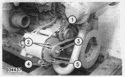
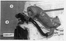
1. Loosen hose clamps (1), and disconnect the hoses.
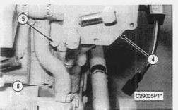
2. Loosen two hose clamps (3), then remove hose (5). Loosen hose clamp (2).
3. Remove four bolts (4) and heat exchanger (6).
NOTE: The following steps are for the installation of the heat exchanger.
SENR39470031
4. Position heat exchanger (6) and install four bolts (4).
5. Install hose (5), then tighten hose clamps (3).
6. Position rubber sleeve over pipe (7). Tighten hose clamp (2).
7. Connect the hoses over the heat exchanger pipes, and tighten hose clamps (1).
End by:
a. install expansion tank
Disassemble & Assemble Heat Exchanger
Start by:
a. remove heat exchanger
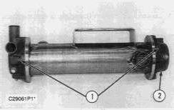
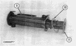
1. Remove twelve bolts and washers (1), six from each end. Remove each end bonnet assembly and the O-ring seal.
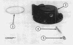
2. Remove O-ring seal (3), pipe plug (5) and rod (4) from bonnet assembly (2).
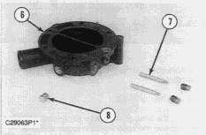
3. Remove three pipe plugs (8) and two rods (7) from exchange bonnet assembly (6).
4. Remove bundle assembly (11) and gasket (10) from shell assembly (9). Core will slide out the exchange bonnet assembly (6) end.
NOTE: The following steps are to be used to assemble the heat exchanger.
5. From exchange bonnet assembly (6) end install bundle assembly (11) and gasket (10) into shell assembly (9).
6. Apply 9S-3263 Thread Lock to the shoulder only of rods (7), then install in exchange bonnet assembly (6). Tighten to a torque of 7 ± 3 N·m (5 ± 2 lb ft).
7. Install three pipe plugs (8) into exchange bonnet (6).
8. Position bundle assembly (11), gasket (10), exchange bonnet assembly (6) and O-ring, then install six bolts (1). Tighten bolts (1) to a torque of 15 ± 3 N·m (11 ± 2 lb ft)
9. Apply 9S-3263 Thread Lock to the shoulder only of rod (4), then install the rod in bonnet assembly (2). Tighten rod to a torque of 7 ± 3 N·m (5 ± 2 lb ft)
10. Install pipe plug (5) and O-ring (3) into bonnet assembly (2).
11. Position bonnet assembly (2) and the O-ring seal onto heat exchanger. Install six bolts (1) and tighten to a torque of 15 ± 3 N·m (11 ± 2 lb ft)
End By:
a. install heat exchanger Copyright 1993 - 2024 Caterpillar Inc. All Rights Reserved. Private Network For SIS Licensees. Wed Aug 7 21:03:06 UTC+0530 2024
Product: MARINE ENGINE
Model: 3116 MARINE ENGINE 1SK
Configuration: 3116 Marine Engine 1SK00001-UP
Disassembly and Assembly
SUPPLEMENT FOR 3116 & 3126 MARINE ENGINE
Oil Cooler (Marine Transmission Gear)
SMCS - 3320-010
Remove & Install Oil Cooler (Marine Transmission Gear) (3116 Engine)
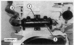
1. Loosen hose clamp (1) and remove the rubber sleeve from oil cooler (2).
2. Loosen hose clamp (3) and remove the rubber sleeve from oil cooler (2).
3. Remove four bolts (4) and remove oil cooler (2).
NOTE: The following steps are for the installation of the oil cooler.
4. Position oil cooler (2) and install bolts (4).
SENR39470033
5. Install the rubber sleeves on each end of oil cooler (2). Position and tighten hose clamps (1) and (3).
Remove & Install Oil Cooler (Marine Transmission Gear) (3126 Engine)
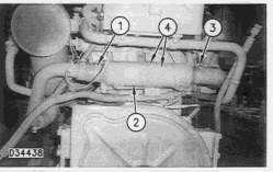
1. Loosen hose clamp (1) and remove the rubber sleeve from oil cooler (2).
2. Loosen hose clamp (3) and remove the rubber sleeve from oil cooler (2).
3. Remove four bolts (4) and remove oil cooler (2).
NOTE: The following steps are for the installation of the oil cooler.
4. Position oil cooler (2) and install bolts (4).
5. Install the rubber sleeves on each end of oil cooler (2). Position and tighten hose clamps (1) and (3).
1993 - 2024 Caterpillar Inc.
Wed Aug 7 21:03:37 UTC+0530 2024
Product: MARINE ENGINE
Model: 3116 MARINE ENGINE 1SK
Configuration: 3116 Marine Engine 1SK00001-UP
Disassembly and Assembly
SUPPLEMENT FOR 3116 & 3126 MARINE ENGINE
Raw Water Pump
SMCS - 1371-010; 1371-017
Remove & Install Raw Water Pump
3116 Engine Shown
NOTE: The procedure for removing the raw water pump on the 3116 and 3126 Marine Engines are very similar. Only one procedure will be shown.
1. Drain the coolant from the engine into a suitable container for storage or disposal.
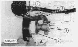
2. Loosen hose clamps (1). Remove hose (2).
3. Remove two bolts (4). Remove raw water pump (3) from the housing.
NOTE: The following steps are for the installation of the raw water pump.
4. Position gasket and raw water pump (3) on the housing. Install bolts (4).
5. Install hose (2). Tighten hose clamps (1).
6. Fill the cooling system with coolant to the correct level. See the Operation & Maintenance Manual.
SENR39470032
Disassemble & Assemble Raw Water Pump
Start by:
a. remove raw water pump
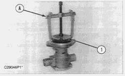
1. Remove the nut that holds the gear onto the shaft
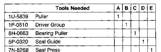
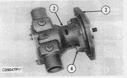
2. Remove gear (1) from the shaft with Tool (A).
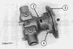
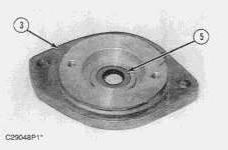
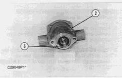
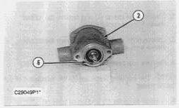
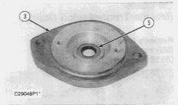
3. Remove two bolts (4), then remove plate (3) from pump housing (2).
4. Remove seal (5) from plate (3).
5. Remove snap ring (6) from pump housing (2).
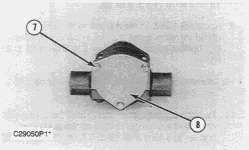
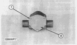
6. Remove three bolts (7), then remove plate (8).
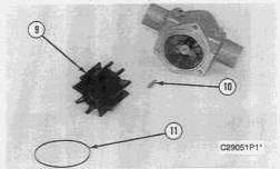
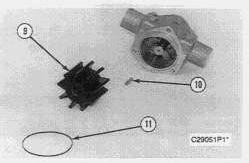
7. Remove O-ring seal (11) from housing, impeller (9) and key (10) from the shaft.
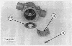
8. Remove screw (14) from side of pump housing, then remove plate (13) and brass washer (12) from inside pump.
9. Remove the snap ring and the washer from the shaft.
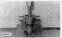
10. Place pump in press as shown.
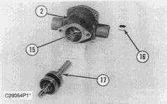
11. Press shaft (17) with attached bearings out of pump housing (2), then remove seal (16) from inside rear of pump housing (2).
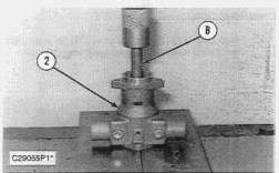
12. Place pump in press as shown. Use Tool (B) to press inner seal (15) out of pump housing (2).
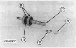
13. Remove snap ring (21) and washer (20) from shaft (17).
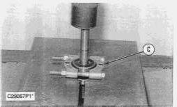
14. Place shaft (17) with bearings in a press. Press and remove bearings (18) and spacer (19) from shaft (17) using Tooling (C).
NOTE: The following steps are for the assembly of the raw water pump.
15. Press bearings (18) and spacer (19) on shaft (17), then install washer (20) and snap ring (21) on shaft (17).
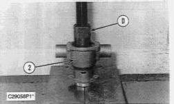
16. Position inner seal (15) in pump housing (2), then position pump housing (2) in press. Press inner seal (15) into place using Tool (D).
17. Install shaft (17) with bearings (18) and spacer (19) back into pump housing (2).
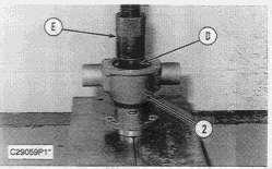
18. Position shaft seal (16) and press onto shaft (17) using Tools (D) and (E).
19. Install washer and snap ring onto shaft (17).
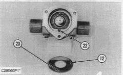
20. Position brass washer (12) into pump housing (2). Locating point (23) should be facing down and lining up with marking slot (22) in pump housing (2).
21. Install plate (13) and screw (14).
22. Install key (10) and impeller (9) onto the shaft and O-ring seal (11) onto the housing.
23. Position plate (8), and install three bolts (7).
24. Install snap ring (6) into pump housing (2).
25. Install seal (5) in plate (3).
26. Position plate (3) on pump housing (2), and install two bolts (4).
27. Install gear (1) onto the shaft, and install the nut.
End by:
a. install raw water pump
Copyright 1993 - 2024 Caterpillar Inc. All Rights Reserved.
Private Network For SIS Licensees.
Wed Aug 7 21:03:21 UTC+0530 2024
Product: MARINE ENGINE
Model: 3116 MARINE ENGINE 1SK
Configuration: 3116 Marine Engine 1SK00001-UP
Disassembly and Assembly
SUPPLEMENT FOR 3116 & 3126 MARINE ENGINE
Water Temperature Regulator Housing
SMCS - 1393-010
Remove & Install Water Temperature
Regulator Housing (3126 Engine)
1. Drain the coolant from the engine into a suitable container for storage or disposal.
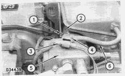
2. Loosen hose clamp (1) securing hose (2) to water temperature regulator housing (5).
3. Loosen hose clamp (4) and disconnect hose (6).
4. Disconnect wiring harness (3).
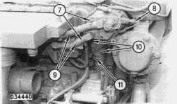
5. Loosen two hose clamps (7) and disconnect two hoses (9).
SENR39470028
6. Disconnect wiring harness (8).
7. Loosen hose clamp (11).
8. Remove two bolts (10) (one not shown) and remove water temperature regulator housing (5). Remove the gasket.
NOTE: The following steps are for the installation of the water temperature regulator housing.
9. Position water temperature regulator housing (5) and gasket, then install two bolts (10). Position and tighten hose clamp (11).
10. Connect two hoses (9) to water temperature regulator housing (5). Tighten two hose clamps (7).
11. Connect wiring harness (8).
12. Connect hose (6) and tighten clamp (4).
13. Connect wiring harness (3).
14. Make sure hose (2) is in position and tighten clamp (1).
15. Fill the cooling system with coolant to the correct level. See the Operation & Maintenance Manual.
Product: MARINE ENGINE
Model: 3116 MARINE ENGINE 1SK
Configuration: 3116 Marine Engine 1SK00001-UP
Disassembly and Assembly
SUPPLEMENT FOR 3116 & 3126 MARINE ENGINE Media
-SENR3947-05
-11/02/1997
Water Temperature Regulator Housing
SMCS - 1393-010
-09/08/2019
Remove & Install Water Temperature Regulator Housing (3116 Engine)
Start by:
a. remove expansion tank
SENR39470027
1. Loosen hose clamp (1) and disconnect hose (2) from the water temperature regulator housing.
2. Loosen four hose clamps (3) and remove hose ends from housing (4).
3. Loosen hose clamp (6). Remove two bolts (5) and remove water temperature regulator housing (4).
NOTE: The following steps are for the installation of the water temperature regulator housing.
4. Position water temperature regulator housing (4) and gasket, then install two bolts (5). Position and tighten hose clamp (6).
5. Install hose ends to housing (4), then position and tighten four hose clamps (3).
6. Install hose (2), then position and tighten hose clamp (1).
End by:
a. install the expansion tank Copyright 1993 - 2024 Caterpillar Inc.
Wed Aug 7 21:01:59 UTC+0530 2024
Product: MARINE ENGINE
Model: 3116 MARINE ENGINE 1SK
Configuration: 3116 Marine Engine 1SK00001-UP
Disassembly and Assembly
SUPPLEMENT FOR 3116 & 3126 MARINE ENGINE
Water Temperature Regulator
SMCS - 1355-010
Remove & Install Water Temperature Regulator
Start by:
a. remove expansion tank
Typical Example
1. Loosen hose clamp (1) and disconnect hose (2).
2. Remove two bolts (3), then remove regulator cover (4).
SENR39470029
3. Remove regulator (6) from housing (5).
NOTE: The following steps are for the installation of the water temperature regulator.
NOTICE
If the water temperature regulator is installed wrong it will cause the engine to overheat.
4. Position regulator (6) in housing (5) properly.
5. Position gasket and regulator cover (4), then install bolts (3).
6. Install hose (2), then tighten hose clamp (1).
End by:
a. install expansion tank
Copyright 1993 - 2024 Caterpillar Inc. All Rights Reserved. Private Network For SIS Licensees. Wed Aug 7 21:02:34 UTC+0530 2024
Product: MARINE ENGINE
Model: 3116 MARINE ENGINE 1SK
Configuration: 3116 Marine Engine 1SK00001-UP
Disassembly and Assembly
SUPPLEMENT FOR 3116 & 3126 MARINE ENGINE
Watercooled Turbocharger
SMCS - 1070-010
Remove & Install Watercooled Turbocharger (3126 Engine)
Start by:
a. remove air filter
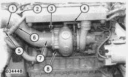
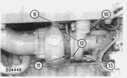
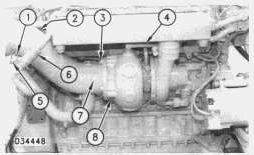
1. Loosen hose clamp (1).
2. Disconnect hose assembly (4). Cap and plug all openings immediately.
NOTE: Tooling 143-9730 and 143-9731 are required for bolt removal.
3. Remove bolt and washer (2) (not shown).
4. Remove bolt, washer and cable (5).
5. Loosen hose clamp (6).
6. Disconnect hose (8). Cap and plug all openings immediately.
7. Attach a lifting strap and a suitable lifting device to turbocharger exhaust tube (7).
8. Remove bolts and washers (3).
SENR39470026
10. Remove turbocharger exhaust tube (7). Turbocharger exhaust tube (7) weighs 24 kg (54 lb)
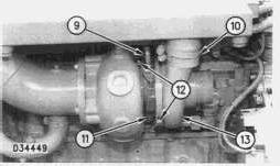
11. Remove turbocharger oil supply tube (9).
12. Remove turbocharger oil drain tube (11).
13. Loosen hose clamp (10).
14. Remove the four locknuts that hold the turbocharger to the exhaust manifold and remove turbocharger (13).
NOTE: Place alignment marks on the turbocharger cartridge and the turbocharger compressor and turbine housings. Alignment marks will be used during assembly.
NOTE: The turbocharger is serviceable at cartridge level only, or replace the complete turbocharger. Internal parts are not serviced.
15. Loosen the V-band clamps (12) and remove the turbocharger compressore and turbine housings from the turbocharger cartridge.
NOTE: The following steps are for the installation of the turbocharger.
NOTICE
Do not over tighten the turbocharger V-band clamps.
16. Install the turbocharger compressor and turbine housings to the turbocharger cartridge. Tighten the V-band clamps (12) that hold the turbocharger compressor and turbine housings to the turbocharger cartridge to a torque of 13.5 ± 0.1 N·m (119.00 ± 1.00 lb in). Tap the clamps lightly all around and tighten the V-band clamps again to 13.5 ± 0.1 N·m (119.00 ± 1.00 lb in)
17. Apply 5P-3931 Anti-Seize Compound on the threads of the turbocharger mounting studs.
18. Check the condition of the gasket used between the turbocharger and the exhaust manifold. If the gasket is damaged, use a new part for replacement.
19. Put the gasket and turbocharger (13) in position on the exhaust manifold. Install the locknuts that hold it. Tighten the locknuts to a torque of 54 ± 5 N·m (40 ± 4 lb ft).
NOTE: Check the condition of the gaskets used between the turbocharger and the oil supply and oil drain tube assemblies. If the gaskets are damaged, use new parts for replacement.
20. Install turbocharger oil drain tube (11).
21. Install turbocharger oil supply tube (9).
22. Tighten hose clamp (10).
23. Connect hose assembly (4).
24. Connect hose (8) and tighten the clamp.
25. Attach a lifting strap and a suitable lifting device to turbocharger exhaust tube (7). Install turbocharger exhaust tube (7) in its original position and secure with bolts (3). Turbocharger exhaust tube (7) weighs 24 kg (54 lb)
26. Tighten hose clamp (6).
27. Install bolt and washer (2) (not shown).
28. Tighten hose clamp (1).
29. Install cable (5), washer and bolt. End by:
a. install air filter
Product: MARINE ENGINE
Model: 3116 MARINE ENGINE 1SK
Configuration: 3116 Marine Engine 1SK00001-UP
Disassembly and Assembly
SUPPLEMENT FOR 3116 & 3126 MARINE ENGINE
Watercooled Turbocharger
SMCS - 1070-010
Remove & Install Watercooled Turbocharger (3116 Engine)
Start by:
a. remove air filter
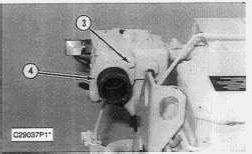
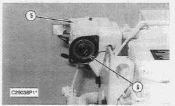
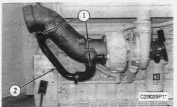
1. Remove two hose clamps (1) and pipe assembly (2) from the turbocharger exhaust tube.
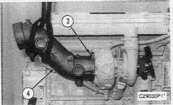
2. Install a strap around turbocharger exhaust tube (4) and remove five bolts (3). Remove turbocharger exhaust tube (4). Exhaust tube (4) weighs 24 kg (54 lb)
SENR39470025