



Note: Use Bookmarks panel to navigate

Product: MINI HYD EXCAVATOR
Model: 308 MINI HYD EXCAVATOR GG8
Configuration: 308 CR Mini Hydraulic Excavator GG800001-UP (MACHINE) POWERED BY C3.3B Engine
Disassembly and Assembly
307.5, 308, 308.5, 309, and 310 Mini Hydraulic Excavator Machine Systems
Media Number -M0095130-08 Publication Date -01/10/2020 Date Updated -06/10/2020
Accumulator - Remove and Install
SMCS - 4263-010; 4331-010; 5077-010; 7336-010
S/N - GG81-UP
S/N - GG91-UP
S/N - GK81-UP
S/N - GW71-UP
S/N - GW81-UP
S/N - GW91-UP
S/N - GWT1-UP
S/N - GX81-UP
Removal Procedure
Table 1
Required Tools
Tool Part Number Part Description Qty
A 311-1362 Vacuum Gauge Gp 1
1. Release the hydraulic system pressure. Refer to Operation and Maintenance Manual, "System Pressure - Release."
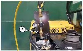
2. Install Tooling (A) onto the hydraulic tank. Attach an air supply hose onto Tooling (A). Apply 138 kPa (20 psi) to pull a vacuum on the hydraulic system.
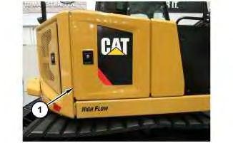
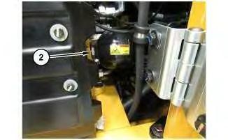
Installation Procedure
1. Install accumulator (2) in the reverse order or removal.
Copyright 1993 - 2023 Caterpillar Inc. All Rights Reserved. Private Network For SIS Licensees.
Fri Oct 27 02:13:56 UTC+0530 2023
Product: MINI HYD EXCAVATOR
Model: 308 MINI HYD EXCAVATOR GG8
Configuration: 308 CR Mini Hydraulic Excavator GG800001-UP (MACHINE) POWERED BY C3.3B Engine
Disassembly and Assembly
307.5, 308, 308.5, 309, and 310 Mini Hydraulic Excavator Machine Systems
Media Number -M0095130-08 Publication Date -01/10/2020 Date Updated -06/10/2020
Actuator Motor (Water Valve) - Remove and Install
SMCS - 7304-010-MQ
Removal Procedure
NOTICE
Care must be taken to ensure that fluids are contained during performance of inspection, maintenance, testing, adjusting, and repair of the product. Be prepared to collect the fluid with suitable containers before opening any compartment or disassembling any component containing fluids.
Refer to Special Publication, PERJ1017, "Dealer Service Tool Catalog" for tools and supplies suitable to collect and contain fluids on Cat® products.
Dispose of all fluids according to local regulations and mandates.
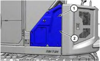
Illustration 1 g06455132
1. Remove bolts (1) and cover assembly (2).
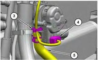
Illustration 2
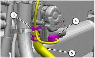
2. Remove cable strap (3) and disconnect harness assembly (4).
3. Disconnect hose (5).
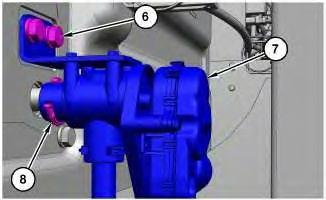
Illustration 3
4. Remove clip (8).
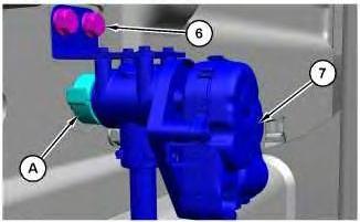
5. Remove bolts (6) and actuator valve (7).
g06455134
This is the sample of the manual click on the download link for complete manual
DOWNLOAD LINK
For some reason if link does not work download this pdf and then click
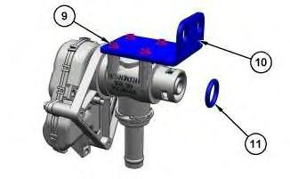
Illustration 4
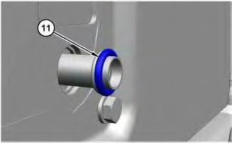
6. Remove O-ring seal (11).
g06455135
7. Remove screws (9) and mounting plate (10).
Installation Procedure
Table 1
Required Tools
A 465-7614 Clip 1
B - Silicone Dielectric lubricant -
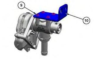
Illustration 5
g06455179
1. Install mounting plate (10) and screws (9).
6
2. Apply Tooling (B) to O-ring seal (11). Install O-ring seal (11) onto the conditioner tube.
7
3. Install Tooling (A) onto actuator valve (7). Install actuator valve (7).
4. Install bolts (6). Tighten bolts (6) to a torque of 15 ± 3 N.m (133 ± 27 lb in).
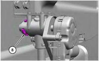
Illustration 8
5. Remove Tooling (A) and install clip (8).
9
6. Connect hose (5).
7. Connect harness assembly (4) and install cable strap (3).
Illustration 10
8. Install cover assembly (2) and bolts (1).
Copyright 1993 - 2023 Caterpillar Inc. All Rights Reserved. Private Network For SIS Licensees. Fri Oct 27 01:37:03 UTC+0530 2023
Product: MINI HYD EXCAVATOR
Model: 308 MINI HYD EXCAVATOR GG8
Configuration: 308 CR Mini Hydraulic Excavator GG800001-UP (MACHINE) POWERED BY C3.3B Engine
Disassembly and Assembly
307.5, 308, 308.5, 309, and 310 Mini Hydraulic Excavator Machine Systems
Media Number -M0095130-08 Publication Date -01/10/2020 Date Updated -06/10/2020
Blower Motor (Air Conditioner, Heater) - Remove and Install
SMCS - 7304-010-BW; 7309-010-BW; 7320-010-BW
S/N - GG81-UP
S/N - GG91-UP
S/N - GK81-UP
S/N - GW71-UP
S/N - GW81-UP
S/N - GW91-UP
S/N - GWT1-UP
S/N - GX81-UP
Removal Procedure
Start By:
a. Remove the hydraulic lockout control
b. Remove the joystick control assembly
c. Remove the seat
1. Turn the battery disconnect switch to the OFF switch.
5.
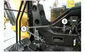
1
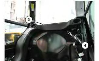
4
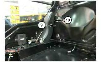
6. Remove screw (9) and duct (10).
5
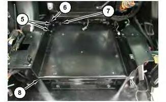
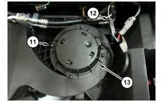
7. Remove four screws (11).
8. Disconnect harness assemblies (12).
9. Remove blower motor (13).
Installation Procedure
1. Install blower motor (13) in the reverse order of removal. Copyright 1993 - 2023 Caterpillar Inc.
Product: MINI HYD EXCAVATOR
Model: 308 MINI HYD EXCAVATOR GG8
Configuration: 308 CR Mini Hydraulic Excavator GG800001-UP (MACHINE) POWERED BY C3.3B Engine
Disassembly and Assembly
307.5, 308, 308.5, 309, and 310 Mini Hydraulic Excavator Machine Systems
Boom - Remove and Install
SMCS - 6501-010
Removal Procedure Table 1
Required Tooling
Start By:
Personal injury can result from hydraulic oil pressure and hot oil.
Hydraulic oil pressure can remain in the hydraulic system after the machine has been stopped. Serious injury can be caused if this pressure is not released before any service is done on the hydraulic system.
Make sure all the attachments have been lowered, and the oil is cool, before removing any components or lines. Remove the oil filler cap only when the filler cap is cool enough to touch with your bare hand.
a. Remove the stick cylinder.
b. Remove the stick.
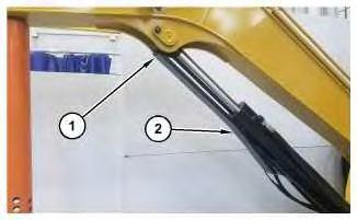
Illustration 1
1. Remove bolt (1) and guard (2).
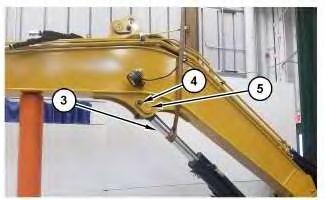
Illustration 2
g06415502
2. Attach a suitable lifting device to the rod end of boom cylinder (3).
3. Remove bolt (4) and pin assembly (5).
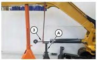
Illustration 3
4. Lower the rod end of the boom cylinder (3) onto Tooling (A).
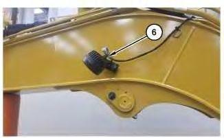
Illustration 4
g06415582
5. Disconnect harness assembly (6). Repeat for the opposite side of the boom.
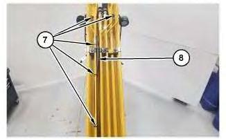
Illustration 5
6. Cut cable straps (7).
g06415646
7. Position harness assembly (8) out of the way.
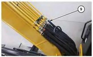
Illustration 6
g06415666
Note: Note the orientation of hose assemblies (9) for installation purposes.
8. Disconnect hose assemblies (9).
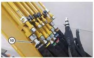
Illustration 7
Note: Note the orientation of hose assemblies (10) for installation purposes.
9. Disconnect hose assemblies (10).
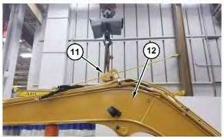
Illustration 8
g06415880
10. Attach a suitable lifting device to pin assembly (11) on top of boom (12).
The weight of the boom is approximately 458 kg (1010 lb).
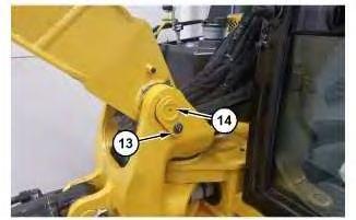
Illustration 9 g06415882
Note: Note the number of shims for installation purposes.
11. Remove bolt (13), pin assembly (14), and the shims.
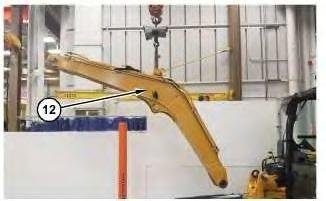
Illustration 10 g06415883
12. Remove boom (12).
Installation Procedure
1. Install boom (12) in the reverse order of removal.
a. Install the shims as required to adjust lateral clearance to 0.6 mm (0.024 inch).
b. Coat all bores and sealing lips with Tooling (B) prior to assembly. After assembly lubricate all joints from the joint fittings.
1993 - 2023 Caterpillar Inc.
Fri Oct 27 01:28:28 UTC+0530 2023
Product: MINI HYD EXCAVATOR
Model: 308 MINI HYD EXCAVATOR GG8
Configuration: 308 CR Mini Hydraulic Excavator GG800001-UP (MACHINE) POWERED BY C3.3B Engine
Disassembly and Assembly
307.5, 308, 308.5, 309, and 310 Mini Hydraulic Excavator Machine Systems
Media Number -M0095130-08
Boom Cylinder - Assemble
SMCS - 5456-016
Assemble
Table 1
Required Tools
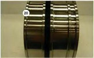
Illustration 1
1. Install O-ring seal (20).
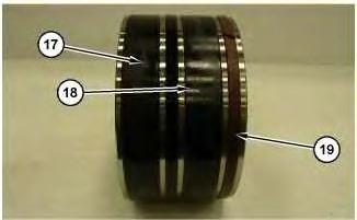
2
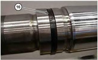
3
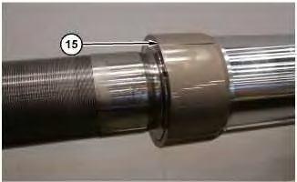
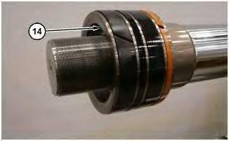
Illustration 5
5. Install piston (14).
6
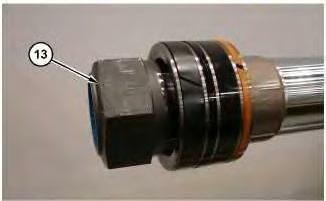
Install nut (13)
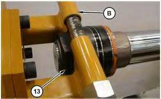
7
7. Use Tooling (B) to tighten nut (13). Refer to Table 2 for the correct torque specification.
This is the sample of the manual click on the download link for complete manual
DOWNLOAD LINK
For some reason if link does not work download this pdf and then click