

307 EXCAVATOR

Product: EXCAVATOR
Model: 307 EXCAVATOR 2WM
Configuration: 307 Excavator 2WM00500-UP (MACHINE) POWERED BY 3054 Engine
Disassembly and Assembly
JF Series Starting Motor
Media Number -SENR3550-01 Publication Date -01/09/2000
General Information
SMCS - 1453
Updated -09/10/2001
The following diagrams are intended to aid in the disassembly and assembly of the starting motor.
i01369282
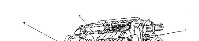
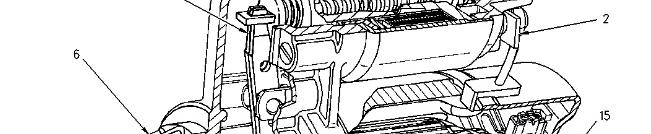
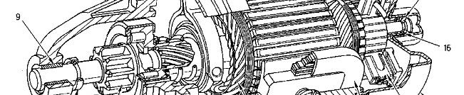
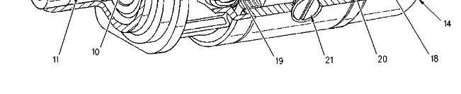
Illustration 1
Starting motor
g00719544
(1) Solenoid assembly
(2) Field windingstrap
(3) Solenoid plunger
(6) Drive housingassembly
(7) Shift leverassembly
(9) Drive housingbushing
(10) Pinion drive assembly
(11) Seal
(14) End cover assembly
(15) C washer
(16) Shims
(18) Brushholderassembly
(19) Armature assembly
(20) Field winding assembly
(21) Screws

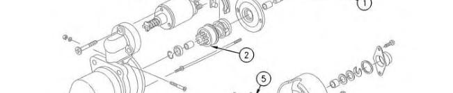

Illustration 2
Starting motor
(1) Armature assembly
(2) Pinion drive assembly
(3) Solenoid assembly
(4) Shift leverassembly
(5) Brush holder
g00731810
(6) Brush springs
(7) Brushes
(8) Excitation winding Copyright 1993 - 2020 Caterpillar Inc. All Rights Reserved. Private Network For SIS Licensees. Sun Sep 27 13:50:21 UTC+0530 2020
This is the sample of the manual click on the download link for complete manual
DOWNLOAD LINK
For some reason if link does not work download this pdf and then click
Product: EXCAVATOR
Model: 307 EXCAVATOR 2WM
Configuration: 307 Excavator 2WM00500-UP (MACHINE) POWERED BY 3054 Engine
Disassembly and Assembly
Starting Motor - Assemble
SMCS - 1453-016
Assembly Procedure
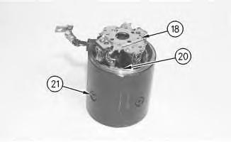
Illustration 1
g00718908
1. Position the field winding assembly (20) within the starter motor housing. Put Thread Lock Compound in the threads of the screws(21). Install the screws and tighten the screws to a torque of 36 to 53 N·m (27 to 39 lb ft).
2. Solder the two negative brush leadsto the brush holder assembly (18) if the brush leads were removed. Put the brush holder assembly (18) in position on the starting motor housing. Install the two positive brushes to the field winding leads. Solder the two positive brushes to the field winding leads.
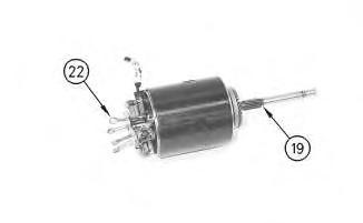
Illustration 2 g00718909
3. Put the armature assembly (19) in position in the starting motor housing. Use the cotter pins (22) to hold the brushes against the brush springs until the commutator is under the brushes.
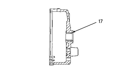
Illustration 3 g00719542
4. Install the bushing (17) into the end cover with the driver group.
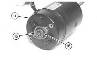
Illustration 4
5. Put the end cover assembly (14) in position on the starting motor housing.
6. Install the shims (16). Install the C washer (15) .
7. Put Molybdenum Grease on the ends of the armature. Put Molybdenum Grease in the center cover. Install the seal and install the center cover. Put Thread Lock Compound on the threadsof the two screws. Install the screws. Tighten the screws to a torque of 9 to 11 N·m (80 to 97 lb in).
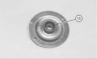
Illustration 5
8. Install the bushing into the bearing assembly with the driver group, if necessary. Install the seal (13) into the bearing assembly with the driver group.
g00718901
g00718899
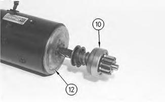
Illustration 6
g00718911
9. Install the bearing assembly (12) over the armature.
10. Put the pinion drive assembly (10) in position on the armature.
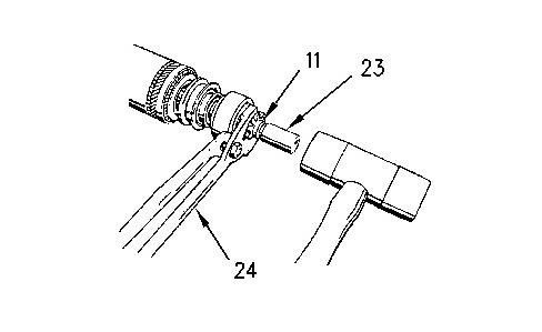
Illustration 7
g00719548
11. Put the seal (11) on the armature shaft. Put the ring in the armature ring slot. Do not scratch the armature shaft. Use multiple position pliersto press the ends of the ring together in the slot. Push a suitable assembly sleeve (23) onto the armature shaft against the ring.
12. Turn the pinion drive assembly (10) and the seal (11) against the ring. Use multiple position pliers (24) to secure the assembly in position. Engage the ring under the seal (11) by hammering against the sleeve (23), asshown. Use a plastic hammer or a rubber hammer.
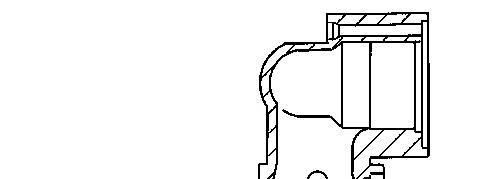


Illustration 8 g00719540
13. Install the bushing (9) into the drive housing with the driver group, if necessary.
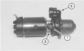
Illustration 9 g00718897
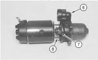
14. Position one of the studs(8) into the starting motor housing. Put the shift lever assembly (7) in position on the pinion drive housing.
15. Put the seal and the other stud into the drive housing assembly (6). Put the drive housing assembly over the pinion drive assembly by aligning the marks. At the same time, feed the shift lever assembly (7) into the drive housing.
16. Install stud (8) into the drive housing. Push everything together with studs through the holes in the end cover assembly.
10
17. Put Thread Lock Compound on the threads of the studs. Install the washersand the nuts (5). Tighten the nuts to a torque of 9.1 to 12.2 N·m (80.5 to 108 lb in).
18. Put Thread Lock Compound on the shift lever screw. Install the screw through the drive housing and through the shift lever. Install the washer and install the nut (4). Tighten the nut to a torque of 3.2 to 4.0 N·m (28 to 35 lb in).
11
Illustration
g00718894
Illustration
g00718912
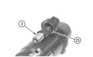
19. Compress the spring (25) against the shift lever until the shift lever goes into the slot of the solenoid plunger (3) .
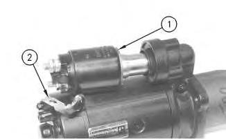
Illustration 12
20. Put solenoid assembly (1) in position over the solenoid plunger. Put Thread Lock Compound on the threads of the three solenoid screws. Install the solenoid screws through the drive housing assembly and into the solenoid assembly (1). Tighten the screws to a torque of 4.6 to 6.0 N·m (41 to 53 lb in) .
21. Connect the field winding strap (2) to the solenoid assembly. Tighten the motor terminal nut to a torque of 28 ± 4 N·m (21 ±3 lb ft) .
22. Check the armature end play.
g00718914
Product: EXCAVATOR
Model: 307 EXCAVATOR 2WM
Configuration: 307 Excavator 2WM00500-UP (MACHINE) POWERED BY 3054 Engine
Disassembly and Assembly
Starting Motor - Disassemble
SMCS - 1453-015
Disassembly Procedure
Remove the starting motor from the machine. The procedure for removal of the starting motor may vary slightly with a different series of starting motor.
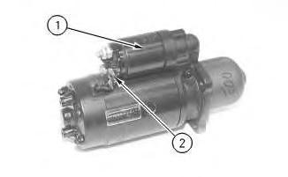
Illustration 1 g00718892
1. Disconnect the field winding strap (2) from the solenoid assembly (1) .
2
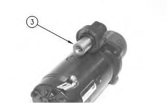
2. Disconnect the solenoid plunger and remove the solenoid plunger (3) from the shift lever. To remove the plunger, lift the plunger slightly.
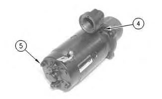
Illustration 3
g00718894
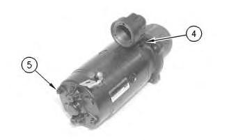
3. Scribe a line on the drive and the starting motor housings for proper alignment at assembly. Remove the end cover nuts (5) and the washers. Remove the shift lever nut (4), the washer, and the screw.
Illustration
g00718893
4
4. Separate the two halves of the starting motor. It may be necessary to remove one stud (8) from the drive housing in order to remove the shift lever assembly (7) and drive housing assembly (6). Do not damage the seal.

Illustration 5 g00719540
Illustration
g00718897
5. If necessary, remove the bushing (9) from the drive housing.
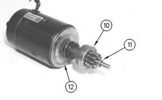
Illustration 6
g00718898
6. Remove the seal (11) from the ring with a suitable sleeve. Remove the ring, the seal (11), and the pinion drive assembly (10) from the armature.
7. Remove the bearing assembly (12) .
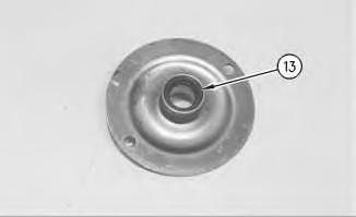
Illustration 7
g00718899
8. Remove the seal (13) and remove the bushing from the bearing assembly, if necessary.
Illustration 8 g00718901
9. Remove the two screws and the center cover from the end cover assembly. Remove the seal.
10. Remove the C washer (15) from the end of the armature. Remove the shims(16) from the end of the armature.
11. Remove the end cover assembly (14) .


Illustration 9 g00719542
12. Remove the bushing (17) from the end cover, if necessary.
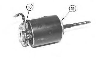
Illustration 10
13. Remove the armature assembly (19) from the starting motor housing and the brush holder assembly (18) .
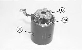
Illustration 11
g00718908
14. Unsolder the field winding leads from the positive brush leads. Remove the brush holder assembly (18). Unsolder the negative brushesfrom the brush holder, if necessary.
15. Remove the screws (21) from the starting motor housing. Remove the field winding assembly (20) from the starting motor housing. Use an impact driver to remove the screws (21), if necessary.
NOTICE
Do not use a liquid cleaning agent to cleanthe armature assembly, field winding (coil) assembly, or pinion drive assembly. Liquids can damage these parts. Use only compressedair to clean them.
g00718902
Personal injury can result from air pressure.
Personal injury can result without following proper procedure. When using pressure air, wear a protective face shield and protective clothing.
Maximum air pressure at the nozzle must be less than 205 kPa (30 psi) for cleaning purposes.
16. Clean the following items with compressed air:
armature assembly
field winding assembly
pinion drive assembly housings
solenoid assembly
To prevent personal injury or death from a possible explosion, make sure that all parts are thoroughly dry inorder to eliminate formation of gas withinthe starter.
17. Wash parts such as screws, hardware, and the shaft of the armature with a commercially available cleaning agent. Dry all parts thoroughly.
18. Inspect all partsfor wear and for damage.
Product: EXCAVATOR
Model: 307 EXCAVATOR 2WM
Configuration: 307 Excavator 2WM00500-UP (MACHINE) POWERED BY 3054 Engine
Disassembly and Assembly
Alternator - Bosch K1/N1
i05064230
Alternator - Assemble
SMCS - 1405-016
Assembly Procedure
Cleanliness is an important factor. Before assembly, all partsshould be thoroughly cleaned in cleaning fluid. Allowthe partsto air dry. Wiping cloths or rags should not be used to dry parts. Lint may be deposited on the parts which may cause problems in the future. Inspect all parts. If any partsare worn or damaged, use new parts for replacement.
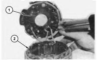
Illustration 1 g03230839
(1) Rectifier
(2) Stator
1. Connect and solder the stator leads to the positive (+) diodes of rectifier (1) .
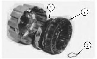
Illustration 2
(1) Rectifier
(2) Stator
(3) Positionwave washer
2. Position the insulators on the rectifier terminal studs. Position rectifier (1), and stator (2) into the rear frame, and install the three screws. Install the terminal insulators, washers, and nuts. Position wave washer (3) into the bearing bore of the rear frame.
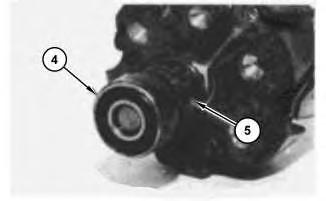
Illustration 3
(4) Rear bearing
(5) Slip ring
g03230842
g03230840
3. Install slip ring (5) on the rotor. Connect and solder the rotor leadsto the slip ring (5). Install rear bearing (4) .
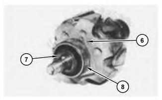
Illustration 4
(6) Bearingcover
(7) Spacer
(8) Front bearing
g03230845
4. Install bearing cover (6), front bearing (8), and spacer (7) on the rotor.
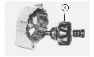
Illustration 5 g03230846
(9) Rotor
5. Install rotor (9) and the four screws into the front frame.
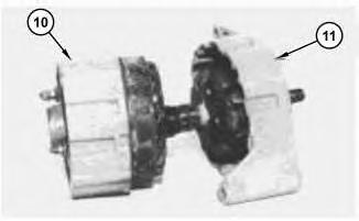
Illustration 6
(10) Stator assembly (11) Rotor assembly
g03230848
6. Assemble front frame and rotor assembly (11) into rear frame and stator assembly (10). Make sure that the wave washer isfixed in the rear frame bearing bore. Align the front and rear frame marks made at disassembly for correct assembly. Install the four screws.
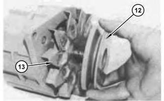
Illustration 7
(12) Pulley (13) Fan
g03230896
7. Install the key, fan (13), pulley (12), washer, and pulley nut. Tighten the nut to a torque of: 3E-7295 Charging Alternator Gp, and 9X-0341 Charging Alternator Gp ... 70 ±5 N·m (52 ± 4 lb ft)
8C-5535 Charging Alternator Gp, 7T-2876 Charging Alternator Gp, 2Y-4212 Charging Alternator Gp, and 2Y-8310 Charging Alternator Gp ... 35 ± 10 N·m (26 ±7 lb ft)
9W-3043 Charging Alternator Gp ... 50 ± 5 N·m (37 ±4 lb ft)
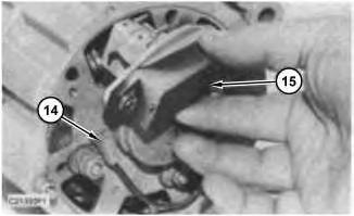
Illustration 8 g03230899 (14) Capacitor lead (15) Regulator
8. Install the capacitor and connect capacitor lead (14) to the back of the alternator.
9. Install regulator (15) .
End By: Install the alternator on the machine. Refer to Disassembly and Assembly, "Alternator - Install"for the machine that is being serviced. Copyright 1993 - 2020 Caterpillar Inc.
Network For SIS Licensees. Sun Sep 27 13:55:16 UTC+0530 2020
Product: EXCAVATOR
Model: 307 EXCAVATOR 2WM
Configuration: 307 Excavator 2WM00500-UP (MACHINE) POWERED BY 3054 Engine
Disassembly and Assembly
Alternator - Bosch K1/N1
i05060896
Alternator - Disassemble
SMCS - 1405-015
Disassembly Procedure
Start By:
A. Remove the alternator. Refer to Disassembly and Assembly, "Alternator - Remove" for the machine that isbeing serviced.
Note: The Disassembly and Assembly that follows is of a K1, 12V7T-2876 Charging Alternator Gp. The other alternators are similar.
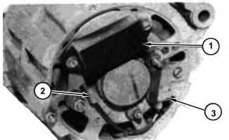
Illustration 1
(2) Capacitor lead
(3) Capacitor
1. Remove the two screws and regulator (1) .
2. Disconnect capacitor lead (2) from the back of the alternator. Remove the screwand capacitor (3) .
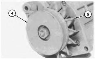
Illustration 2
(4) Pulley (5) Fan
3. Remove the pulley nut, washer, pulley (4), fan (5), and the key from the rotor shaft.

Illustration 3
(6) Screws
g03228056
g03228057
4. Mark the front and rear frame assembliesfor proper assembly. Remove four screws (6) (one hasa nut on it on the back of the alternator).
5. Separate the front frame and rotor assembly from the rear frame and stator assembly. Watch for the wave washer, at the back of the rear frame assembly, to fall out.
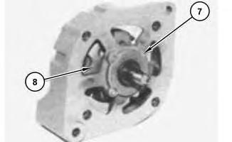
Illustration 4
g03228058 (7) Screws (8) Rotor
6. Remove four screws (7), and rotor (8) from the front frame.

Illustration 5 g03228059 (9) Bearingcover (10) Spacer
This is the sample of the manual click on the download link for complete manual
DOWNLOAD LINK
For some reason if link does not work download this pdf and then click