

Note: Use Bookmarks panel to navigate
Note: Use Bookmarks panel to navigate
For some reason if link does not work download this pdf and then click

Product: MINI HYD EXCAVATOR
Model: 306 MINI HYD EXCAVATOR 6G6
Configuration: 306 CR Mini Hydraulic Excavator 6G600001-UP (MACHINE) POWERED BY C2.4 Engine
Disassembly and Assembly
306 and 306.5 Mini Hydraulic Excavators Machine Systems
Media Number -M0104443-00
Publication Date -01/09/2019
SMCS - 4263-010; 4331-010; 5077-010; 7336-010
Removal Procedure
Date Updated -12/09/2019 i07820481
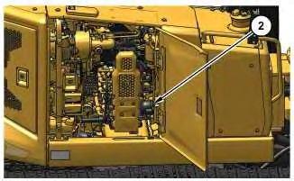
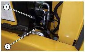
2. Remove accumulator (2).
1. Install accumulator in the reverse order of removal.
a. Tighten accumulator (2) to a torque of 30 ± 5 N·m (22 ± 4 lb ft).
1993 - 2024 Caterpillar Inc.
Rights Reserved.
Network For SIS Licensees. Tue Nov 5 01:29:37 UTC+0530 2024
Product: MINI HYD EXCAVATOR
Model: 306 MINI HYD EXCAVATOR 6G6
Configuration: 306 CR Mini Hydraulic Excavator 6G600001-UP (MACHINE) POWERED BY C2.4 Engine
Disassembly and Assembly
306 and 306.5 Mini Hydraulic Excavators Machine Systems
Media Number -M0104443-00
i07854465
Actuator Motor (Air Temperature Control) - Remove and Install
SMCS - 7304-010-MQ; 7309-010-MQ; 7320-010-MQ
Table 1
Required Tooling Tool Part Number Part
A - Loctite LB8042B 465-7614 Clip 1
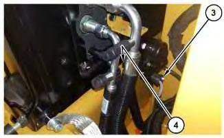
Removal Procedure Illustration 1
1. Remove bolts (1) and bracket (2).
2
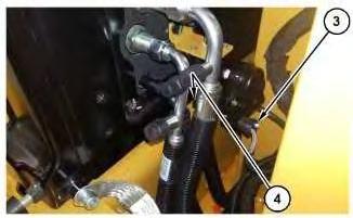
2. Disconnect connector (3) and disconnect hose (4).
3
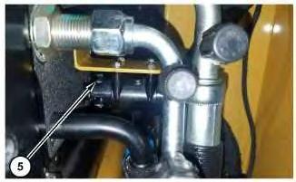
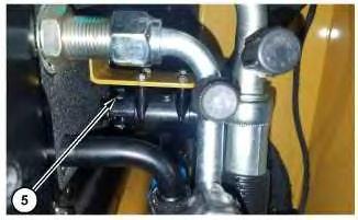
3. Remove clip (5).
4
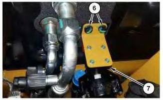
4. Remove bolts (6) and actuator motor (7).
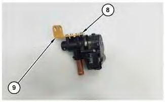
Illustration 5
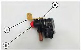
5. Remove four screws (8) and plate (9).
Installation Procedure
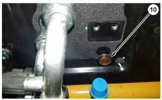
Illustration 6
1. Install O-ring (10) to the fitting.
g06459466
2. Apply Tooling (A) to the outside of O-ring (10).
7
3. Install plate (9) and four screws (8).
4. Install Tooling (B), as shown.

8
5. Install actuator motor (7) and bolts (6). Tighten bolts (6) to a torque of 15 ± 3 N·m (133 ± 27 lb in).
6. Remove Tooling (B).
9
Install clip (5).
10
8. Install hose (4) and connector (3).
11 g06458829
9. Install bracket (2) and bolts (1).
Copyright 1993 - 2024 Caterpillar Inc. All Rights Reserved. Private Network For SIS Licensees. Tue Nov 5 01:16:41 UTC+0530 2024
Product: MINI HYD EXCAVATOR
Model: 306 MINI HYD EXCAVATOR 6G6
Configuration: 306 CR Mini Hydraulic Excavator 6G600001-UP (MACHINE) POWERED BY C2.4 Engine
Disassembly and Assembly
306 and 306.5 Mini Hydraulic Excavators Machine Systems
Media Number -M0104443-00
i07845138
Blade - Remove and Install
SMCS - 6060-010
Removal Procedure Table 1
Required Tools
A 160-2246 Abrasion Sleeve 1
Start By:
a. Remove the blade cylinder.
b. Remove the blade cylinder (angle). Illustration 1
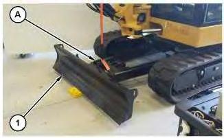
1. Attach Tooling (A) and a suitable lifting device to blade (1). The weight of blade (1) is approximately 327 kg (720 lb).
2
2. Install suitable wedges, as shown.
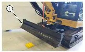
Illustration 3
g06456980
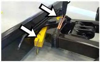
3. Lift blade (1) approximately 41 cm (16 inch).
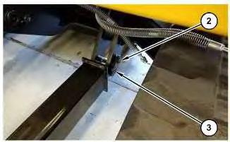
Illustration 4
g06456984
4. Remove bolt (2) and pin (3). Repeat for the opposite side of the machine.

5
5. Remove blade (1).
1. Install blade (1) in the reverse order of removal.
Copyright 1993 - 2024 Caterpillar Inc. All Rights Reserved. Private Network For SIS Licensees.
Tue Nov 5 01:01:24 UTC+0530 2024
Product: MINI HYD EXCAVATOR
Model: 306 MINI HYD EXCAVATOR 6G6
Configuration: 306 CR Mini Hydraulic Excavator 6G600001-UP (MACHINE) POWERED BY C2.4 Engine
Disassembly and Assembly
306 and 306.5 Mini Hydraulic Excavators Machine Systems
SMCS - 7562-010-BG
Removal Procedure Table 1
Required Tooling
NOTICE
Care must be taken to ensure that fluids are contained during performance of inspection, maintenance, testing, adjusting, and repair of the product. Be prepared to collect the fluid with suitable containers before opening any compartment or disassembling any component containing fluids.
Refer to Special Publication, PERJ1017, "Dealer Service Tool Catalog" for tools and supplies suitable to collect and contain fluids on Cat® products.
Dispose of all fluids according to local regulations and mandates.
Hydraulic oil pressure can remain in the hydraulic system after the engine has been stopped. Serious injury can be caused if this pressure is not released before any service is done on the hydraulic system.
Make sure all of the work tools have been lowered to the ground, and the oil is cool before removing any components or lines. Remove the oil filler cap only when the engine is stopped, and the filler cap is cool enough to touch with your bare hand.
1. Release the system pressure. Refer to Operation and Maintenance Manual, "System Pressure - Release" for the correct procedure.
1
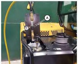
2. Install Tooling (A) onto the hydraulic tank. Attach an air supply hose onto Tooling (A). Apply 138 kPa (20 psi). This procedure will pull a vacuum on the hydraulic system.
2
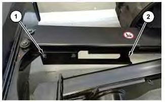
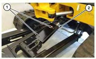
3. Remove four bolts (1) and cover (2).
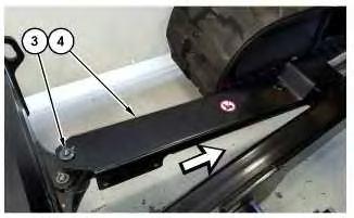
Illustration 3
4. Remove bolt (3) and slide cover (4) towards machine.
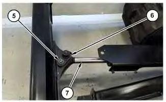
Illustration 4
5. Remove bolt (5) pin (6) and rotate cylinder (7) towards the right track of the machine.
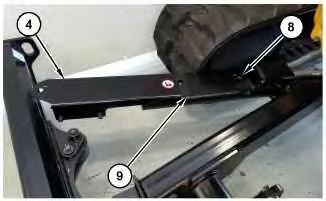
Illustration 5
6. Slide cover (4) forward.
7. Remove bolts (8) and guard assembly (9).
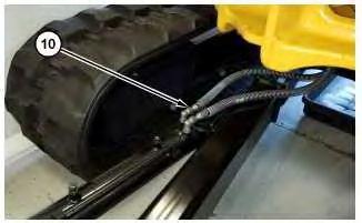
Illustration 6
8. Disconnect two hose assemblies (10).
g06456312
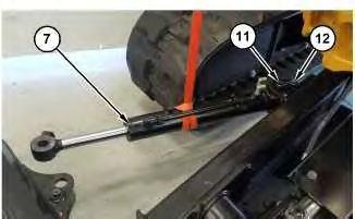
Illustration 7
g06460396
9. Attach a suitable lifting device to blade cylinder (7). The weight of blade cylinder (7) is approximately 27 kg (60 lb).
10. Remove bolt (12) and pin (11).
11. Remove blade cylinder (7).
1. Install blade cylinder (7) in the reverse order of removal.
Copyright 1993 - 2024 Caterpillar Inc. All Rights Reserved. Private Network For SIS Licensees.
Tue Nov 5 01:01:07 UTC+0530 2024
Product: MINI HYD EXCAVATOR
Model: 306 MINI HYD EXCAVATOR 6G6
Configuration: 306 CR Mini Hydraulic Excavator 6G600001-UP (MACHINE) POWERED BY C2.4 Engine
Disassembly and Assembly
306 and 306.5 Mini Hydraulic Excavators Machine Systems
SMCS - 7562-010-BG
Removal Procedure Table 1
Required Tooling
NOTICE
Care must be taken to ensure that fluids are contained during performance of inspection, maintenance, testing, adjusting, and repair of the product. Be prepared to collect the fluid with suitable containers before opening any compartment or disassembling any component containing fluids.
Refer to Special Publication, PERJ1017, "Dealer Service Tool Catalog" for tools and supplies suitable to collect and contain fluids on Cat® products.
Dispose of all fluids according to local regulations and mandates.
i07845067
Hydraulic oil pressure can remain in the hydraulic system after the engine has been stopped. Serious injury can be caused if this pressure is not released before any service is done on the hydraulic system.
Make sure all of the work tools have been lowered to the ground, and the oil is cool before removing any components or lines. Remove the oil filler cap only when the engine is stopped, and the filler cap is cool enough to touch with your bare hand.
1. Release the system pressure. Refer to Operation and Maintenance Manual, "System Pressure - Release" for the correct procedure.
1
2. Install Tooling (A) onto the hydraulic tank. Attach an air supply hose onto Tooling (A). Apply 138 kPa (20 psi). This procedure will pull a vacuum on the hydraulic system.
2
3. Remove bolts (1) and cover (2).
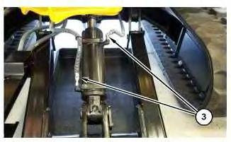
Illustration 3
4. Disconnect hose assemblies (3).
g06455942
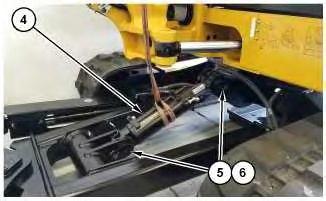
Illustration 4
g06473266
5. Attach a suitable lifting device to blade cylinder (4). The weight of blade cylinder is approximately 36 kg (80 lb).
6. Remove two bolts (5) and two pins (6).
7. Remove blade cylinder (4).
1. Install blade cylinder (4) in the reverse order of removal.
Copyright 1993 - 2024 Caterpillar Inc. All Rights Reserved. Private Network For SIS Licensees.
Tue Nov 5 01:00:49 UTC+0530 2024
Product: MINI HYD EXCAVATOR
Model: 306 MINI HYD EXCAVATOR 6G6
Configuration: 306 CR Mini Hydraulic Excavator 6G600001-UP (MACHINE) POWERED BY C2.4 Engine
Disassembly and Assembly
306 and 306.5 Mini Hydraulic Excavators Machine Systems
SMCS - 7304-010-BW; 7309-010-BW; 7320-010-BW
Removal Procedure
Start By:
a. Remove the seat.
Care must be taken to ensure that fluids are contained during performance of inspection, maintenance, testing, adjusting, and repair of the product. Be prepared to collect the fluid with suitable containers before opening any compartment or disassembling any component containing fluids.
Refer to Special Publication, PERJ1017, "Dealer Service Tool Catalog" for tools and supplies suitable to collect and contain fluids on Cat® products.
Dispose of all fluids according to local regulations and mandates.
Personal injury can result from contact with refrigerant.
Contact with refrigerant can cause frost bite. Keep face and hands away to help prevent injury.
Protective goggles must always be worn when refrigerant lines are opened, even if the gauges indicate the system is empty of refrigerant.
Always use precaution when a fitting is removed. Slowly loosen the fitting. If the system is still under pressure, release it slowly in a well ventilated area.
Personal injury or death can result from inhaling refrigerant through a lit cigarette.
Inhaling air conditioner refrigerant gas through a lit cigarette or other smoking method or inhaling fumes released from a flame contacting air conditioner refrigerant gas, can cause bodily harm or death.
Do not smoke when servicing air conditioners or wherever refrigerant gas may be present.
Use a certified recovery and recycling cart to properly remove the refrigerant from the air conditioning system.
Personal injury can result from hot coolant, steam, and alkali.
At operating temperature, engine coolant is hot and under pressure. The radiator and all lines to heaters or the engine contain hot coolant or steam. Any contact can cause severe burns.
Remove cooling system pressure cap slowly to relieve pressure only when engine is stopped and allow sufficient time for the cooling system to cool.
Do not attempt to tighten hose connections when the coolant is hot, the hose can come off causing burns.
Cooling System Coolant Additive contains alkali. Avoid contact with skin and eyes.
1
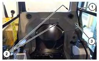
1. Position cover (1) out of the way.
2. Remove two screws (2) and cover (3).
2
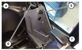
3. Remove three screws (4).
4. Remove nut (5).
5. Disconnect harness assembly (6).
6. Remove cover (7).
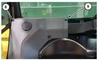
Illustration 3
7. Remove three screws (8) and cover (9).
4
8. Remove screws (10) and duct (11).
5
9. Remove screw (12) and duct (13).
6
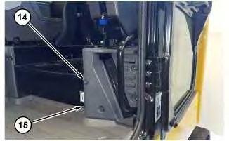
10. Remove bolts (14) and cover (15).
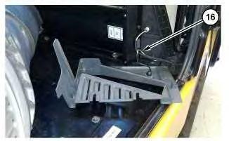
7
11. Disconnect harness assembly (16).
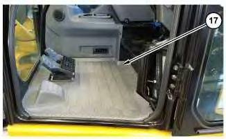
Illustration 8
12. Remove floor mat (17).
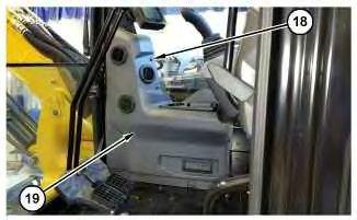
Illustration 9
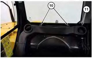
13. Remove eight screws (18) and panel (19).
g06450345
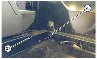
14. Remove screws (20) and cover (21).
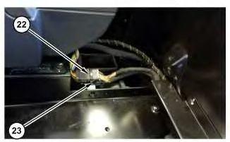
11
15. Cut cable strap (22).
16. Disconnect two harness assemblies (23).
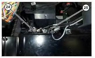
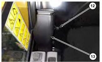
12
17. Position two harness assemblies (24) out of the way.
18. Disconnect harness assemblies (25).
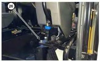
Illustration 13
g06450383
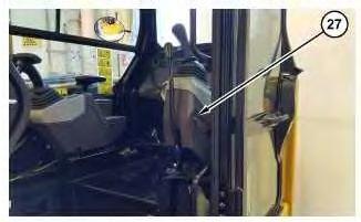
Illustration 14
g06450386
19. Remove four bolts (26) and console assembly (27).
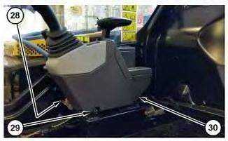
Illustration 15
20. Disconnect two harness assemblies (28).
g06451096
21. Remove four bolts (29) and position console assembly (30) out of the way.
For some reason if link does not work download this pdf and then click