DOWNLOAD LINK
For some reason if link does not work download this pdf and then click
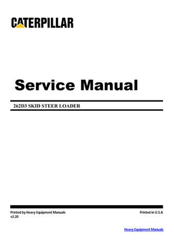
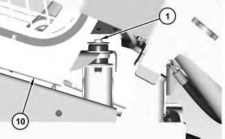
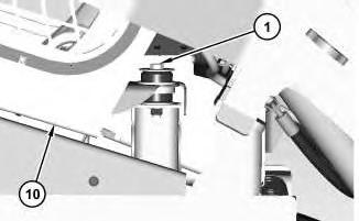
1. Disconnect harness assemblies (1). Disconnect hose assemblies (3), (4), (5), and (7).
2. Remove bolts (6) and accumulator manifold and solenoid mounting (2).
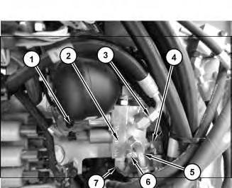
Illustration 2
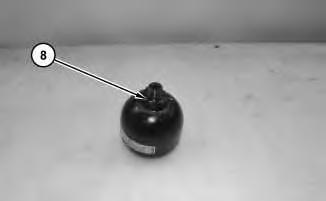
3. Remove accumulator (8).
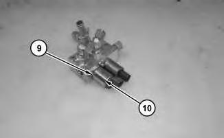
4. Remove bolts (10) and solenoids (9).
g03796775
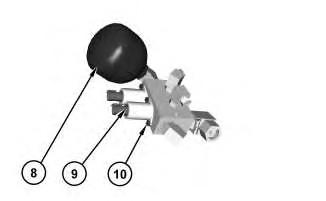
Illustration 3
g03796760
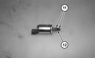
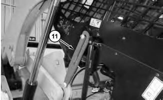
5. Remove O-rings seals (11) from solenoid (9).
Installation Procedure
1. Install accumulator manifold and solenoid mounting (2) in the reverse order of removal.
a. Tighten bolts (10) to a torque of 4 ± 0.5 N·m (35 ± 4 lb in).
b. Tighten accumulator (2) to a torque of 30 ± 4 N·m (266 ± 35 lb in). Copyright 1993 - 2024 Caterpillar Inc.
Thu Feb 15 10:57:41 UTC+0530 2024
Product: SKID STEER LOADER
Model: 262D3 SKID STEER LOADER ZB2
Configuration: 262D3 Skid Steer Loader ZB200001-UP (MACHINE) POWERED BY C3.3B Engine
Disassembly and Assembly
279D3, 289D3, 299D3, and 299D3 XE Compact Track Loaders, and 246D3, 262D3, 272D3, and 272D3 XE Skid Steer Loaders Machine Systems
Accumulator Manifold and Solenoid Mounting (Pilot
Shutoff) - Remove and Install
SMCS - 5077-010; 5264-010; 5479-010
Removal Procedure
Start By:
a. Release the hydraulic system pressure.
b. Tilt the cab.
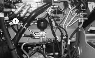
Illustration 1
1. Disconnect hose assemblies (1).
g03736462
i05952543
2
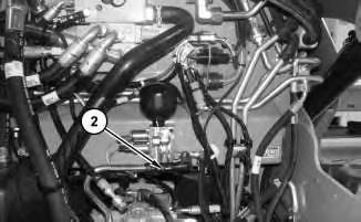
2. Disconnect hose (2).
3
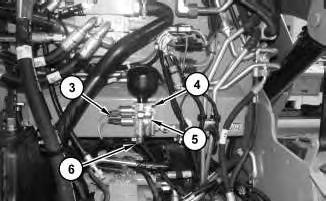
3. Disconnect harness assembly (3) and hose assembly (6). Remove bolts (4) and accumulator manifold and solenoid and mounting (5).
4
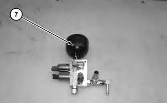
4. Remove accumulator (7).
Illustration
g03736477
Illustration
g03736490
Illustration
g03736521
Illustration 5
5. Remove O-ring seal (8).
g03736532
Illustration 6
6. Remove bolt (9) and solenoid (10).
g03736540
Illustration 7
g03736690
7. Remove O-ring seals (11) and screen (12).
Illustration 8
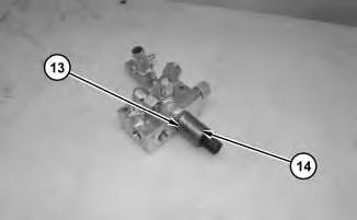
8. Remove bolt (13) and solenoid (14).
g03736693
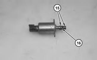
Illustration 9
g03736695
9. Remove O-ring seals (15) and screen (16).
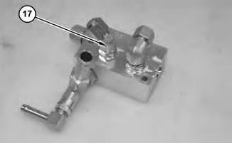
Illustration 10
g03736696
10. Remove four fittings (17) and the O-ring seals.
Installation Procedure
1. Install accumulator manifold and solenoid mounting (5) in the reverse order of removal.
a. Tighten bolt (13) to a torque of 4 ± 0.5 N·m (35 ± 4 lb in).
b. Tighten bolt (9) to a torque of 4 ± 0.5 N·m (35 ± 4 lb in).
c. Tighten accumulator (7) to a torque of 30 ± 4 N·m (22 ± 3 lb ft).
Copyright 1993 - 2024 Caterpillar Inc. All Rights Reserved. Private Network For SIS Licensees. Thu Feb 15 10:57:14 UTC+0530 2024
Product: SKID STEER LOADER
Model: 262D3 SKID STEER LOADER ZB2
Configuration: 262D3 Skid Steer Loader ZB200001-UP (MACHINE) POWERED BY C3.3B Engine
Disassembly and Assembly
279D3, 289D3, 299D3, and 299D3 XE Compact Track Loaders, and 246D3, 262D3, 272D3, and 272D3 XE Skid Steer Loaders Machine Systems
Air Conditioner and Heater - Remove and Install
SMCS - 7309-010
Removal Procedure
i05956640
1. Recover refrigerant. Recover the air conditioner refrigerant from the air conditioner system. Refer to Service Manual, SENR5664, "Air Conditioning and Heating Systems with R-134a Refrigerant" for the procedure. Refer to Special Publication, NENG2500, "Air Conditioning Tools" for the tools.
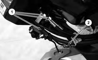
1
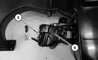
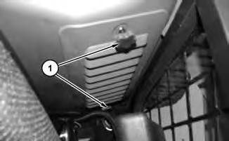
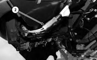
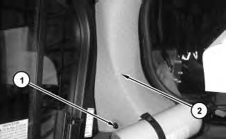
2. Disconnect hose assemblies (1) and harness assembly (2).
Illustration
2
3
4
Illustration
g03738054
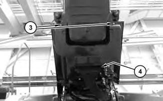
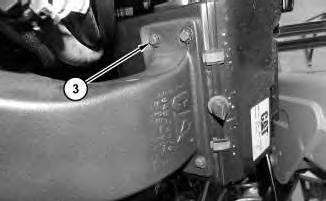
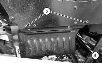
3. Remove bolts (3) and bolts (4).
Illustration
g03738065
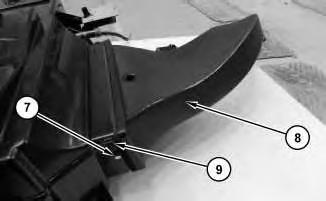
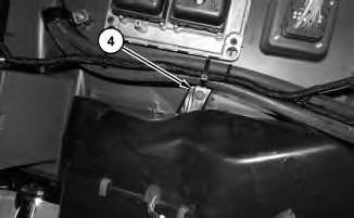
4. Remove bolts (5) and valve (6).
Illustration
g03738077
5. Remove bolts (7), clips (9), and vent (8)
5
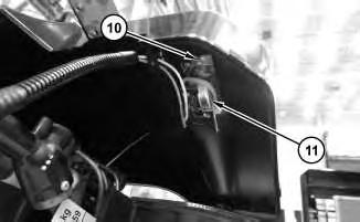
6. Remove bolts (10) and sensor (11).
6
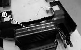
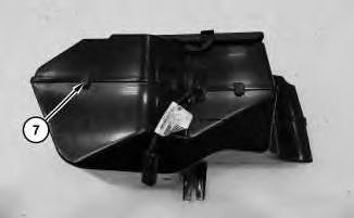
7. Remove air conditioner and heater coil (12).
Installation Procedure
1. Install air conditioner and heater coil (12) in the reverse order of removal.
Copyright 1993 - 2024 Caterpillar Inc. All Rights Reserved. Private Network For SIS Licensees. Thu Feb 15 11:14:55 UTC+0530 2024
Illustration
g03738090
Illustration
g03738093
Product: SKID STEER LOADER
Model: 262D3 SKID STEER LOADER ZB2
Configuration: 262D3 Skid Steer Loader ZB200001-UP (MACHINE) POWERED BY C3.3B Engine
Disassembly and Assembly
279D3, 289D3, 299D3, and 299D3 XE Compact Track Loaders, and 246D3, 262D3, 272D3, and 272D3 XE Skid Steer Loaders Machine Systems
Blower Motor - Remove and Install
i05953017
SMCS - 7301; 7304-010-BW; 7304-010-FM; 7309-010-BW; 7309-010-FM; 7311-010-BW; 7311 -010-FM; 7311-010; 7320-010-FM; 7320-010-BW
Removal Procedure
1
1. Remove filter bolts (1) from the inside of the cab.
2. Tilt the cab.
Illustration
g03736644
Illustration 2
g03736648
3. Disconnect harness (2).
Illustration 3
g03736656
4. Remove bolts (4).
Illustration 4
g03736667
5. Remove bolt (4).
Illustration 5
g03736677
6. Remove bolts (5) and blower assembly (6).
Illustration 6
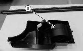
7. Remove clips (7) and separate halves.
g03736682
Illustration 7
8. Remove blower motor (8).
Installation Procedure
g03736683
1. Install blower motor (8) in the reverse order of removal.
Copyright 1993 - 2024 Caterpillar Inc. All Rights Reserved. Private Network For SIS Licensees.
Thu Feb 15 11:15:27 UTC+0530 2024
Product: SKID STEER LOADER
Model: 262D3 SKID STEER LOADER ZB2
Configuration: 262D3 Skid Steer Loader ZB200001-UP (MACHINE) POWERED BY C3.3B Engine
Disassembly and Assembly
279D3, 289D3, 299D3, and 299D3 XE Compact Track Loaders, and 246D3, 262D3, 272D3, and 272D3 XE Skid Steer Loaders Machine Systems
Cab - Remove and Install - Extended Reach
SMCS - 7301-010; 7325-010
S/N - AN91-UP
S/N - BT21-UP
S/N - BT91-UP
S/N - BX91-UP
S/N - CY91-UP
S/N - DY91-UP
S/N - EP81-UP
S/N - EP91-UP
S/N - GJ21-UP
S/N - HX21-UP
S/N - JX91-UP
S/N - KX91-UP
S/N - LA91-UP
S/N - LB31-UP
S/N - MXJ1-UP
S/N - W6E1-UP
i07500623
S/N - XES1-UP
S/N - ZB21-UP
Removal Procedure
Table 1
Required Tools
Tool Part Number Part Description Qty
A 140-7742 Sleeve 4
B 207-1601 Rubber Lubricant -
C - Loctite 243 -
Note: The gas spring on the right side of the machine must be removed before removing the gas spring on the left side of the machine.
Personal injury can result from contact with refrigerant.
Contact with refrigerant can cause frost bite. Keep face and hands away to help prevent injury.
Protective goggles must always be worn when refrigerant lines are opened, even if the gauges indicate the system is empty of refrigerant.
Always use precaution when a fitting is removed. Slowly loosen the fitting. If the system is still under pressure, release it slowly in a well ventilated area.
Personal injury or death can result from inhaling refrigerant through a lit cigarette.
Inhaling air conditioner refrigerant gas through a lit cigarette or other smoking method or inhaling fumes released from a flame contacting air conditioner refrigerant gas, can cause bodily harm or death.
Do not smoke when servicing air conditioners or wherever refrigerant gas may be present.
Use a certified recovery and recycling cart to properly remove the refrigerant from the air conditioning system.
1. Recover the refrigerant. Refer to Service Manual, SENR5664, "All Products Air Conditioning and Heating Systems with R-134a for All Caterpillar Machines" for the recovery and the charging procedure. Refer to Special Publication, NENG2500, "Air Conditioning Tools" for the correct tools.
2. Drain the coolant. Refer to Operation and Maintenance Manual, "Cooling System Coolant (ELC) - Change" for the correct draining and filling procedure.
Illustration 1
g03738355
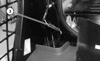
3. Remove clip (1) and cover (2).
Illustration 2
g03738445
4. Disconnect harness assembly (3).
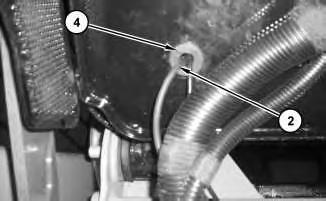
5. Tilt the cab.
3
6. Remove grommet (4) and harness assembly (2).
Illustration 4
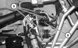
7. Disconnect harness assemblies (5) and cable assembly (6).
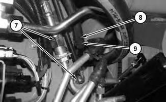
Illustration 5
8. Disconnect hose assemblies (7), hose (8), and hose (9).
Illustration
g03738452
g03736732
g03736733
6
9. Disconnect ground strap (10). Remove clip (11).
7
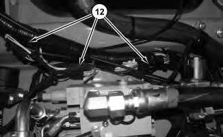
10. Disconnect harness assemblies (12).
8
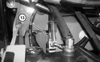
11. Disconnect cable assembly (13).
Illustration
g03738500
Illustration
g03736734
Illustration
g03736736
9
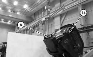
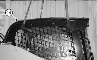
12. Attach Tooling (A) and a suitable lifting device to cab (14). The weight of cab (14) is approximately 290 kg (640 lb). Use Tooling (A) and the suitable lifting device to raise cab (14) enough to fully extend gas spring (17).
Illustration 10
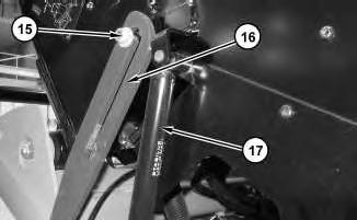
13. Remove gas spring (17). Refer to Disassembly and Assembly, "Gas Spring - Remove and Install". Repeat for opposite side.
14. Remove cab support lever (16).
11
Illustration
g03738508
g03736738
Illustration
g03736740
15. Attach a suitable lifting device to cab (14). The weight of cab (15) is approximately 290 kg (640 lb). Remove bolts (18) and cab (15).
Installation Procedure
1. Install cab (14) in the reverse order of removal.
2. Apply Tooling (C) to bolt (15).
3. Apply Tooling (B) to the rubber mounts. Tighten mount bolts (18) to a torque of 55 ± 5 N·m (41 ± 4 lb ft).
Product: SKID STEER LOADER
Model: 262D3 SKID STEER LOADER ZB2
Configuration: 262D3 Skid Steer Loader ZB200001-UP (MACHINE) POWERED BY C3.3B Engine
Disassembly and Assembly
279D3, 289D3, 299D3, and 299D3 XE Compact Track Loaders, and 246D3, 262D3, 272D3, and 272D3 XE Skid Steer Loaders Machine Systems
Cab - Tilt
SMCS - 7301-084
Raising the Cab
Do not go beneath cab unless cab is empty and support lever is engaged.
Failure to follow the instructions or heed the warnings could result in injury or death.
Do not tilt the cab using an open door. The door must be closed and latched when lifting the cab. The door may become dislodged from its hinges and may cause serious personal injury or death.
1. Park the machine on level ground.
2. Remove the interior cab air filter.
3. If you tilt the cab upward with the loader lift arms in the RAISED position, engage the brace for the loader lift arms. Refer to Operation and Maintenance Manual, "Loader Lift Arm Brace Operation" for the process for engaging the brace for the loader lift arms.
4. Close the cab door and ensure that the door is latched.
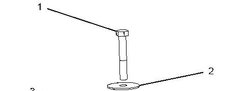
Illustration 1
g02896278
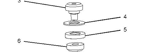
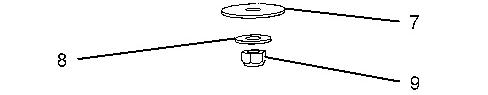
Illustration 2 g02896156
5. Remove bolt (1). Remove washer (2), rubber mount (3), washer (4), spacer (5), rubber mount (6), washer (7), washer (8), and nut (9).
Note: Note the location of the rubber mounts and the spacers for assembly purposes.
6. Raise cab (10).
3
7. Raise the cab until the cab support lever (11) is in the ENGAGED position.
Lowering the Cab
Illustration 4
1. Raise the cab. With the help of another person, release the cab support lever (11).
5
Illustration
g02896356
g02896356
Illustration
g02896278
Illustration 6 g02896156
2. Lower cab (10).
3. Install nut (9), washer (8), washer (7), rubber mount (6), spacer (5), washer (4), rubber mount (3), and washer (2). Install bolt (1). Tighten bolts (1) to a torque of 125 ± 10 N·m (92 ± 7 lb ft).
Copyright 1993 - 2024 Caterpillar Inc. All Rights Reserved. Private Network For SIS Licensees. Thu Feb 15 11:10:32 UTC+0530 2024
This is the sample of the manual click on the download link for complete manual