

246D3 SKID STEER LOADER


Product: SKID STEER LOADER
Model: 246D3 SKID STEER LOADER KC6
Configuration: 246D3 Skid Steer Loader KC600001-UP (MACHINE) POWERED BY C3.3B Engine
Disassembly and Assembly
279D3, 289D3, 299D3, and 299D3 XE Compact Track Loaders, and 246D3, 262D3, 272D3, and 272D3 XE Skid Steer Loaders Machine Systems
Accumulator Manifold and Solenoid Mounting (Pilot Shutoff) - Remove and Install
SMCS - 5077-010; 5264-010; 5479-010
Removal Procedure
Start By:
a. Release the hydraulic system pressure.
b. Tilt the cab.
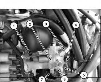
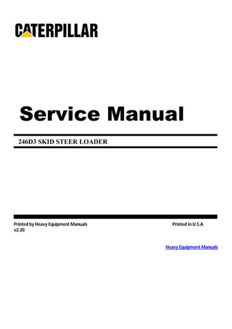
Illustration 1
For some reason if link deos not work download this pdf and then click
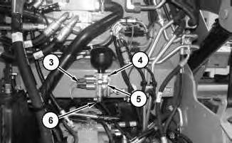
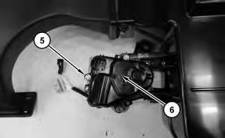
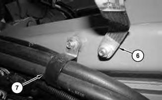
1. Disconnect harness assemblies (1). Disconnect hose assemblies (3), (4), (5), and (7).
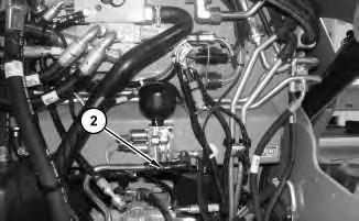
2. Remove bolts (6) and accumulator manifold and solenoid mounting (2).
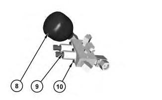
Illustration 2
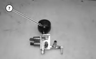
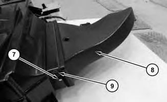
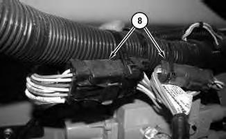
3. Remove accumulator (8).
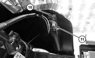
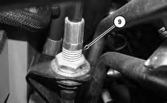
4. Remove bolts (10) and solenoids (9).
g03796775
Illustration 3
g03796760
5. Remove O-rings seals (11) from solenoid (9).
Installation Procedure
1. Install accumulator manifold and solenoid mounting (2) in the reverse order of removal.
a. Tighten bolts (10) to a torque of 4 ± 0.5 N·m (35 ± 4 lb in).
b. Tighten accumulator (2) to a torque of 30 ± 4 N·m (266 ± 35 lb in). Copyright 1993 - 2024 Caterpillar Inc.
Thu Dec 12 09:45:01 UTC+0530 2024
Product: SKID STEER LOADER
Model: 246D3 SKID STEER LOADER KC6
Configuration: 246D3 Skid Steer Loader KC600001-UP (MACHINE) POWERED BY C3.3B Engine
Disassembly and Assembly
279D3, 289D3, 299D3, and 299D3 XE Compact Track Loaders, and 246D3, 262D3, 272D3, and 272D3 XE Skid Steer Loaders Machine Systems
Accumulator Manifold and Solenoid Mounting (Pilot Shutoff) - Remove and Install
SMCS - 5077-010; 5264-010; 5479-010
Removal Procedure
Start By:
a. Release the hydraulic system pressure.
b. Tilt the cab.
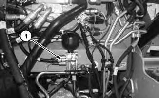
Illustration 1
1. Disconnect hose assemblies (1).
g03736462
i05952543
2
2. Disconnect hose (2).
3
3. Disconnect harness assembly (3) and hose assembly (6). Remove bolts (4) and accumulator manifold and solenoid and mounting (5).
4
4. Remove accumulator (7).
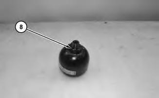
Illustration 5
5. Remove O-ring seal (8).
g03736532
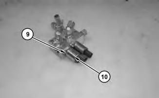
Illustration 6
6. Remove bolt (9) and solenoid (10).
g03736540
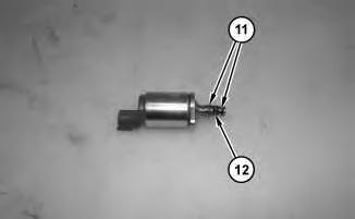
Illustration 7
g03736690
7. Remove O-ring seals (11) and screen (12).
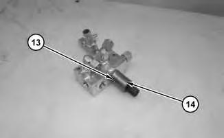
Illustration 8
8. Remove bolt (13) and solenoid (14).
g03736693
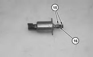
Illustration 9
g03736695
9. Remove O-ring seals (15) and screen (16).
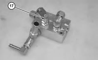
Illustration 10
g03736696
10. Remove four fittings (17) and the O-ring seals.
Installation Procedure
1. Install accumulator manifold and solenoid mounting (5) in the reverse order of removal.
a. Tighten bolt (13) to a torque of 4 ± 0.5 N·m (35 ± 4 lb in).
b. Tighten bolt (9) to a torque of 4 ± 0.5 N·m (35 ± 4 lb in).
c. Tighten accumulator (7) to a torque of 30 ± 4 N·m (22 ± 3 lb ft).
Copyright 1993 - 2024 Caterpillar Inc. All Rights Reserved. Private Network For SIS Licensees. Thu Dec 12 09:44:42 UTC+0530 2024
Product: SKID STEER LOADER
Model: 246D3 SKID STEER LOADER KC6
Configuration: 246D3 Skid Steer Loader KC600001-UP (MACHINE) POWERED BY C3.3B Engine
Disassembly and Assembly
279D3, 289D3, 299D3, and 299D3 XE Compact Track Loaders, and 246D3, 262D3, 272D3, and 272D3 XE Skid Steer Loaders Machine Systems
Air Conditioner and Heater - Remove and Install
SMCS - 7309-010
Removal Procedure
i05956640
1. Recover refrigerant. Recover the air conditioner refrigerant from the air conditioner system. Refer to Service Manual, SENR5664, "Air Conditioning and Heating Systems with R-134a Refrigerant" for the procedure. Refer to Special Publication, NENG2500, "Air Conditioning Tools" for the tools.
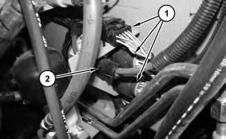
1
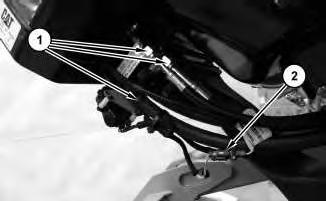
2. Disconnect hose assemblies (1) and harness assembly (2).
2
3
4
5
6. Remove bolts (10) and sensor (11).

6
7. Remove air conditioner and heater coil (12).
Installation Procedure
1. Install air conditioner and heater coil (12) in the reverse order of removal.
Copyright 1993 - 2024 Caterpillar Inc. All Rights Reserved. Private Network For SIS Licensees. Thu Dec 12 09:52:24 UTC+0530 2024
Product: SKID STEER LOADER
Model: 246D3 SKID STEER LOADER KC6
Configuration: 246D3 Skid Steer Loader KC600001-UP (MACHINE) POWERED BY C3.3B Engine
Disassembly and Assembly
279D3, 289D3, 299D3, and 299D3 XE Compact Track Loaders, and 246D3, 262D3, 272D3, and 272D3 XE Skid Steer Loaders Machine Systems
Blower Motor - Remove and Install
i05953017
SMCS - 7301; 7304-010-BW; 7304-010-FM; 7309-010-BW; 7309-010-FM; 7311-010-BW; 7311 -010-FM; 7311-010; 7320-010-BW; 7320-010-FM
Removal Procedure
1
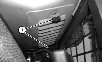
1. Remove filter bolts (1) from the inside of the cab.
2. Tilt the cab.
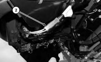
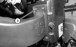
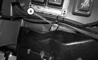
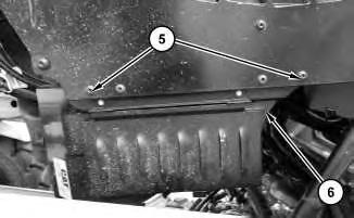
Illustration 5
g03736677
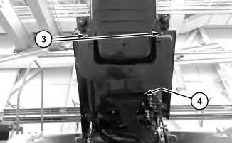
6. Remove bolts (5) and blower assembly (6).
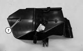
Illustration 6
7. Remove clips (7) and separate halves.
g03736682
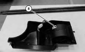
Illustration 7
8. Remove blower motor (8).
Installation Procedure
g03736683
1. Install blower motor (8) in the reverse order of removal.
Copyright 1993 - 2024 Caterpillar Inc. All Rights Reserved. Private Network For SIS Licensees.
Thu Dec 12 09:52:41 UTC+0530 2024
Product: SKID STEER LOADER
Model: 246D3 SKID STEER LOADER KC6
Configuration: 246D3 Skid Steer Loader KC600001-UP (MACHINE) POWERED BY C3.3B Engine
Disassembly and Assembly
279D3, 289D3, 299D3, and 299D3 XE Compact Track Loaders, and 246D3, 262D3, 272D3, and 272D3 XE Skid Steer Loaders Machine Systems
Cab - Remove and Install - Radial Lift
SMCS - 7301-010; 7325-010
S/N - AH61-UP
S/N - EP31-UP
S/N - EP71-UP
S/N - GM61-UP
S/N - KC61-UP
S/N - PF61-UP
S/N - RB91-UP
S/N - SZ91-UP
S/N - TB91-UP
S/N - Z9E1-UP
Removal Procedure
Start By:
a. Tilt the cab.
i05349669
1. Refer to Service Manual, SENR5664, "Air Conditioning and Heating Systems with R-134a Refrigerant" for the procedure. Refer to Dealer Service Tool Catalog, NENG2500, "Air Conditioning Tools" for the correct tools.
2. Refer to Operation and Maintenance Manual, "Cooling System Coolant (ELC) - Change" for the correct draining and filling procedure.
1
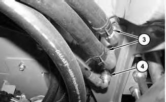
Illustration 2
4. Disconnect hoses (3) and hose assembly (4).
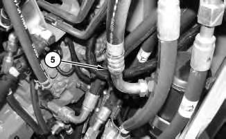
Illustration 3
5. Disconnect hose assembly (5).
4
6. Disconnect ground strap (6). Remove clip (7).
5
7. Disconnect harness assemblies (8).
6
8. Disconnect cable assembly (9).
7
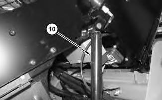
Illustration 8
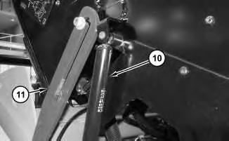
9. Remove gas springs (10). Refer to Disassembly and Assembly, "Gas Spring - Remove and Install".
10. Remove cab support lever (11).
9
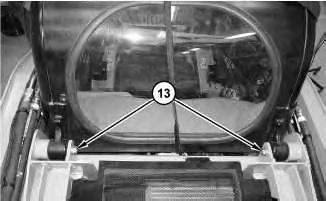
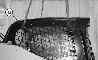
11. Use the suitable lifting device to lower cab assembly (12). Remove bolts (13).
12. Use the suitable lifting device to remove cab assembly (12). The weight of cab assembly (12) is approximately 290 kg (640 lb).
Installation Procedure
1. Install cab assembly (12) in the reverse order of removal.
Copyright 1993 - 2024 Caterpillar Inc. All Rights Reserved. Private Network For SIS Licensees. Thu Dec 12 09:50:40 UTC+0530 2024
Product: SKID STEER LOADER
Model: 246D3 SKID STEER LOADER KC6
Configuration: 246D3 Skid Steer Loader KC600001-UP (MACHINE) POWERED BY C3.3B Engine
Disassembly and Assembly
279D3, 289D3, 299D3, and 299D3 XE Compact Track Loaders, and 246D3, 262D3, 272D3, and 272D3 XE Skid Steer Loaders Machine Systems
Cab - Tilt
SMCS - 7301-084
Raising the Cab
Do not go beneath cab unless cab is empty and support lever is engaged.
Failure to follow the instructions or heed the warnings could result in injury or death.
Do not tilt the cab using an open door. The door must be closed and latched when lifting the cab. The door may become dislodged from its hinges and may cause serious personal injury or death.
1. Park the machine on level ground.
2. Remove the interior cab air filter.
3. If you tilt the cab upward with the loader lift arms in the RAISED position, engage the brace for the loader lift arms. Refer to Operation and Maintenance Manual, "Loader Lift Arm Brace Operation" for the process for engaging the brace for the loader lift arms.
4. Close the cab door and ensure that the door is latched.
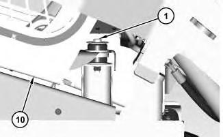
Illustration 1
g02896278
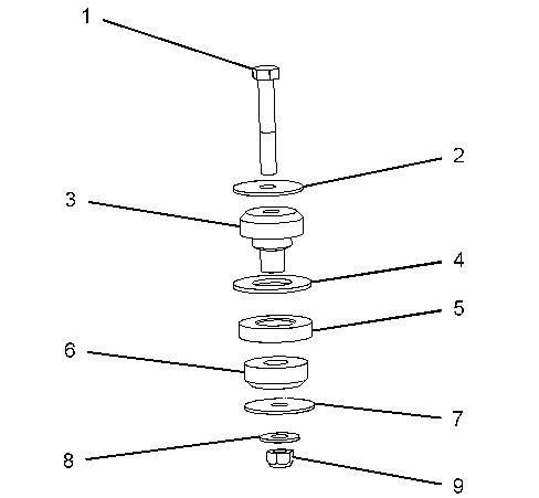
Illustration 2 g02896156
5. Remove bolt (1). Remove washer (2), rubber mount (3), washer (4), spacer (5), rubber mount (6), washer (7), washer (8), and nut (9).
Note: Note the location of the rubber mounts and the spacers for assembly purposes.
6. Raise cab (10).
3
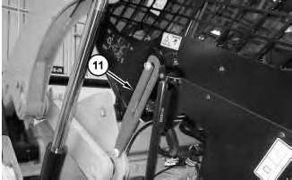
7. Raise the cab until the cab support lever (11) is in the ENGAGED position.
Lowering the Cab
Illustration 4
1. Raise the cab. With the help of another person, release the cab support lever (11).
5
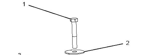
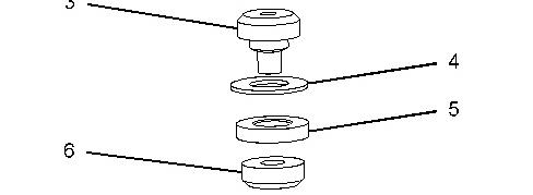
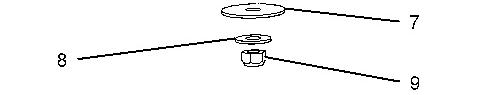
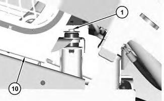
Illustration 6 g02896156
2. Lower cab (10).
3. Install nut (9), washer (8), washer (7), rubber mount (6), spacer (5), washer (4), rubber mount (3), and washer (2). Install bolt (1). Tighten bolts (1) to a torque of 125 ± 10 N·m (92 ± 7 lb ft).
Copyright 1993 - 2024 Caterpillar Inc. All Rights Reserved. Private Network For SIS Licensees. Thu Dec 12 09:50:23 UTC+0530 2024
Product: SKID STEER LOADER
Model: 246D3 SKID STEER LOADER KC6
Configuration: 246D3 Skid Steer Loader KC600001-UP (MACHINE) POWERED BY C3.3B Engine
Disassembly and Assembly
279D3, 289D3, 299D3, and 299D3 XE Compact Track Loaders, and 246D3, 262D3, 272D3, and 272D3 XE Skid Steer Loaders Machine Systems
i04824912
Control Valve (Work Tool) - Assemble - High Flow
SMCS - 5051-016
Assembly Procedure
Table 1
Required Tools
Tool Part Number Part Description Qty
A 341-4073 Spanner Wrench 1
B 367-9109 Digital Caliper 1
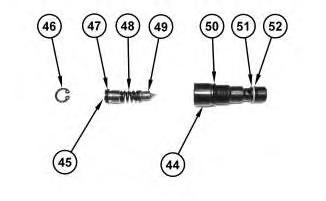
Illustration 1
g02954485
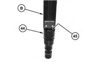
Illustration 2
Improper assembly of parts that are spring loaded can cause bodily injury.
To prevent possible injury, follow the established assembly procedure and wear protective equipment.
1. Install O-ring seal (52), back-up ring (51), and O-ring seal (50) onto valve assembly (44).
2. Install valve (49) and spring (48).
3. Install O-ring seal (47) onto plug (45), and install plug (45) and retaining ring (46).
Note: Refer to the measurement recorded during the Disassembly Process. Use Tooling (B) to determine correct depth of plug (45).
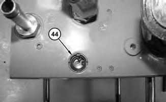
Illustration 3
g02954457
4. Install valve assembly (44). Use Tooling (A) in order to tighten valve assembly (44) to a torque of 12.5 ± 2.5 N·m (110.63 ± 22.13 lb in).
For some reason if link deos not work download this pdf and then click