
SKID STEER LOADER


Previous Screen
Product: SKID STEER LOADER
Model: 242 SKID STEER LOADER CMB
Shutdown SIS
Configuration: 216 226 232 242 Skid Steer Loader CMB00001-UP (MACHINE) POWERED BY 3024C, 3034 Engine
Disassembly and Assembly
226 and 242 Skid Steer Loaders Power Train
Axle - Assemble
SMCS - 3278-016
S/N - 5FZ6700-UP
S/N - CMB1-UP
Assembly Procedure Table 1 Required
C 159-3285 Bearing Installation Tool 1
D 1P-0808 Multipurpose Grease 1
Note: Cleanliness is an important factor. Before assembly, thoroughly clean all parts in cleaning fluid. Allow the parts to air dry. Do not use wiping cloths or rags to dry parts. Lint may be deposited on the parts which may cause trouble. Inspect all parts. If any parts are worn or damaged, use new parts for replacement. Dirt and other contaminants can damage the precision component. Perform assembly procedures on a clean work surface. Keep components covered and protected at all times.
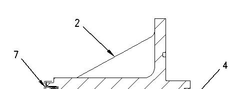
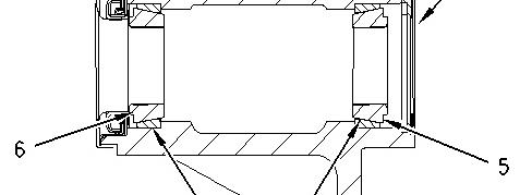

Illustration 1 g00682639
(2) Axle Housing
(4) Lip Type Seal
(5) Roller Bearing
(6) Roller Bearing
(7) Lip Type Seal
(8) Bearing Cup
(9) Bearing Cup
1. Illustration 1 shows the location of the components that are in the axle assembly.
Illustration 2
Typical Example
2. Use a suitable press and Tooling (A) to install bearing cup (9) .
Note: Ensure that the bearing cup is seated.
3. Repeat Step 2 for bearing cup (8) on the other side.
4. Refill the cavity of the housing to one-third capacity with Tooling (D) .
3
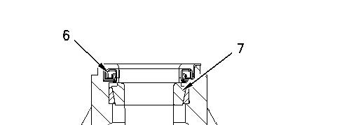
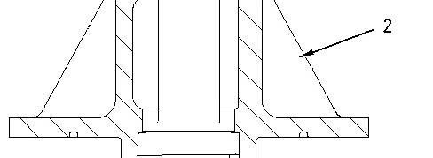

Illustration 4 g00581317
Note: Apply clean hydraulic oil on the sealing lip of a new lip type seal.
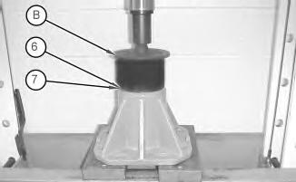
5. Pack bearing (7) with Tooling (D) . Use a suitable press and Tooling (B) to install bearing (7) . Use a suitable press and Tooling (B) to install seal (6) .
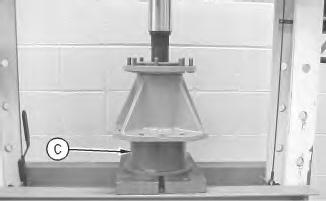
Illustration 5 g00788455
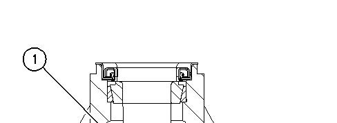
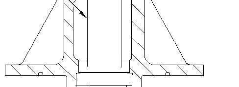

Illustration 6 g00692732
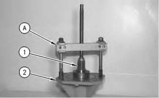
6. Position shaft (1) into the housing. Use a suitable press and Tooling (C) to seat shaft (1) .
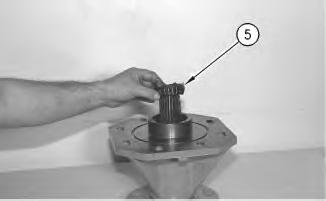
Illustration 7 g00683066
7. Pack bearing (5) with Tooling (D) . Install bearing (5) .
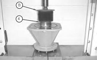
Illustration 8
g01412085
Note: Apply clean hydraulic oil on the sealing lip of a new lip type seal.
8. Use a suitable press and Tooling (B) to install seal (4) .
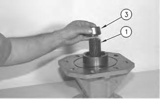
Illustration 9
9. Position spacer (3) over shaft (1) .
g00913233
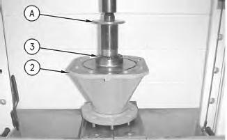
10
10. Use a suitable press and Tooling (A) to install spacer (3) in housing (2) .
End By: Install the axle. Refer to Disassembly and Assembly, "Axle - Install".
Copyright 1993 - 2020 Caterpillar Inc. All Rights Reserved. Private Network For SIS Licensees. Sat Apr 25 09:43:17 UTC+0530 2020
Previous Screen
Product: SKID STEER LOADER
Model: 242 SKID STEER LOADER CMB
Shutdown SIS
Configuration: 216 226 232 242 Skid Steer Loader CMB00001-UP (MACHINE) POWERED BY 3024C, 3034 Engine
Disassembly and Assembly
226 and 242 Skid Steer Loaders Power Train
i01784546
Axle - Disassemble
SMCS - 3278-015
S/N - 5FZ6700-UP
S/N - CMB1-UP
Disassembly Procedure
Table 1 Required Tools
126-7181 Puller Plate 4
6V-4832 Screw 1
8H-0663 Bearing Puller 1
Start By:
A. Remove the axle. Refer to Disassembly and Assembly, "Axle - Remove ".
NOTICE
Care must be taken to ensure that fluids are contained during performance of inspection, maintenance, testing, adjusting and repair of the product. Be prepared to collect the fluid with suitable containers before opening any compartment or disassembling any component containing fluids.
Refer to Special Publication, NENG2500, "Caterpillar Tools and Shop Products Guide" for tools and supplies suitable to collect and contain fluids on Caterpillar products.
Dispose of all fluids according to local regulations and mandates.
Note: Cleanliness is an important factor. Before you begin the disassembly procedure, the exterior of the components should be thoroughly cleaned. This will help to prevent dirt from entering the internal mechanism. Precision components can be damaged by contaminants or by dirt. Perform disassembly procedures on a clean work surface. Keep components covered and protected at all times.
1. Use Tooling (A) to release shaft (1) from axle housing (2) .
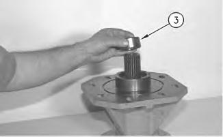
Illustration 2
2. Remove spacer (3). Remove the shaft from the housing.
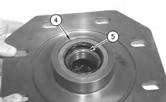
Illustration 3
3. Remove seal (4) .
4. Remove bearing (5) .
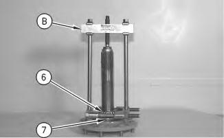
Illustration 4
5. Use Tooling (B) to remove bearing (6) .
6. Remove seal (7) .
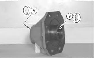
Illustration 5
g00682622
7. Remove bearing cup (8). Remove bearing cup (9) .
Illustration 6 g00682639
(2) Axle Housing
(4) Lip Type Seal
(5) Roller Bearing
(6) Roller Bearing
(7) Lip Type Seal
(8) Bearing Cup
(9) Bearing Cup
8. Illustration 6 shows the location of the components that are in the axle assembly.
Copyright 1993 - 2020 Caterpillar Inc. All Rights Reserved. Private Network For SIS Licensees. Sat Apr 25 09:43:01 UTC+0530 2020
Previous Screen
Product: SKID STEER LOADER
Model: 242 SKID STEER LOADER CMB
Configuration: 216 226 232 242 Skid Steer Loader CMB00001-UP (MACHINE) POWERED BY 3024C, 3034 Engine
Disassembly and Assembly
226 and 242 Skid Steer Loaders Power Train
Axle -
Install
SMCS - 3278-012
S/N - 5FZ6700-UP
S/N - CMB1-UP
Installation Procedure
1
Note: Cleanliness is an important factor. Before assembly, thoroughly clean all parts in cleaning fluid. Allow the parts to air dry. Do not use wiping cloths or rags to dry parts. Lint may be deposited on the parts which may cause trouble. Inspect all parts. If any parts are worn or damaged, use new parts for replacement. Dirt and other contaminants can damage the precision component. Perform assembly procedures on a clean work surface. Keep components covered and protected at all times.
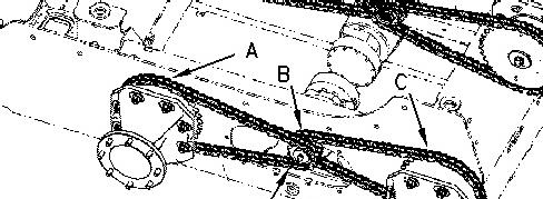
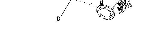
Illustration 1 g00577375
1. The front axle assemblies and the rear axle assemblies are driven by different drive chains. The drive chains are installed on Drive Sprocket (B) and Drive Sprocket (D). The drive sprockets are mounted on the drive shaft of the hydrostatic piston motor. The two drive sprockets are the same component. The drive sprocket on the hydrostatic piston motor has sprocket drives on different planes. The drive sprockets on the front and rear axles are the same component. The sprockets on the front and rear axles are mounted at 180 degrees of opposite direction. Note that Sprocket (A) is in line with Drive Sprocket (D) and that Sprocket (C) is in line with Drive Sprocket (B). The drive sprockets are installed in a manner that will allow the drive chains to turn in a straight line. If any of the sprockets are installed incorrectly the drive chains can not be installed properly. Note the orientation of all of Drive Sprocket (B) and Drive Sprocket (D). Note the orientation of Sprocket (A) and Sprocket (C) on the axles. Mark all components prior to any removal for repair or replacement.
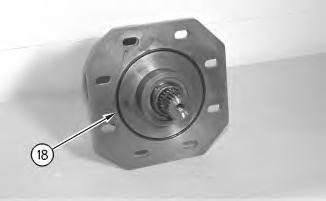
Illustration 2
2. Install O-ring seal (18) .
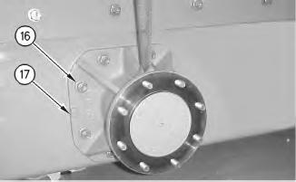
Illustration 3 g00912874
3. Install axle assembly (17). The weight of the axle assembly is approximately 37 kg (82 lb).
4. Install nuts (16) hand tight.
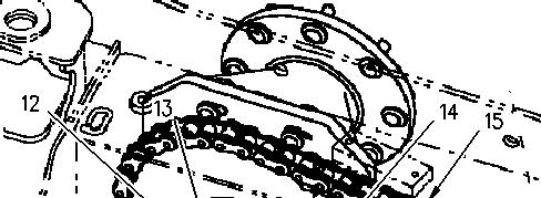
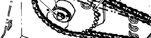
Illustration 4 g00913026
5
Note: Be sure that the drive sprockets are facing the proper direction in order for the drive chains to turn in a straight line.
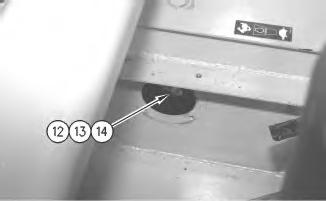
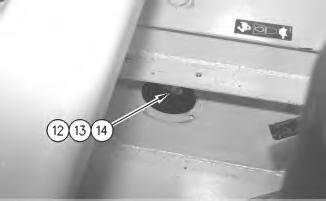
5. Install chain assembly (15). Install sprocket (14) .
6. Install washer (13). Install bolt (12) .
6
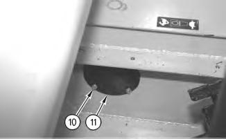
7. Use Tooling (B) to apply a continuous bead around the access holes in the machine frame. Install plate (11). Install bolts (10) .

Illustration 7
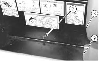
8. Install plate (9). Install plate (8). Install screws (7) .
9. Adjust the drive chain tension. Refer to Disassembly and Assembly, "Chain (Drive) - Adjust".
10. Refill the drive chain oil. Refer to Operation and Maintenance Manual, SEBU7468, "Drive Chain Case Oil - Change".
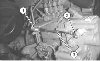
Illustration 8
11. Position governor cable (3) .
12. Install nut (2) .
13. Tighten the nut (1) .
14. Repeat Steps 2 through 13 for the other axles. , End By:
a. Install the tire and rim. Refer to Disassembly and Assembly, "Tire and Rim - Remove and Install".
b. Lower the cab. Refer to Disassembly and AssemblyRENR4838, "Cab - Tilt".
Copyright 1993 - 2020 Caterpillar Inc. All Rights Reserved. Private Network For SIS Licensees. Sat Apr 25 09:43:34 UTC+0530 2020
Previous Screen
Product: SKID STEER LOADER
Model: 242 SKID STEER LOADER CMB
Shutdown SIS
Configuration: 216 226 232 242 Skid Steer Loader CMB00001-UP (MACHINE) POWERED BY 3024C, 3034 Engine
Disassembly and Assembly
226 and 242 Skid Steer Loaders Power Train
i01784534
Axle - Remove
SMCS - 3278-011
S/N - 5FZ6700-UP
S/N - CMB1-UP
Removal Procedure
Table 1
A 169-5464 Quick Cure Primer 1
B 5P-3413 Pipe Sealant 1
Start By:
A. Remove the tire and rim. Refer to Disassembly and Assembly, "Tire and Rim - Remove and Install".
B. Tilt the cab. Refer to Disassembly and Assembly, RENR4838, "Cab - Tilt".
NOTICE
Care must be taken to ensure that fluids are contained during performance of inspection, maintenance, testing, adjusting and repair of the product. Be prepared to collect the fluid with suitable containers
before opening any compartment or disassembling any component containing fluids.
Refer to Special Publication, NENG2500, "Caterpillar Tools and Shop Products Guide" for tools and supplies suitable to collect and contain fluids on Caterpillar products.
Dispose of all fluids according to local regulations and mandates.
Note: Put identification marks on all hoses, on all hose assemblies, on all wires, and on all tube assemblies for installation purposes. Plug all hose assemblies and all tube assemblies. This helps to prevent fluid loss, and this helps to keep contaminants from entering the system.
Note: Cleanliness is an important factor. Before you begin the disassembly procedure, the exterior of the components should be thoroughly cleaned. This will help to prevent dirt from entering the internal mechanism. Precision components can be damaged by contaminants or by dirt. Perform disassembly procedures on a clean work surface. Keep components covered and protected at all times.
2
4. Remove plug (4). Drain the drive chain oil into a suitable container. Apply Tooling (A) to plug (4). Apply Tooling (B) to plug (4). Install plug (4) .
5. Remove bolts (5) .
6. Remove cover (6) .
3
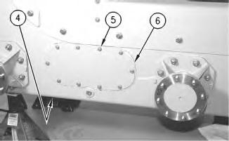
7. Remove screws (7). Remove plate (8). Move plate (9) aside.

4
8. Remove bolts (10). Remove plate (11) .
5
Illustration 6 g00913026
9. Remove bolt (12). Remove washer (13) .
10. Remove sprocket (14). Remove chain assembly (15) .
Illustration 7 g00912874
11. Use a suitable lifting device to support axle assembly (17). Remove nuts (16). Remove axle assembly (17). The weight of the axle assembly is approximately 37 kg (82 lb).
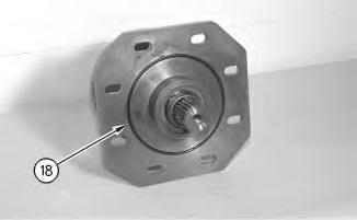
Illustration 8
12. Remove O-ring seal (18) .
13. Repeat Steps 1 through 12 for the other axle assembly.
Copyright 1993 - 2020 Caterpillar Inc. All Rights Reserved. Private Network For SIS Licensees. Sat Apr 25 09:42:44 UTC+0530 2020
Previous Screen
Product: SKID STEER LOADER
Model: 242 SKID STEER LOADER CMB
Configuration: 216 226 232 242 Skid Steer Loader CMB00001-UP (MACHINE) POWERED BY 3024C, 3034 Engine
Disassembly and Assembly
226 and 242 Skid Steer Loaders Power Train
Chain (Drive) - Install
SMCS - 3261-012
S/N - 5FZ6700-UP
S/N - CMB1-UP
Installation Procedure
NOTICE
Care must be taken to ensure that fluids are contained during performance of inspection, maintenance, testing, adjusting and repair of the product. Be prepared to collect the fluid with suitable containers before opening any compartment or disassembling any component containing fluids.
Refer to Special Publication, NENG2500, "Caterpillar Tools and Shop Products Guide" for tools and supplies suitable to collect and contain fluids on Caterpillar products.
Dispose of all fluids according to local regulations and mandates.
i01785880
Illustration 1 g00577375
1. The front axle assemblies and the rear axle assemblies are driven by different drive chains. The drive chains are installed on Drive Sprocket (B) and Drive Sprocket (D). The drive sprockets are mounted on the drive shaft of the hydrostatic piston motor. The two drive sprockets are the same component. The drive sprocket on the hydrostatic piston motor has sprocket drives on different planes. The drive sprockets on the front and rear axles are the same component. The sprockets on the front and rear axles are mounted at 180 degrees of opposite direction. Note that Sprocket (A) is in line with Drive Sprocket (D) and that Sprocket (C) is in line with Drive Sprocket (B). The drive sprockets are installed in a manner that will allow the drive chains to turn in a straight line. If any of the sprockets are installed incorrectly the drive chains can not be installed properly. Note the orientation of all of Drive Sprocket (B) and Drive Sprocket (D). Note the orientation of Sprocket (A) and Sprocket (C) on the axles.
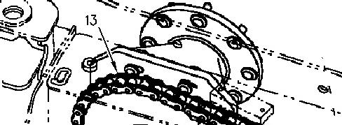

Illustration 2 g00913436
2. Install drive chain assembly (13) .
3. Repeat Step 2 for the other drive chain assembly.
4. Install the spacer. Refer to Disassembly and Assembly, "Piston Motor (Hydrostatic) - Install". Refer to Step 6 through Step 12.
5. Refill the drive chain oil. Refer to Operation and Maintenance Manual, SEBU7468, "Drive Chain Case Oil - Change".
End By:
a. Install the tire and rim. Refer to Disassembly and AssemblyRENR4838, "Tire and RimRemove and Install".
b. Tilt the cab. Refer to Disassembly and AssemblyRENR4838, "Cab - Tilt". Copyright 1993 - 2020 Caterpillar Inc. All Rights Reserved.
Network For SIS Licensees. Sat Apr 25 09:44:06 UTC+0530 2020
Previous Screen
Product: SKID STEER LOADER
Model: 242 SKID STEER LOADER CMB
Configuration: 216 226 232 242 Skid Steer Loader CMB00001-UP (MACHINE) POWERED BY 3024C, 3034 Engine
Disassembly and Assembly
226 and 242 Skid Steer Loaders Power Train
Chain (Drive) - Remove
SMCS - 3261-011
S/N - 5FZ6700-UP
S/N - CMB1-UP
Removal Procedure
Start By:
A. Tilt the cab. Refer to Disassembly and Assembly, "Cab - Tilt".
i01786280
B. Remove the tire and rim. Refer to Disassembly and Assembly, "Tire and Rim - Remove and Install".
C. Drain the drive chain oil. Refer to Disassembly and Assembly, "Piston Motor (Hydrostatic)Remove". Refer to Step 1 through 9.
NOTICE
Care must be taken to ensure that fluids are contained during performance of inspection, maintenance, testing, adjusting and repair of the product. Be prepared to collect the fluid with suitable containers before opening any compartment or disassembling any component containing fluids.
Refer to Special Publication, NENG2500, "Caterpillar Tools and Shop Products Guide" for tools and supplies suitable to collect and contain fluids on Caterpillar products.
Dispose of all fluids according to local regulations and mandates.
Note: Put identification marks on all hoses, on all hose assemblies, on all wires, and on all tube assemblies for installation purposes. Plug all hose assemblies and all tube assemblies. This helps to prevent fluid loss, and this helps to keep contaminants from entering the system.
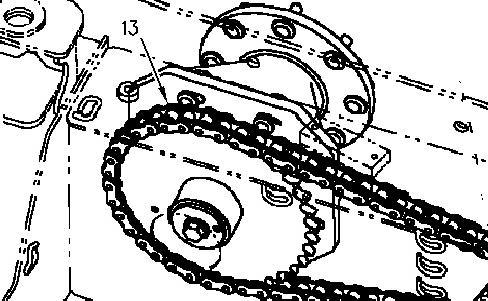
Illustration 1 g00913436
1. Remove drive chain assembly (13) .
2. Repeat Step 1 for the other drive chain assembly.
Copyright 1993 - 2020 Caterpillar Inc. All Rights Reserved. Private Network For SIS Licensees. Sat Apr 25 09:43:50 UTC+0530 2020