


Product: SKID STEER LOADER
Model: 236D SKID STEER LOADER SEN
Configuration: 236D Skid Steer Loader SEN00001-UP (MACHINE)
Disassembly and Assembly
Air Conditioning and Heating R134a for All Caterpillar Machines Media Number -SENR5664-31
Air Conditioner Lines - Remove and Install
SMCS - 1808-010
Personal injury can result from contact with refrigerant. This system isunder pressure at all times, evenif the engine is not running. Heat should never be applied to a charged system.
Contact withrefrigerant can cause frost bite. Keep face and hands away to help prevent injury.
Protective gogglesmust alwaysbe worn whenrefrigerant linesare opened, even if the gauges indicate the system isempty of refrigerant.
Always use caution when a fitting is removed. Slowly loosenthe fitting. If the system isstill under pressure, evacuate the system recovering the refrigerant before removing the fitting.
Personal injury or death can result from inhaling refrigerant througha lit cigarette.
Inhaling air conditioner refrigerant gas througha lit cigarette or other smoking method or inhaling fumes released from a flame contacting air conditioner refrigerant gas, can cause bodily harm or death.
Do not smoke whenservicing air conditionersor wherever refrigerant gas may be present.
Before any checks of the air conditioning and heating system are made, move the machine to a smooth horizontal surface. Lower all implements to the ground. Make sure the transmission is in neutral or park and that
the parking brake is engaged. Keepall other personnel away from the machine or where they can be seen.
Personal injury can result from hot coolant. Any contact with hot coolant or withsteam cancause severe burns. Allowcooling system components to cool before the cooling system is drained.
NOTICE
Never weld or solder any charged components.
Care must be taken during removal of air conditioner lines. Before disconnecting any tube fittings, refer to Testing and Adjusting, "Refrigerant Recovery"in order to recover all refrigerant from the system.
Place dust caps on all hoses and fittings upon disconnecting.
Do not fold or twist hoses when you are routing the new hosesonto the machine. Damage can occur to the inner layers of the hoses and damage can cause premature failure.
Reassemble fittings by using the correct torque values for assembly of the air conditioning unit. Refer to Specifications, SENR3130, "Torque Specifications"in order to find the correct torque value.
Use the following procedure to reassemble the connections.
Proper Technique for Assembly
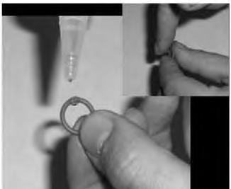
1
1. Drip clean mineral oil onto the clean O-ring.
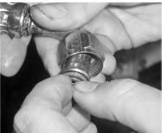
Illustration 2
2. Place the O-ring on fitting.
g01519286
3
3. Oil the O-ring again.
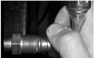
Illustration 4
4. Align fittings and ensure that the seal is seated correctly. Hand tighten the fittings together.
Note: DO NOT CROSS THREAD.

5. Tighten the connection with proper torque. Use a wrench to avoid twisting parts.
Copyright 1993 - 2020 Caterpillar Inc. All Rights Reserved. Private Network For SIS Licensees.
Mon Jun 22 13:54:40 UTC+0530 2020
Product: SKID STEER LOADER
Model: 236D SKID STEER LOADER SEN
Configuration: 236D Skid Steer Loader SEN00001-UP (MACHINE)
Disassembly and Assembly
Air Conditioning and Heating R134a for All Caterpillar Machines
Media Number -SENR5664-31
General Information
SMCS - 1808; 7309
Refrigeration System
Personal injury can result from contact with refrigerant.
This system isunder pressure at all times, evenif the engine is not running. Heat should never be applied to a charged system.
Contact withrefrigerant can cause frost bite. Keep face and hands away to help prevent injury.
Protective gogglesmust alwaysbe worn whenrefrigerant linesare opened, even if the gauges indicate the system isempty of refrigerant.
Always use caution when a fitting is removed. Slowly loosenthe fitting. If the system isstill under pressure, evacuate the system recovering the refrigerant before removing the fitting.
Personal injury or death can result from inhaling refrigerant througha lit cigarette.
Inhaling air conditioner refrigerant gas througha lit cigarette or other smoking method or inhaling fumes released from a flame contacting air conditioner refrigerant gas, can cause bodily harm or death.
Do not smoke whenservicing air conditionersor wherever refrigerant gas may be present.
Before any checks of the air conditioning and heating system are made, move the machine to a smooth horizontal surface. Lower all implements
to the ground. Make sure the transmission is in neutral or park and that the parking brake is engaged. Keepall other personnel away from the machine or where they can be seen.
Personal injury can result from hot coolant. Any contact with hot coolant or withsteam cancause severe burns. Allowcooling system components to cool before the cooling system is drained.
• All refrigerant lines that are metal or flexible hose must be free of sharp bends. Also, do not use a refrigerant line that iskinked. Sharp bends will cause a restriction in the refrigerant flow. Restrictions in the refrigerant lines are identified by cold spots or frost on the line at the location of the restriction. Restrictionsin the lines reduce the performance and the efficiency of the system.
• The radiusof bendsin the flexible hose must never be lessthan ten times the outside diameter of the hose.
• Do not allow the flexible hoses to come within 63.5 mm (2.50 inch) of the exhaust manifold.
• The hoses need to be inspected yearly for leaks and for hardness. Conduct a leak test on all the hoses and the lines. Refer to the Testing and Adjusting, "Refrigerant Leakage - Test" section. Replace hoses if leaks or hardness are in the hoses. Replace hoses with new hose that issealed and free of contaminants.
• The correct use of wrenches is important when connections are made. The type of wrench that isused isalso important. Only use wrenches that are made for use with tube-type fittings. When a hose isconnected or disconnected from the system, use a wrench on the fitting and use a wrench on the nut. When a metal line is connected or disconnected from the system, use a wrench on the fitting and use a wrench on the nut.
• Install protective plugsor protective caps on all components and hoses that are disconnected or removed.
• O-ring seals and O-ring seats must be in good condition. Small cuts, scratches, or particles of dirt will cause a leak in the system. Put new mineral oil (397-7507) on all newO-ring seals at the time of installation. Do not use any sealant on connections.
• Dust capson the compressor block fittings are the primary seals on the air conditioning system.
• All machines should have an identification tag that specifies the refrigerant charge for the machine. The tag should be located in the operator compartment.
• If water is in the vents, check the non-return valve. If water leaks from the air conditioning system, check the non-return valve. The non-return valve should have the proper position and the proper direction.
• If engine coolant is leaking into the operator compartment, check for loose clamps on the heater hoses. Copyright 1993 - 2020 Caterpillar Inc. All Rights Reserved.
Network For SIS Licensees. Mon Jun 22 13:53:44 UTC+0530 2020
Product: SKID STEER LOADER
Model: 236D SKID STEER LOADER SEN
Configuration: 236D Skid Steer Loader SEN00001-UP (MACHINE)
Disassembly and Assembly
Air Conditioning and Heating R134a for All Caterpillar Machines Media
In-Line Refrigerant Dryer - Remove and Install
SMCS - 7322-010-QT
Dryer Installation
Personal injury can result from contact with refrigerant.
This system isunder pressure at all times, evenif the engine is not running. Heat should never be applied to a charged system.
Contact withrefrigerant can cause frost bite. Keep face and hands away to help prevent injury.
Protective gogglesmust alwaysbe worn whenrefrigerant linesare opened, even if the gauges indicate the system isempty of refrigerant.
Always use caution when a fitting is removed. Slowly loosenthe fitting. If the system isstill under pressure, evacuate the system recovering the refrigerant before removing the fitting.
Personal injury or death can result from inhaling refrigerant througha lit cigarette.
Inhaling air conditioner refrigerant gas througha lit cigarette or other smoking method or inhaling fumes released from a flame contacting air conditioner refrigerant gas, can cause bodily harm or death.
Do not smoke whenservicing air conditionersor wherever refrigerant gas may be present.
Before any checks of the air conditioning and heating system are made, move the machine to a smooth horizontal surface. Lower all implements
to the ground. Make sure the transmission is in neutral or park and that the parking brake is engaged. Keepall other personnel away from the machine or where they can be seen.
Personal injury can result from hot coolant. Any contact with hot coolant or withsteam cancause severe burns. Allowcooling system components to cool before the cooling system is drained.
NOTICE
Never weld of solder any charged components.
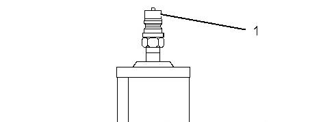
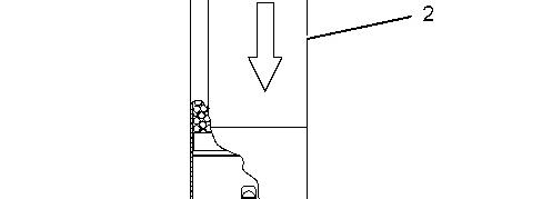


Illustration 1 g01520430
TypicalIn-Line Dryer withquick disconnects
(1) Inlet hose with air conditioner quick disconnect
(2) Dryer
(3) Outlet hose with air conditioner quick disconnect
Note: Replace dryer (2) annually. Dryer (2) should also be replaced whenever the system is opened.
Disassembly and Assembly
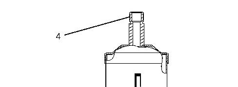
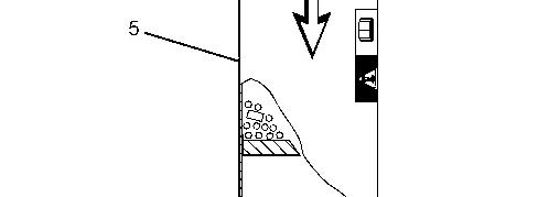
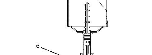

Illustration 2
In-line dryer without quickdisconnects
(4) Inlet hose without air conditioner quick disconnect
(5) Dryer
(6) Outlet hose without airconditionerquickdisconnects
g01520434

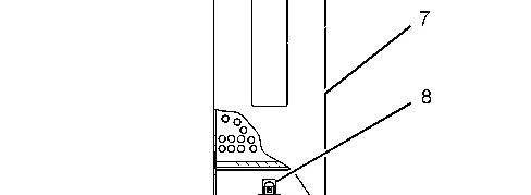


Illustration 3 g03549076
320-0562 Refrigerant DryerAs (7) Dryer (8) Air conditioner orifice assembly
Note: Every 2 yearsreplace dryer (5) and (7) . Dryer (5) and (7) should also be replaced whenever the system isopened.
Before removing the dryer, perform the following steps in order to diagnose the problem
1. Check the following componentsfor blockages: Condenser Evaporator
2. Check the condition and the tension of the compressor drive belt.
3. Connect a manifold gauge set to the compressor. Refer to Testing and Adjusting, "Manifold Gauge Set (Refrigerant) - Install".
4. Operate the Air conditioning.
Operate the engine at 1400 rpm.
Place the air conditioning switch in the ON position.
Set the blower switch to the HIGH position.
Open all of the louversin the cab.
Close the cab doors and close all of the cab windows.
5. Compare the pressures for the manifold gauge to the pressure ranges in Table 1 in order to ensure that the pressures are normal for the current ambient air temperature.
Table 1
Pressure Range (1)
Ambient Air Temperature C°(F°)
High Pressure Test Fitting kPa (psi) (2) (3)
21°C (70°F) 820 to 1300 kPa (120 to 190 psi)
to 1450 kPa (140 to
Low Pressure Test Fitting kPa (psi) (4) (5)
to 138 kPa (10 to 20 psi) 27°C (80°F)
32°C (90°F) 1175 to 1650 kPa (170 to 240 psi)
to 210 kPa (15 to 30 psi)
38°C (100°F) 1300 to 1850 kPa (190 to 270 psi) 105 to 210 kPa (15 to 30 psi)
43°C (110°F) 1450 to 2075 kPa (210 to 300 psi) 105 to 210 kPa (15 to 30 psi)
( 1) This tableis only for reference.
( 2) Pressure maybe slightly higher inhumid conditions and lower in dry conditions.
( 3) With AC High-pressure Test Fittingis located nearthe Evaporator Inlet pressure readingwill be 83 to 103 kPa (12 to 15psi) lower.
( 4) Pressure before clutch disengagement.
( 5)
With AC Low-pressure Test Fittingis located near theEvaporatorOutlet pressure readingwill be 14 to 21 kPa (2 to 3 psi) higher.
6. Check for frost at the dryer outlet.
Note: Moisture on the drier outlet tube after the orifice is normal and this moisture does not indicate a failure with the dryer. Frost on the drier outlet tube after the orifice isan indicator of a low refrigerant charge.
7. If frost isindicated at the dryer outlet or if pressuresare low, proceed to Step 8. Otherwise, proceed to Step 15.
8. Recover the refrigerant charge from the machine. Refer to Disassembly and Assembly, "Refrigerant System Recovery".
9. Record the amount of refrigerant and oil that isrecovered from the Air Conditioner system.
These values will be needed in order to calculate the amount of oil that is needed. Refer to Testing and Adjusting, "Refrigerant Compressor Oil - Test" Section.
10. If the charge was low, check the system for leaks.
a. Use an Ultraviolet light and use an electronic leak detector. Ensure that the following itemsare checked:
Quick disconnects which are on the dryer
Check the drier swivel nut and tighten the nut to 27 ± 4 N·m (20 ±3 lb ft).
All the connections in the circuit that are O-ring
Hoses for rubbing, bulging, and wet spots (oil leaks)
Note: In order to help reveal leaks, simulate the vibrations which are made by the machine by moving the connections.
11. Recharge the refrigerant. Refer to Testing and Adjusting, "Refrigerant System - Charge" Section.
12. Retest the system with the engine at 1400 rpm and check for frost at the dryer outlet.
13. Ensure that the pressures are normal for the current ambient temperature.
14. Refer to Table 1 for the pressures which are normal for the current ambient air temperature.
15. If a component is leaking, bill the claim against the leaking component and provide details in the description.
Dryer Removal
If the dryer does not have air conditioner quick Disconnects, the refrigerant that isin the system must be recovered. Refer to the Testing and Adjusting, "Refrigerant System Recovery"section before you remove the dryer.
If the dryer has air conditioner quick disconnects, use the procedure that follows.
Refer to Disassembly and Assembly, "Machine Preparation for Disassembly and Assembly" before service is performed on the air conditioning system.
1. Stop the engine for 5 minutes to allow the air conditioning system to equalize the pressure.
2. Disconnect the inlet hose from the old dryer.
3. Connect the hose that was disconnected in Step 2 to the inlet on the new dryer.
Note: For a dryer that has air conditioner quick disconnects, do not add additional oil or refrigerant to the system.
4. Start the engine. Operate the air conditioning system for 1 minute.
5. With the air conditioning system in operation, disconnect the outlet hose from the old dryer. Disconnect the old dryer.
6. Stop the engine for 5 minutes to allow the air conditioning system to equalize pressure.
7. Connect the outlet hose that was disconnected in Step 6 to the newdryer.
8. Mark the new dryer in permanent marker Installed mm/dd/yy to assist in future maintenance of the in-line dryer.
Product: SKID STEER LOADER
Model: 236D SKID STEER LOADER SEN
Configuration: 236D Skid Steer Loader SEN00001-UP (MACHINE)
Disassembly and Assembly
Air Conditioning and Heating R134a for All Caterpillar Machines Media Number -SENR5664-31
Machine Preparation for Disassembly and Assembly
SMCS - 7320-017
Personal injury can result from contact with refrigerant.
This system isunder pressure at all times, evenif the engine is not running. Heat should never be applied to a charged system.
Contact withrefrigerant can cause frost bite. Keep face and hands away to help prevent injury.
Protective gogglesmust alwaysbe worn whenrefrigerant linesare opened, even if the gauges indicate the system isempty of refrigerant.
Always use caution when a fitting is removed. Slowly loosenthe fitting. If the system isstill under pressure, evacuate the system recovering the refrigerant before removing the fitting.
Personal injury or death can result from inhaling refrigerant througha lit cigarette.
Inhaling air conditioner refrigerant gas througha lit cigarette or other smoking method or inhaling fumes released from a flame contacting air conditioner refrigerant gas, can cause bodily harm or death.
Do not smoke whenservicing air conditionersor wherever refrigerant gas may be present.
Before any checks of the air conditioning and heating system are made, move the machine to a smooth horizontal surface. Lower all implements to the ground. Make sure the transmission is in neutral or park and that
the parking brake is engaged. Keepall other personnel away from the machine or where they can be seen.
Personal injury can result from hot coolant. Any contact with hot coolant or withsteam cancause severe burns. Allowcooling system components to cool before the cooling system is drained.
NOTICE
Never weld or solder any charged components.
Note: Before you conduct a performance check, refer to the Troubleshooting, "Visual Inspection (Troubleshooting)" section.
Note: Refer to the Troubleshooting, "Machine Preparation for Troubleshooting" section before service work is performed on the air conditioning system.
When the service work isdone on the air conditioning system, the service work must keep the system clean and free from contamination. Plugs and capsmust be used in order to close the componentsand hoseswhen the components and hoses are open. The plugs and capsprotect the system from dirt and air (moisture). Only new refrigerant oil of the correct viscosity and new refrigerant can be added to the system. For the correct oil, refer to the Specifications section of this manual. Any other material or any other substance isconsidered non-condensable and the material will contaminate the system. Keep the work area clean.
• Dust capson the refrigerant compressor block fitting are the primary seal on the air conditioning system.
• All machines should have an identification tag in the cab that specifies the proper refrigerant charge for the machine.
When replacement or repair of components and hoses are required, perform the following procedure:
1. Remove the refrigerant charge. Measure the amount of oil recovered. Refer to the Testing and Adjusting, "Refrigerant Recovery" and Testing and Adjusting, "Refrigerant Oil - Test" section, for proper procedures.
2. Remove the component or remove the hose that is being repaired or replaced. Install protective plugson componentsor hoses that are left exposed to the air.
3. Replace any damaged component or hose.
4. Use the following table in order to determine the amount of oil that is lost during individual replacements of components. Follow the processprovided in Testing and Adjusting, "Refrigerant Oil - Test" to calculate the correct amount of oil needed for the system.
Table 1
Oil Capacitiesfor Component Replacements
Accumulator
Compressor
Condenser
Evaporator
In-Line Dryer (1) before any oil is installed
Receiver-Dryer
30 mL (1 fl oz)
Refer to the Testing and Adjusting, "Refrigerant Compressor Oil - Check"section.
30 mL (1 fl oz)
90 mL (3 fl oz)
30 mL (1 fl oz)
30 mL (1 fl oz)
( 1) Refer tothe Disassembly andAssembly, "InLine Refrigerant Dryer - Remove and Install"
5. Refer to the Testing and Adjusting, "Refrigerant System - Evacuate"section.
6. Refer to the Testing and Adjusting, "Refrigerant System - Charge" section.
Product: SKID STEER LOADER
Model: 236D SKID STEER LOADER SEN
Configuration: 236D Skid Steer Loader SEN00001-UP (MACHINE)
Disassembly and Assembly
Air Conditioning and Heating R134a for All Caterpillar Machines
Media
-SENR5664-31
Refrigerant Accumulator - Remove and Install
SMCS - 1808-010-ZJ; 7320-010-ZJ
The refrigerant must be recovered before the accumulator isremoved. Refer to the Testing and Adjusting, "Refrigerant Recovery" section.
Remove the accumulator. The accumulator hasan internal oil drain hole which could become plugged. The oil could be trapped inside the accumulator. It isnecessary to check for excessive oil when the accumulator ischanged. Add the same amount of oil that was drained from the old accumulator. Add an additional 30 mL (1 fl oz) to the new accumulator before the new accumulator is installed. Do not add oil if the compressor waschanged also. Evacuate the system and recharge the system. Refer to the Testing and Adjusting, "Refrigerant System - Evacuate" section. Refer to the Testing and Adjusting, "Refrigerant System - Charge" section.
Note: If the accumulator hasfrost on the outside, the air conditioning system still contains refrigerant.
Copyright 1993 - 2020 Caterpillar Inc. All Rights Reserved.
Private Network For SIS Licensees.
Mon Jun 22 13:58:31 UTC+0530 2020
Product: SKID STEER LOADER
Model: 236D SKID STEER LOADER SEN
Configuration: 236D Skid Steer Loader SEN00001-UP (MACHINE)
Disassembly and Assembly
Air Conditioning and Heating R134a for All Caterpillar Machines
Media Number -SENR5664-31
Publication Date -01/05/2015 Date Updated -23/10/2018
Refrigerant Compressor - Remove and Install
SMCS - 1802-010 Removal
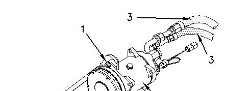

Illustration 1 g00742981
(1) Bolt
(2) Drive belt
(3) Suction and discharge hoses
(4) Compressor
i05907622
1. Remove the refrigerant charge. Refer to the Testing and Adjusting, "Refrigerant Recovery" section.
2. Disconnect electrical wiresfrom the magnetic clutch.
3. Loosen all the mounting bolts and loosen the belt tightener (if equipped). Remove drive belt (2) .
4. Disconnect hoses (3) and put plugs or caps on the hoses. Put plugsor caps on the fittingsof the compressor. Put identification marks on the hoses. The marks will ensure that the hoses will be connected correctly at a later time.
5. Remove all the mounting boltsand remove the compressor (4) . The weight of the compressor is approximately 18 kg (40 lb).
Installation
1. Check the amount and condition of the oil in the compressor (4) . Refer to the Testing and Adjusting, "Refrigerant Compressor Oil-Test" section.
2. Inspect the drive belt (2) . If the drive belt (2) is damaged or worn replace the belt.
3. Install the compressor (4) . Do not tighten the mounting bolts until drive belt (2) isinstalled and adjusted.
4. Connect the discharge and the suction hoses(3) to the discharge and suction portson the compressor.
5. Connect the electrical wires to the magnetic clutch.
6. Evacuate the system. Refer to the Testing and Adjusting, "Refrigerant System - Evacuate" section.
7. Charge the system. Refer to the Testing and Adjusting, "Refrigerant System - Charge" section.
8. For the correct system operation, refer to the Troubleshooting Section in thismanual.
Note: Refer to the Specifications, "Refrigerant Compressor"in the Section for the correct belt tension.
9. For the oil level in the system, refer to Service Manual, "Refrigerant Compressor OilCheck".
Copyright 1993 - 2020 Caterpillar Inc. All Rights Reserved.
Private Network For SIS Licensees. Mon Jun 22 13:57:39 UTC+0530 2020
Product: SKID STEER LOADER
Model: 236D SKID STEER LOADER SEN
Configuration: 236D Skid Steer Loader SEN00001-UP (MACHINE)
Disassembly and Assembly
Air Conditioning and Heating R134a for All Caterpillar Machines Media Number -SENR5664-31
Refrigerant Expansion Valve - Remove and Install
SMCS - 7320-010-EV
To replace the expansion valve, use the procedure that follows. Refer to Service Manual, "Troubleshooting Heating and Air Conditioning Control System" before service work is performed on the air conditioning system.
1. Recover the refrigerant.
Note: Cap all disconnected lines and hoses.
2. Remove the insulation and the clip. The insulation and the clip hold the sensing bulb to the evaporator outlet pipe.
3. Disconnect the sensing line for pressure from the evaporator outlet pipe.
4. Loosen and remove the two connections at the expansion valve. Remove the expansion valve.
Note: Check the O-ring seals. The seals must be in good condition and the seals must be properly lubricated with the correct refrigerant oil before assembly.
5. Install the expansion valve for replacement and tighten the two connections.
6. Tighten the pressure sensing connection on the evaporator outlet pipe.
7. Use a 8P-6355 Clip to hold the sensing bulb onto the evaporator outlet pipe. The sensing bulb should be as close to the coil as possible. The bulb should be upstream of the pressure sensing connection on the evaporator outlet pipe. The 5P-7070 Insulation should be wrapped tightly around the clip, the sensing bulb, and the outlet pipe. There should be no insulation between the bulb and the outlet pipe.
8. Tighten all the connections correctly.
9. Evacuate the system. Refer to the Testing and Adjusting, "Refrigerant System - Evacuate" section.
10. Charge the system with the correct amount of refrigerant by weight. Refer to the Testing and Adjusting, "Refrigerant System - Charge" section.
Copyright 1993 - 2020 Caterpillar Inc. All Rights Reserved. Private Network For SIS Licensees.
Mon Jun 22 13:58:50 UTC+0530 2020
Product: SKID STEER LOADER
Model: 236D SKID STEER LOADER SEN
Configuration: 236D Skid Steer Loader SEN00001-UP (MACHINE)
Disassembly and Assembly
Air Conditioning and Heating R134a for All Caterpillar Machines
Media Number -SENR5664-31
Refrigerant Orifice Tube Assembly - Remove and Install
SMCS - 7320-010-QT
The orifice tube may be located in the refrigerant line near the evaporator inlet, or in the in-line dryer.
If the orifice tube is located in the refrigerant line near the evaporator inlet, use the procedure that follows. If the orifice tube is located in the in-line dryer, refer to Dryer Replacement.
Removing the Orifice Tube
Refer to Safety Requirements before service work is performed on the air conditioning system.
The refrigerant must be recovered before removing the accumulator. Refer to the Testing and Adjusting, "Refrigerant Recovery" section.
NOTICE
Do not attempt to remove the orifice tube with pliers. Do not twist or rotate the orifice tube in the tube assembly.
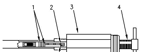
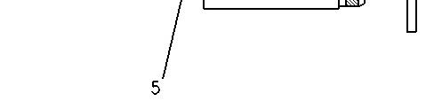
Illustration 1 g00379603
Orifice tube
(1) O-Ring seals
(2) Lugs
(3) Body
(4) Drive screw
(5) Finger lock
1. Disconnect the high side line at the enlarged section of the evaporator inlet port. Thiswill expose the orifice tube for removal.
2. Align the short fingers of the 1U-9890 Orifice Removal Tool with the ribs of the orifice tube. Insert the tool onto the tube until the tool bottoms out.
3. Turn drive screw(4) clockwise. Turn far enough to engage the lugs(2) on the orifice tube in the finger lock (5) . The finger lock (5) ispart of the removal tool.
4. Hold the drive screw (4) stationary. Thread the body (3) forward until the body makes contact with the inlet port.
5. Continue holding the drive screwstationary, and thread the body forward until the orifice tube becomes free.
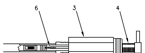
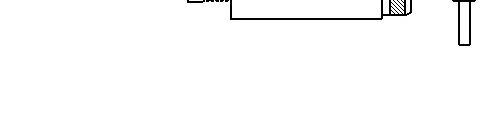
Illustration 2 g00381412
Removing the broken orificetube
(3) Body
(4) Drive screw
(6) Extractor tip
6. For the removal of the orifice tube assembly, use the extractor tip (6) on 1U-9890 Orifice Removal Tool . Insert the tool into the evaporator inlet tube and thread the tool into the brass center of the orifice tube.
7. Repeat steps 3 and 4.
8. If only the brass center of the orifice tube is removed, thread the tool into the plastic body and repeat step 3 and 4.
Orifice Tube Installation
1. Lubricate the O-Ring on the orifice tube with the proper clean refrigerant oil.
2. Place the orifice tube into the 1U-9890 Orifice Removal Tool . Insert the orifice tube straight into the evaporator inlet tube without twisting until the tube is seated.
3. Disengage the removal tool from the orifice tube.
4. Use a newO-Ring that is lubricated with clean refrigerant oil. Reconnect the high side line at the enlarged section of the evaporator inlet port.
5. Do a leak test. Evacuate the system and recharge the system. Refer to the Testing and Adjusting, "Refrigerant Systems-Evacuate" section. Also, refer to the Testing and Adjusting, "Refrigerant Systems-Charge" section.