

236D3 SKID STEER LOADER


Product: SKID STEER LOADER
Model: 236D3 SKID STEER LOADER AZ6
Configuration: 236D3 Skid Steer Loader AZ600001-UP (MACHINE) POWERED BY C3.3B Engine
Disassembly and Assembly
253D3, 279D3, 289D3 Compact Track Loaders and 257D3 Multi Terrain Loader and 236D3, 242D3, 246D and 262D3 Skid Steer Loaders Engine Supplement
Media Number -M0097942-00 Publication Date -01/07/2013 Date Updated -08/11/2019
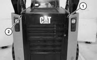
Air Cleaner - Remove and Install
SMCS - 1051-010
Removal Procedure
Hot engine components can cause injury from burns. Before performing maintenance on the engine, allow the engine and the components to cool.
i05366406
2
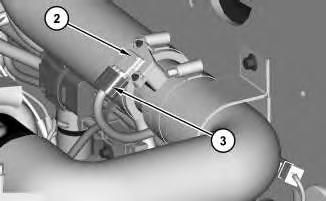
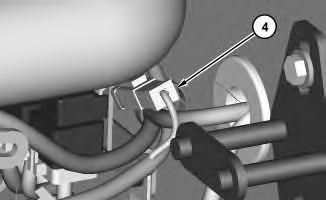
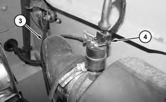
2. Disconnect hose (3) and harness assembly (4).
3
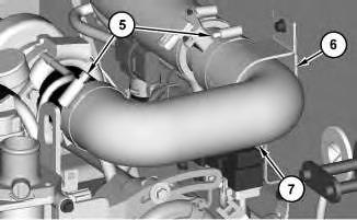
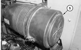
3. Remove cover (5).
4
This is the sample of the manual click on the download link for complete manual
For some reason if link does not work download this pdf and then click
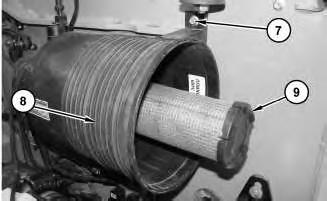
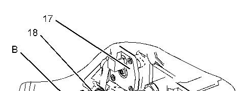
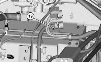
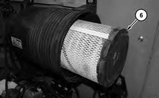
4. Remove filter element (6) and filter element (9).
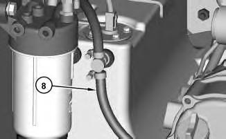
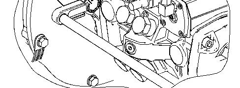
5. Remove bolts (7) and air cleaner housing (8).
Installation Procedure
1. Install air cleaner housing (8) in the reverse order of removal.
Copyright 1993 - 2025 Caterpillar Inc. All Rights Reserved. Private Network For SIS Licensees.
Wed Mar 12 16:26:38 UTC+0700 2025
Product: SKID STEER LOADER
Model: 236D3 SKID STEER LOADER AZ6
Configuration: 236D3 Skid Steer Loader AZ600001-UP (MACHINE) POWERED BY C3.3B Engine
Disassembly and Assembly
253D3, 279D3, 289D3 Compact Track Loaders and 257D3 Multi Terrain Loader and 236D3, 242D3, 246D and 262D3 Skid Steer Loaders Engine Supplement Media
Alternator - Remove and Install
SMCS - 1405-010
Removal Procedure
1. Refer to Operation and Maintenance Manual, "Belts - Inspect/Adjust/Replace".
i05238497
2. Refer to Operation and Maintenance Manual, "Battery or Battery Cable - Inspect/Replace".
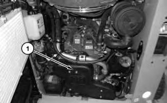
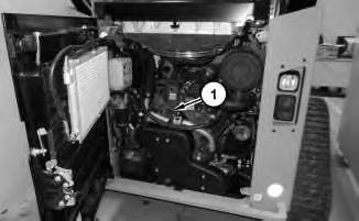
Illustration 1
3. Remove cover (1).
g03341869
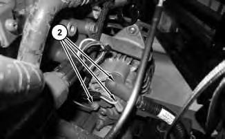
2
4. Disconnect harness assemblies (2).
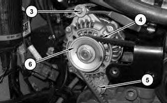
3
5. Loosen bolt (3). Remove belt (4), remove bolt (5), and alternator (6).
Installation Procedure
1. Install alternator (6) in the reverse order of removal.
Copyright 1993 - 2025 Caterpillar Inc. All Rights Reserved. Private Network For SIS Licensees.
Product: SKID STEER LOADER
Model: 236D3 SKID STEER LOADER AZ6
Configuration: 236D3 Skid Steer Loader AZ600001-UP (MACHINE) POWERED BY C3.3B Engine
Disassembly and Assembly
253D3, 279D3, 289D3 Compact Track Loaders and 257D3 Multi Terrain Loader and 236D3, 242D3, 246D and 262D3 Skid Steer Loaders Engine Supplement
Media
i05850694
Battery and Battery Cable - Separate and Connect
SMCS - 1401-029-KA
Removal Procedure
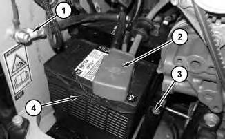
Illustration 1
1. Remove negative battery cable (1) .
2. Disconnect positive battery cable (2) .
3. Remove bracket (3) . Remove battery (4) . The weight of battery (4) is approximately 23 kg (50 lb).
Installation Procedure
1. Install battery (4) in the reverse order of removal.
a. Tighten positive battery cable (2) to a torque of 7 ± 2 N·m (62 ± 18 lb in).
b. Tighten negative battery cable (1) to a torque of 7 ± 2 N·m (62 ± 18 lb in).
Copyright 1993 - 2025 Caterpillar Inc. All Rights Reserved. Private Network For SIS Licensees.
Wed Mar 12 16:23:01 UTC+0700 2025
Product: SKID STEER LOADER
Model: 236D3 SKID STEER LOADER AZ6
Configuration: 236D3 Skid Steer Loader AZ600001-UP (MACHINE) POWERED BY C3.3B Engine
Disassembly and Assembly
253D3, 279D3, 289D3 Compact Track Loaders and 257D3 Multi Terrain Loader and 236D3, 242D3, 246D and 262D3 Skid Steer Loaders Engine Supplement
Media Number -M0097942-00
Cab - Tilt
SMCS - 7301-084
Raising the Cab
Do not go beneath cab unless cab is empty and support lever is engaged.
Failure to follow the instructions or heed the warnings could result in injury or death.
Do not tilt the cab using an open door. The door must be closed and latched when lifting the cab. The door may become dislodged from its hinges and may cause serious personal injury or death.
1. Park the machine on level ground.
2. Remove the interior cab air filter.
3. If you tilt the cab upward with the loader lift arms in the RAISED position, engage the brace for the loader lift arms. Refer to Operation and Maintenance Manual, "Loader Lift Arm Brace Operation" for the process for engaging the brace for the loader lift arms.
4. Close the cab door and ensure that the door is latched.
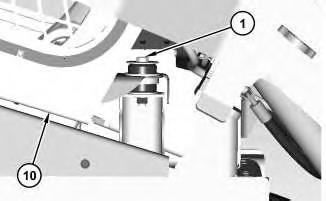
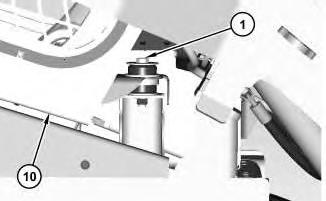
Illustration 1
g02896278
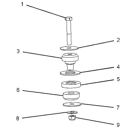
Illustration 2 g02896156
5. Remove bolt (1). Remove washer (2), rubber mount (3), washer (4), spacer (5), rubber mount (6), washer (7), washer (8), and nut (9).
Note: Note the location of the rubber mounts and the spacers for assembly purposes.
6. Raise cab (10).
3
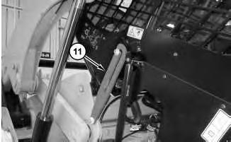
7. Raise the cab until the cab support lever (11) is in the ENGAGED position.
Lowering the Cab
Illustration 4
1. Raise the cab. With the help of another person, release the cab support lever (11).
5
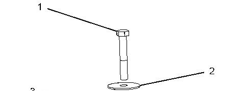
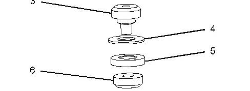
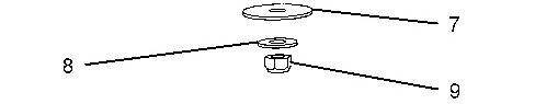
Illustration 6 g02896156
2. Lower cab (10).
3. Install nut (9), washer (8), washer (7), rubber mount (6), spacer (5), washer (4), rubber mount (3), and washer (2). Install bolt (1). Tighten bolts (1) to a torque of 125 ± 10 N·m (92 ± 7 lb ft).
Copyright 1993 - 2025 Caterpillar Inc. All Rights Reserved. Private Network For SIS Licensees. Wed Mar 12 16:27:47 UTC+0700 2025
Product: SKID STEER LOADER
Model: 236D3 SKID STEER LOADER AZ6
Configuration: 236D3 Skid Steer Loader AZ600001-UP (MACHINE) POWERED BY C3.3B Engine
Disassembly and Assembly
253D3, 279D3, 289D3 Compact Track Loaders and 257D3 Multi Terrain Loader and 236D3, 242D3, 246D and 262D3 Skid Steer Loaders Engine Supplement
Media Number -M0097942-00
Publication Date -01/07/2013 Date Updated -08/11/2019
Coolant Tank - Remove and Install
SMCS - 1354-010; 1377-010-TP; 1377-010; 1377
Removal Procedure
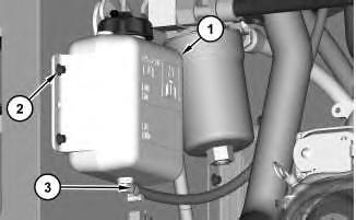
1
1. Disconnect hose (3). Remove bolts (2) to remove expansion tank (1).
Installation Procedure
1. Install expansion tank (1) in the reverse order of removal.
Copyright 1993 - 2025 Caterpillar Inc.
All Rights Reserved.
Private Network For SIS Licensees.
i05350715
Wed Mar 12 16:24:25 UTC+0700 2025
Product: SKID STEER LOADER
Model: 236D3 SKID STEER LOADER AZ6
Configuration: 236D3 Skid Steer Loader AZ600001-UP (MACHINE) POWERED BY C3.3B Engine
Disassembly and Assembly
253D3, 279D3, 289D3 Compact Track Loaders and 257D3 Multi Terrain Loader and 236D3, 242D3, 246D and 262D3 Skid Steer Loaders Engine Supplement
Media Number -M0097942-00 Publication Date -01/07/2013 Date Updated -08/11/2019
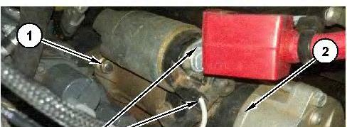
Electric Starting Motor - Remove and Install
SMCS - 1453-010
Removal Procedure
Hot engine components can cause injury from burns. Before performing maintenance on the engine, allow the engine and the components to cool.
i05239136
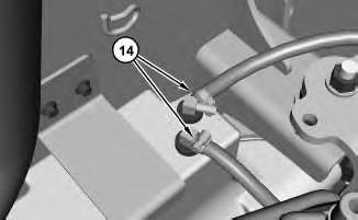
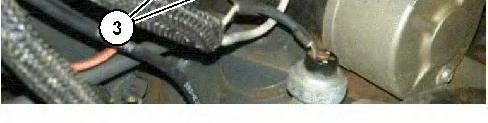
1. Disconnect harness assemblies (3) remove bolts (1), and electric starting motor (2).
Installation Procedure
1. Install electric starting motor (2) in the reverse order of removal.
a. Tighten the nut (Terminal B) for cable assembly (3) to a torque of 10.4 ± 0.6 N·m (92.1 ± 5.3 lb in).
1993 - 2025 Caterpillar Inc. All Rights Reserved.
Product: SKID STEER LOADER
Model: 236D3 SKID STEER LOADER AZ6
Configuration: 236D3 Skid Steer Loader AZ600001-UP (MACHINE) POWERED BY C3.3B Engine
Disassembly and Assembly
253D3, 279D3, 289D3 Compact Track Loaders and 257D3 Multi Terrain Loader and 236D3, 242D3, 246D and 262D3 Skid Steer Loaders Engine Supplement
Electronic Control Module (ECM) - Remove and Install
SMCS - 1901-010; 7600; 7610-010-MCH
Removal Procedure
i05350696
1. Refer to Operation and Maintenance Manual, "Battery or Battery Cable - Inspect/Replace"
2. Refer to Operation and Maintenance Manual, "Radiator Tilting".

Illustration 1
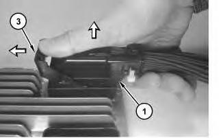
3. Engine harness disconnect procedure.
g02832900
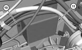
a. Harness connectors (1) are color coded. Put identification marks on the connectors for installation purposes.
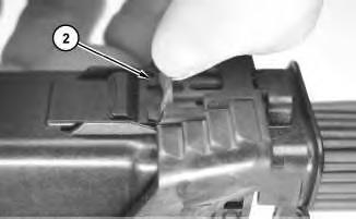
2
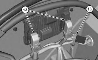
b. Slide connector lock (2) forward.
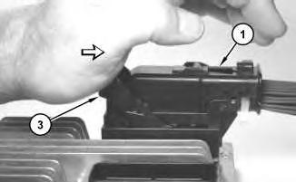
3
c. Push lever (3) forward to the pre-lock position.
Note: The lever must be pushed fully forward to be in the pre-lock position.
d. While pushing lever (3) forward, grip the connector evenly and pull harness connector (1) straight outward.
4
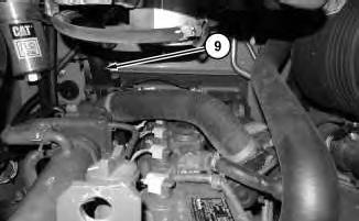
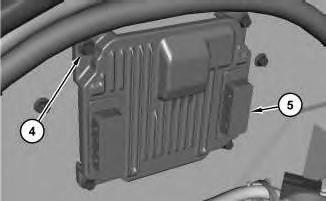
4. Remove bolts (4) to remove electronic control module (5).
Installation Procedure
NOTICE
Review the following procedure before removing and installing the Engine ECM connectors. Do not force the connector onto the ECM. Do not force the lever into the lock. Failure to follow the instructions below will cause damage to the ECM pins, may create various faults, and may require ECM replacement.
1. Position electronic control module (5) and install bolts (4).
6
2. Engine harness connect procedure.
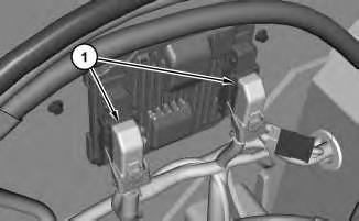
a. Harness connectors (1) are color coded.
7
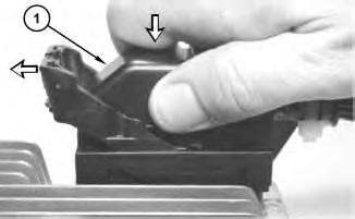
Illustration 8
b. Ensure that the aligning key features of harness connector (1) are aligned with the receptacle on the electronic control module.
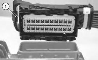
c. Position harness connector (1) and press firmly until lever (3) moves slightly forward.
9
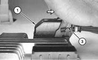
Illustration 10
g02834456
d. Press lever (3) backward until harness connector (1) is fully engaged with the receptacle on the electronic control module.
Note: The lever action should be smooth and continuous. Do not attempt to force the lever or damage to the connector or the electronic control module can occur.
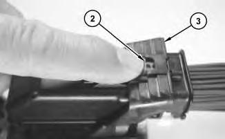
Illustration 11
g02834476
e. Slide connector lock (2) backward to secure lever (3) in place.
Copyright 1993 - 2025 Caterpillar Inc. All Rights Reserved. Private Network For SIS Licensees.
Product: SKID STEER LOADER
Model: 236D3 SKID STEER LOADER AZ6
Configuration: 236D3 Skid Steer Loader AZ600001-UP (MACHINE) POWERED BY C3.3B Engine
Disassembly and Assembly
253D3, 279D3, 289D3 Compact Track Loaders and 257D3 Multi Terrain Loader and 236D3, 242D3, 246D and 262D3 Skid Steer Loaders Engine Supplement
Media Number -M0097942-00 Publication Date -01/07/2013 Date Updated -08/11/2019
Engine - Remove and Install
SMCS - 1000-010; 1002
S/N - AZ61-UP
S/N - CW91-UP
S/N - F9C1-UP
S/N - FMA1-UP
S/N - GK61-UP
S/N - HSX1-UP
S/N - KEZ1-UP
S/N - KXL1-UP
S/N - LM71-UP
S/N - MC91-UP
S/N - ME61-UP
S/N - NXL1-UP
S/N - R2L1-UP
S/N - S7E1-UP
S/N - TE91-UP
S/N - TLS1-UP
i06510920