


Product:TRUCKENGINE
Model:1693TRUCKENGINE65B
Configuration:1693DIESELTRUCKENGINE65B02918-11050
OperationandMaintenanceManual
1693TRUCKENGINE
MediaNumber-SEBU5433-01PublicationDate-01/10/1977DateUpdated-11/10/2001
Product:TRUCKENGINE
Model:1693TRUCKENGINE65B
Configuration:1693DIESELTRUCKENGINE65B02918-11050
OperationandMaintenanceManual
1693TRUCKENGINE
MediaNumber-SEBU5433-01PublicationDate-01/10/1977DateUpdated-11/10/2001
SMCS-1000;1250;1450;1453;1456;1900
Thepurposeoftheairinductionsystemistoprovidecleanairtotheengineinanefficient,silent mannerwhiletheexhaustsystemdischargesexhaustgasesasquicklyandassilentlyaspossible. Enginehorsepowerandefficiencywillbereducedifeithertheairinletorexhaustbecomesrestricted. Goodmaintenancepracticecannotbeoveremphasized.
Regularserviceintervals,alongwithclosevisualinspectionoftheaircleaner,arenecessaryfor propercleaningoftheengineinletair.Theserviceintervalwillvarywiththeweatherandworking conditions.Wheredustconditionsaresevere,itwillbenecessarytoservicetheaircleanerfrequently. Indampweatherandotherconditionsoflittleornodust,theserviceintervalcanbeextended.
Toextendtheservicelifeoftheelement,theexhaustandaircleanerinletpipesshouldbearrangedso thatexhaustand/oroilfumesdonotentertheengineaircleaner.
Visualinspectionofthegasketsandsealsisimportantinkeepingdustfromby-passingtheaircleaner. Anydirtallowedtoenter,accelerateswearthroughouttheengine.Iftheconditionofanyofthe replaceablesealsandgasketsisquestionable,replacethem.Ifthesealingendsofthefilterelementor theelementpleatsaredamaged,replacetheelement.
Extrafilterelementsshouldbekeptonhandforreplacementorforuseintheaircleanerwhilethe elementthatwasremovedisbeingcleaned.
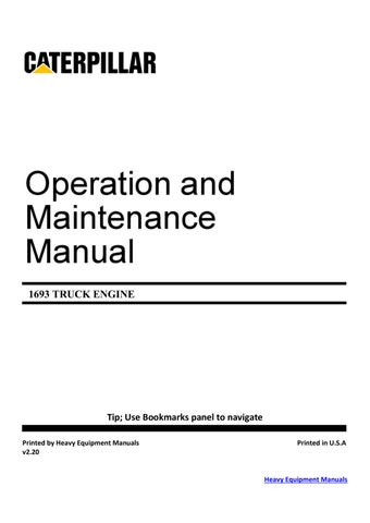
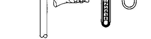
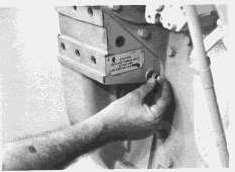
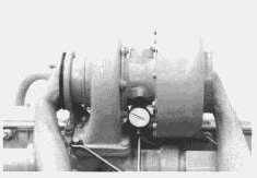
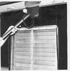
Whenequippedwithadry-typeaircleaner,aserviceindicatorsimilartotheoneshownisavailable.
Theaircleanerserviceindicatorisconnectedtotheairinletpipebetweentheaircleanerandthe turbocharger.Itcontainsaredmarkedpiston,whichgraduallyriseswithrestrictiontotheairflow. Whentheentirepistonisvisibleitwilllockinthisposition.Thisindicatesaneedforaircleaner service.Thepistonwillremaininthispositionwhetherornottheengineisrunning.Afterservicing theaircleaner,resetthepistonbydepressingtheplungerinthebottomoftheindicator.
Excessiveengineexhaustsmokeand/orlossofpowermayindicatetheneedforservicingtheair cleaner.Neverservicetheaircleanerwhiletheengineisrunning.
Every10,000miles(16000km),in averageoperatingconditions,removethefilterelementforinspectionandcleaning.Thisperiodmay beextendedincleanatmosphereandcanonlybedeterminedbyexperience.
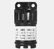
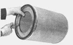
1.Toremovethefilterelement,loosenthewingnut,removetheendcoverandthefilterelement.
2.Inspecttheelementandifitisdamaged,installanewelement.
3.Removeanydirtwhichhasaccumulatedonthebottomofthecaseandcleanthefilterelement usingoneofthemethodscoveredinthetopic,FILTERELEMENTCLEANING.
4.Installthefilterelementandcover.Wheninstallingthefilterelement,theclosedendoftheelement mustbeinstalledagainstthecover.Fastenthecoversecurely.
Ifanairinletrestrictionissuspectedinthepipingorairfilterelement,checkwithadifferential pressuregaugeormanometer.Removetheaircleanerserviceindicatorandconnectdifferential
pressuregaugeormanometerintheserviceindicatorconnection.Theairinletpipingoraircleaner shouldnotrestrictairflowmorethan30inches(762mm)ofwaterdifferenceinpressure.
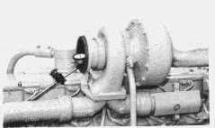
Restrictionoftheexhaustsystem(backpressure)ismeasuredwithadifferentialpressuregaugeor manometer.Thispressuredifferenceismeasuredbetweentheturbochargeroutletandambientairand shouldbenomorethan27inches(686mm)ofwater.Anexhaustpressuretapisprovidedinthe turbochargeroutletelbow.Thischeckshouldbeperformedwiththeengineatoperatingtemperature anddevelopingfullratedpower.
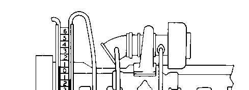
CHECKINGEXHAUSTSYSTEMBACKPRESSURE
FILTERELEMENTCLEANING:(CaterpillarDry-typeFilterElementsOnly-IfOther Manufacturer'sAirCleanerIsUsedReferToTheirRecommendations)
This is the sample of the manual if you need complete manual Click Here to download
Filterelementscanbecleanedseveraltimesbeforereplacing;however,closeinspectionofthe elementshouldbemadewhenreinstallingacleanedelement.
Theendsofafilterelementwillbedamagedbybumpingortapping.Bentand/ordentedendscannot sealproperlyandmayallowunfilteredairtoentertheenginecylindersandcauseprematureengine wear.
Cleanthefilterelementusingoneofthefollowingmethods:
CLEANINGWITHPRESSUREAIR:Usingclean,dryair,atapressurenottoexceed30psi(205 kPa),proceedasfollows:
Holdtheairnozzleatleastoneinchfromtheelementanddirectairatanangleagainsttheinside (engineside)oftheelementtoloosenanyimbeddeddirt.Bestresultscanbeobtainedbymovingthe airhosesothatairisdirectedatananglealongthecompletelengthofeachpleat.
Blowoffloosedirtbydirectingairagainsttheoutsideoftheelement.Repeatthisprocedureuntilthe elementisclean.Makecertainthatnodirtisinsidetheelement.
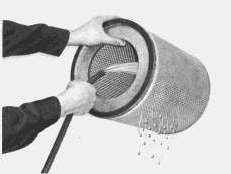
CLEANINGWITHWATER:Usingcleanwater,atapressurenottoexceed40psi(280kPa), proceedasfollows.
Directwateratanangleagainsttheinside(engineside)oftheelementtoloosenanyimbeddeddirt. Bestresultscanbeobtainedbyusingawaterhosewithoutanozzleandmovingitsothatwateris directedatananglealongthecompletelengthofeachpleat.Washoffloosedirtbydirectingwater againsttheoutsideoftheelement.Repeatthisprocedureuntiltheelementisclean.Makecertainthat nodirtisontheenginesideoftheelement,andthoroughlydrytheelementbeforeinstallingit.
CLEANINGWITHDETERGENT:Someoilyand/orsootydepositscanberemovedbywashing theelementinasolutionofwarmwaterandagoodhouseholdnon-sudsingdetergent.Rinsewith cleanwaterandthoroughlydrytheelementbeforeinstallingit.
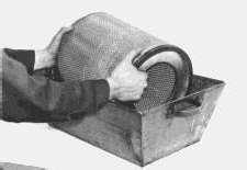
WASHINGELEMENTWITHDETERGENT
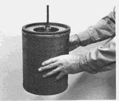
1.Holdalightedelectricbulbinsidethedriedelementandcarefullyinspecttheelementfortiny, pinpointsoflight.Anylightshowingindicatesapleathasrupturedandwilltearwithfurtheruse. Discardtheelement.
2.Wrapusableelementsinsealedplasticbags.
3.Storethewrappedelementinadry,cleanplace.
Whenequippedwithoilbathtypeaircleaners,accumulationofdirtand/oroilintheaircleaneroutlet pipeisanindicationtheaircleanerisnotbeingservicedorfunctioningproperly.Referto manufacturer'srecommendationsforservicing.
Makevalvelashadjustmentevery100,000miles(160000km)withenginestopped.TDCoftheNo. 1pistononthecompressionstrokeisthereferencepoint.No.1pistonisatTDCcompressionstroke whentheNo.1valvesareclosed.
Removethevalvecover.Thefourvalvesatthefrontoftheenginearetheinletandexhaustvalvesfor No.1cylinder.
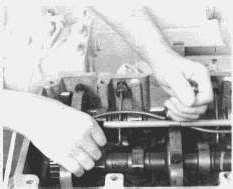
1.Rotatetheflywheelcounterclockwise(asviewedfromtheflywheelendoftheengine)untiltiming boltcanbeinstalledinflywheel.
2.Installthetimingboltthroughtheopeningfortheplugandintothethreadedholeinflywheel.All valvesforNo.1cylindershouldnowbeclosed.
TIMINGBOLTINSTALLATION
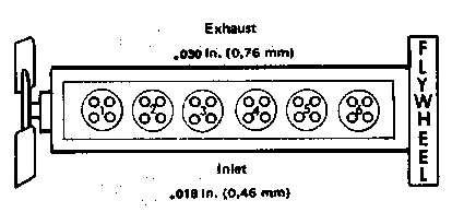
3.WithNo.1pistonatTDCcompressionstroke,adjustlashon1,3and5exhaustand1,2and4inlet valves.
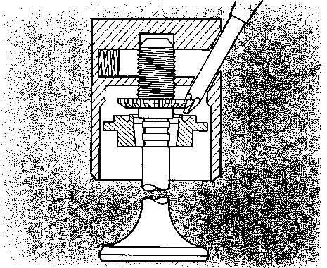
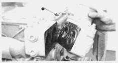
4.Turncamfolloweronvalvebeingadjusteduntiltheslantedholeinthefollowerfacesthecenterof theengine.
5.InsertaPhillipsscrewdriverintheslantedholeandturnscrewdriverclockwisetoincreasevalve lashorcounterclockwisetodecreasethevalvelash.Withaclearancegauge,measurevalvelash betweenthecamfollowerandthecam.Correctvalvelashis.030"(0.76mm)forexhaustvalves and.018"(0.46mm)forinletvalves.
6.Removethetimingboltandturnthecrankshaft360°counterclockwise.Alignflywheeltimingbolt.
7.Adjustlashon2,4and6exhaustand3,5and6inletvalves.
8.Afteradjusting,installthetimingboltandtheplugbackintheiroriginallocations.

Thefollowingprocedureprovidesacheckofthesealingabilityoftheindividualvalvesandpiston ringswithoutremovingthecylinderhead:
1.Removethefuelinjectionnozzlefromthesuspectedcylinder,leavingtheprecombustionchamber inplace.
2.Adaptanairhosetotheprecombustionchamber.Thiscanbedonewitheitherathreadedfittingor byholdingarubberadapterinplace.
3.Rotatethecrankshaftuntilthepistoninthesuspectedcylinderisattopcenter(TC)onthe compressionstroke.Inthispositionthevalvesofthiscylinderareclosed.
Lockenginetopreventrotating.
4.Forceairintothecylinderandthencheckforescapingair.Airescapingfromtheexhaustopening indicatesexhaustvalveleakage.Airescapingfromtheaircleanerinletindicatesinletvalveleakage. Ifairescapesfromthecrankcasebreatherduringthistest,thepiston,ringsand/orlinercanbeatfault.
Itmaybenecessarytoremoveinletandoutletconnectionsonbothsidesoftheturbochargertonotice leakagefrominletand/orexhaustvalves.
Analternateandmoreaccuratemethodofcheckingcompressioncanbemadewiththeuseofanair regulatorvalve,gaugesandanadaptergroup.Authorizeddealershavethenecessaryequipmentand canperformthisserviceforyouorsupplyyouwiththenecessaryinstructions.
Excessivecrankcasepressurecanbearesultofcombustiongasleakingpastbrokenordamaged pistons,worncylinderlinerwallsand/orpistonrings.Thisconditionwillusuallybeaccompaniedby irregularengineoperationandexcessfumesfromcrankcasebreatheropening.Thispressurecancause thebreatherelementtobecomerestrictedinanunusuallyshorttime.Inaddition,itcancauseengine oiltoleakpastgasketsandsealsthatwouldfunctionproperlyundernormalconditions.
Every200,000miles(320000km)ofifanyunusualsoundorvibrationintheturbochargerisnoticed, aquickcheckofbearingconditioncanbemadewithoutdisassemblingtheturbocharger.Thiscanbe donebyremovingthepipingfromtheturbochargerandinspectingthecompressorimpeller,turbine wheelandcompressorcover.Rotatethecompressorandturbinewheelassemblybyhandandobserve byfeelingexcessendplayandradialclearance.Therotatingassemblyshouldrotatefreelywithno rubbingorbinding.Ifthereisanyindicationoftheimpellerrubbingthecompressorcoverorthe turbinewheelrubbingtheturbinehousing,reconditiontheturbochargerorreplacewithanewor rebuiltone.
Endclearanceisbestcheckedwithadialindicator.Attachadialindicatorwiththeindicatorpointon theendoftheshaft.Movetheshaftfromendtoendmakingnoteofthetotalindicatorreading.
Endplayshouldbebetween.004in.(0,076mm)and.009in.(0,203mm).Ifendplayexceeds.009in. (0,203mm)rebuildorreplacetheturbocharger.Endclearancelessthan.004in.(0,076mm)could indicatecarbonbuild-upontheturbinewheelandshouldbedisassembledforcleaningandinspection.
Amorereliablecheckofbearingconditioncanbemadeonlywhentheturbochargerisdisassembled andthebearings,shaftjournalandhousingborediameterscanactuallybemeasured.Thisserviceis availablefromanauthorizeddealer.
Radialclearancecanalsobecheckedwithadialindicator.Removetheoilreturnlinefromthe turbocharger.Attachadialindicatorwithanextensionindicatorpointlongenoughtocontacttheshaft throughtheoilreturnhole.Makesurethecontactpointiscenteredontheshaft(highestindicator reading).Raisebothendsoftheshaftallthewaythenpushdownintheoppositedirection.Total movementoftheindicatorshouldbebetween.005in.(0,13mm)and.009in.(0,23mm).Ifradial clearanceexceeds.009in.(0,23mm)orminimumclearanceisunder.005in.(0,13mm),the turbochargershouldbedisassembledandthebearingschecked.
NOTE:Caremustbetakennottococktheshaftorafalsereadingwillbeobtained.
Ifaturbochargerfails,trytodeterminecauseoffailureandeliminatebeforeinstallingarebuiltornew turbocharger.Wheninstallinganeworrebuiltturbochargeralwaysperformthefollowingsteps.
A.Inspecttheairinductionandexhaustsystemforthepresenceofforeignparticleswhichcould resultinrepeatfailure.
B.Changetheaircleanerelement.
C.Changetheoilfilters.
D.Drainandrefilltheenginecrankcase.
E.Pre-lubricatethereplacementturbochargerbyfillingthecenterhousingwithoil.
TueNov2601:08:46UTC+05302024
Product:TRUCKENGINE
Model:1693TRUCKENGINE65B
Configuration:1693DIESELTRUCKENGINE65B02918-11050
OperationandMaintenanceManual
1693TRUCKENGINE
MediaNumber-SEBU5433-01PublicationDate-01/10/1977DateUpdated-11/10/2001
SMCS-1000;1250;1450;1453;1456;1900
Theengineshouldbeequippedwitharadiatorwhichhasasealedpressureradiatorcapfor pressurizingthecoolingsystem.Pressurizingthecoolingsystemservestwopurposes.First,itpermits safeoperationatcoolanttemperaturehigherthanthenormalboilingpoint;thereby,providinga marginofcoolingthethoseintermittentpeakloads.Secondly,ithelpspreventcavitationinthewater pumpandreducesthepossibilityofairorsteampocketsforminginthecoolantpassages.
COOLANTLEVEL:Checktheenginecoolantleveldaily(withenginestopped).Carefullyrelease coolingsystempressurebeforechecking.Filltotheproperlevelwithpermanent-typeantifreezeand water.Usewaterwhichisfreeaspossiblefromscaleformingminerals,(notsoftenedwater).
INHIBITORCONTAINSALKALI.Avoidcontactwitheyes.Avoid prolongedorrepeatedcontactwithskin.Donottakeinternally.Incase ofcontact,immediatelywashskinwithsoapandwater.Foreyes,flush withlargeamountsofwaterforatleast15minutes.CALL PHYSICIAN.KEEPOUTOFREACHOFCHILDREN.
Beforeplacingtheengineinoperation,makesurea3%concentrationofCaterpillarCorrosion Inhibitororequivalenthasbeenaddedtothecoolingsystem.
NOTICE
DonotusewithDowtherm209.
Every3months,500servicehoursor25,000miles(40,000km)whicheveroccursfirst,addcorrosion inhibitortomaintaintherecommended3%concentration.
Refertotheapplicationchartonthecontainerforinitialfillandmaintenancefillamounts.
Addcoolantslowlytoahotenginetopreventpossiblecrackingor distortingthecylinderhead.
Ifalossofcoolantisnoticeable,checkforleaksinthesystem.Afterfillingthesystem,startthe engineandrecheckthecoolantlevelafternormaloperatingtemperatureisreached.Runningthe engineatoperatingtemperaturewillpermitthetemperatureregulatortoopenandallowthecoolantto circulatethroughtheentiresystemandpurgeairfromtheengine.
Every10,000milescleandirtandtrashfrombetween thetubesoftheradiatorwhichmaycauseexcessivelyhighoperatingtemperature.Wash,brushor blowthedirtoutwithwhichevermethodisavailableandmosteffective.
Cleanthecoolingsystemperiodically.Mineral depositscancauseseriousenginedamagebyretardingthetransferofheattothecoolant.Adepositof lime1/32inchthickinsulatesthesameamountas2inchesofsteel,reducingtheheattransfer substantially.Loosescaleandsedimentdepositedinthecoolingsystemwillreducecirculation, resultinginpossibleenginedamage.Toclean,stoptheenginewhenitisatnormaloperating temperatureanddrainasquicklyaspossible.Flushthoroughly,thenfillwithasolutionofonepound ofOxalicAcidorSodiumBisulfateperfivegallonsofwater.Runtheengineatoperatingtemperature one-halftoonehour,thendrainandflushuntilwaterisclear.Fillwithasolutionofone-halfpoundof SalSodapertengallonsofwaterandruntheenginetenminutes.Drain,flushandfillwithwater, addingcoolantinhibitorandthedesiredamountofanti-freeze.
DRAINING:Thecoolingsystemisdrainedbyremovingtheradiatorcap,openingthevalveinthe bottomoftheradiator,removingthedrainplugsfromthewaterpumpandfromtheleftsideofthe dieselengineblock.
Whenfillingacoolingsystemitisessentialforthesystem tobefilledcompletelyandairpocketseliminated.Airtrappedinthesystemcancauselossofwater pumpprimingresultingincoolantflowstoppageandpossibleenginedamage.
Properfillingprocedureisnecessarytoassurethecoolingsystemiscompletelyfilled.Followthefour steprecommendedprocedure.
1.Filltheradiatorwithoutinterruptingflowoffillwater.
2.Starttheengine.
3.Completefillingwiththeenginerunningatlowidle.Itisimportantthisfillingbecompletedas quicklyaspossibleafterenginestartup.
4.Beforeinstallingtheradiatorcapallowtheenginetorunatlowidleforseveralminutesthenadd coolantasnecessary.Warmcoolantcirculatinginthetoptankisagoodindicationthesystemisfull. Makesurethesystemisbledofairandrefilledwithcoolantafterashortperiodofoperation. Normallytheairwillpurgeouttheairventlineleadingtothetoptankoftheradiator.
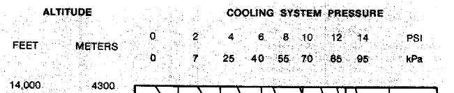
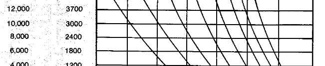
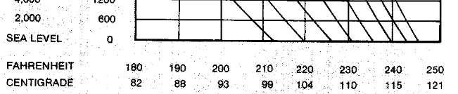

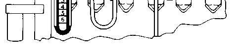
TESTINGTHETEMPERATUREGAUGE:Rememberthatboilingpointtemperatureand pressuregohand-in-handandneitheronecanbetestedlogicallywithoutconsideringtheother.For example,theeffectofpressurizationandaltitudeontheboilingpointofwaterisshowninthechart.
Ifoverheatingandlossofcoolantisaproblem,apressurelossinthesystemcouldbethecause.Ifan overheatingconditionisindicatedonthetemperaturegaugeandlossofcoolantisnotevident,check theaccuracyofthetemperaturegauge.Makethischeckbyinstallingathermometerwithasuitable bushingintothecylinderhead.

CHECKINGCOOLANTTEMPERATUREWITHTHERMOMETER
UseCAUTIONwhenworkingaroundmovingpartswiththeenginerunning.
Starttheengine.Partiallycovertheradiatortoreduceairflowandcooling.Thereadingonthe instrumentpanelgaugeshouldagreewiththereadingonthethermometer.
Thecoolingsystemisdesignedtoworkunderapressureof4to7psi(25to50kPa)toallowahigh heattransferforsizeofradiatorandfancombination.Inapressurizedsystem,aleakingradiatorcap allowslossofpressureandcoolant.Forasimplecheckofcoolingsystempressure,installapressure gaugeintheradiatortoptankandpressurizethesystem.Dothisbyeitherusinganairvalveand externalairsupply,handpump,orbyoperatingthemachineuntilthecoolantreachesoperating temperature.Systempressureshouldrisetoapproximately7psi(50kPa),andanyadditionalpressure shouldforceairpastthereliefvalvethroughtheoverflowopening.Donotallowpressuretoexceed 10psi(70kPa).
Thesystemshouldholdaminimumpressureofapproximately7psi(50kPa),andpressuremust remainconstantwiththeairsupplyshutoffortheenginerunningataconstanttemperature.
Ifthepressureisn'tmaintained,overflowlosscanoccurascoolingsystemtemperaturerises.Donot removethecapwhilethesystemisatoperatingtemperature.Checkcoolantlevelonlywhencold.
Ifthesystemdoesnotholdpressure,findtheleak.
Carefullyinspecttheradiatorcap,seals,sealingsurfacesandthetoptankfillernecksurfacefor damage.

WATERTEMPERATUREREGULATOR:Theopeningtemperatureoftheregulator(benchtest inatmosphericpressure)shouldbe165±1°F(74±1°C).Theregulatorshouldbefullyopenat approximately180°F(85°C).
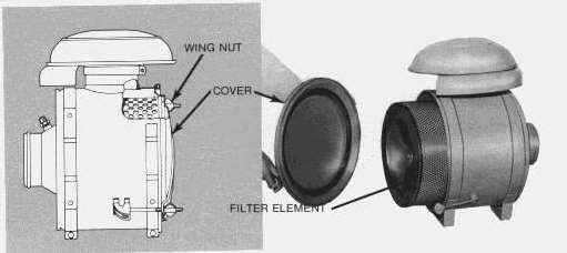
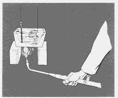
1.Removetheregulatorsfromthehousing.
2.Submergeeachregulatorandathermometerinapanofwaterasshown.
3.Applyheattothepanandstirthewatertomaintainuniformity.
4.Observetheopeningtemperatureofeachregulator.
WATERTEMPERATUREREGULATORREMOVAL
Ifeitherregulatordoesnotoperatecorrectlyinstallanewregulator.
COOLINGSYSTEMHOSES:Inspectallcoolanthosesannuallyandreplaceiftheyshowsignsof crackingorleaking.Periodicallyreplaceallradiatorandheaterhoses,asitismanytimesdifficultto determinetheconditionofawaterhosebyvisualinspectionandfeel.Coolanthosesareexpendable ite-sandperiodicrep,acementisconsideredgoodmaintenancepractice.
Incompleteorimproperfillingisamajorcauseof airinthecoolingsystem.Also,leaksinvariouscomponentssuchastheaftercooler,andhosesallow airtoenterthecoolingsystem,especiallyontheinletsideofthewaterpump.
Airinthesystemproducesfoamingoraerationandaffectswaterpumpperformance.Theairbubbles insulatevariouspartsoftheenginefromthecoolant,andhotspotsform.Astheairbubblescirculate orbreakup,coolantcontactsthehotsurfaces,creatingsteam.Thesteampocketshavebasicallythe sameeffectasairbubbles,acceleratingtheformationofmoresteam.Consequently,coolant dischargesthroughtheoverflow.
Exhaustgasleakageintothesystemcausessimilarconditions.Exhaustgascanenterthroughinternal cracksordefectivecylinderheadgaskets.
Mostofthecausescanbecheckedbyavisualinspection,whileothersrequiredisassemblyora simpletest.
Airinthecoolingsystemisonecauseofoverheatingwhichcanbelocatedbyasimpletestknownas the"bottletest".Theequipmentrequiredtoperformsuchatestconsistsofa1pint(1/2litre)bottle,a bucketofwater,andalengthofhosewithaninsidediameterlargeenoughtofitovertheendofthe radiatoroverflowpipe.
TOTEST:Fillthecoolingsystemtoproperlevel.Wireopenthereliefvalveintheradiatorcap. Installtheradiatorcapandtighten.Assembletherubberhoseovertheendoftheoverflowpipe.
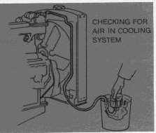
Starttheengineandoperateitathighidlespeedforatleastfiveminutesaftertheenginereaches operatingtemperature.Blockoffpartoftheairflowthroughtheradiatortomaintainoperating temperature.Afterthetemperaturehasstabilizedandallexpansionairhasventedout,placetheloose endofthehoseinthewaterfilledbottlewhichisinvertedinthebucketofwater.Ifittakeslessthana minutetodisplacethewaterinthepintbottle,leakageintothecoolingsystemisexcessive.
Looseprecombustionchambers,faultyprecombustionchamberseals,aloosecylinderhead,ora damagedheadgasketarepossiblecausesofairinthecoolingsystem.Inanycase,thecauseshouldbe correctedimmediately.
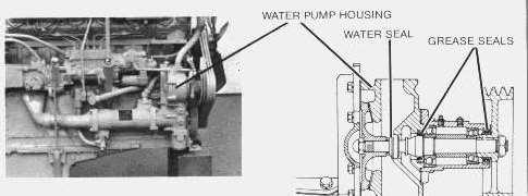
WATERPUMP:Thewaterpumpcirculatesthecoolantthroughtheaftercoolerandoilcooler,the cylinderblock,cylinderhead,andradiator.Poorcoolantcirculationcausesoverheating.Abadly corrodedorwornwaterpumpimpeller,orevenalooseimpeller,reducescirculationandefficiency.
Every100,000miles(160000km)inspectthewaterpumpandrebuildasnecessary,orinstalla rebuiltpumptoreducedowntimetoaminimum.Yourauthorizeddealerisfamiliarwithworn replacementlimitsandwithdisassemblyandassemblyprocedures.
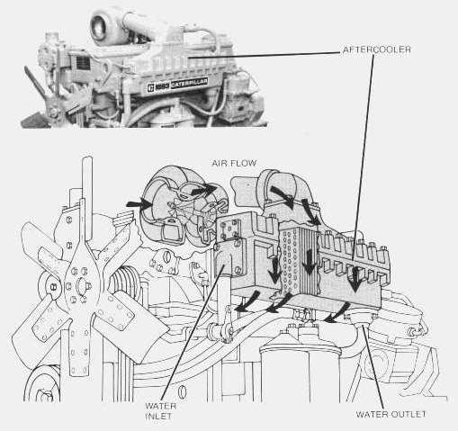
AFTERCOOLER:Theaftercoolerisasimpledeviceresemblingasmallradiatorcore.Waterfrom theenginepassesthroughthecoretubes.Engineinletair,warmedbytheturbochargercompressoris directedthroughthecoreandaroundthetubes.Sincethetemperatureofthewaterislowerthanthe air,theairiscooledasitleavestheaftercoolerandbecomesmoredenseasitenterstheintake manifold.Thismeansmoreair(oxygen)isavailableforcombustion,resultinginmorefuelbeing burnedandmorepowerproduced.
Onedegreeincreaseininletairtemperatureincreasesexhausttemperatureapproximatelythree degrees.Restrictionstoeithercoolantorairflowreduceaftercoolerefficiencyandseverelyaffectthe engineandcoolingsystem.
Every300,000miles(480000km)orwhenengineisbeingrebuilt,removetheaftercoolerandclean core,waterandairpassages.
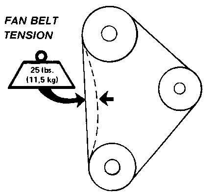
FANBELTS:Examinethedrivebeltsannuallyforwearandreplaceiftheyshowsignsofwear. Looseorwornpulleygroovescausebeltslippageandlowfanspeed.Iffanbeltsaretooloose,they vibrateenoughtocauseunnecessarywearonthebeltsandpulleysandpossiblyslipenoughtocause overheating.
Ifonebeltinasetrequiresreplacement,alwaysinstallanewmatchedsetofbelts-neverreplacejust thewornbelt.Ifonlythewornbeltisreplaced,thenewbeltwillcarryalltheload-asitwillnotbe stretchedasmuchastheolderbelts-andallthebeltswillfailinrapidsuccession.
TueNov2601:08:26UTC+05302024
Product:TRUCKENGINE
Model:1693TRUCKENGINE65B
Configuration:1693DIESELTRUCKENGINE65B02918-11050
1693TRUCKENGINE
MediaNumber-SEBU5433-01PublicationDate-01/10/1977DateUpdated-11/10/2001
ElectricalSystem
SMCS-1000;1250;1450;1453;1456;1900
Thefollowingtopicsdescribecareandmaintenanceoftheelectricalsystemcomponents.These componentsfunctioningtogetherproducetheenergyneededforoperatingtheelectricalequipmenton thetruckandeachisdependentupontheothersforsatisfactoryoperation.Intheeventoffailureor improperoperation,itisessentialtochecktheentireelectricalsystemasadefectinonecomponent cancausedamagetoanother.
Manyelectricalsystemproblemscanbetracedtolooseorcorrodedconnections.Keepconnections tightandmakesurethewiringinsulationisinsatisfactorycondition.Mostoftheelectricalsystem testingcanbeperformedonthevehicle.Itshouldberemembered,ifamalfunctionisfoundon vehicletest,thecomponentmustberemovedforfurthertesting,repairorreplacement.
NOTE:SomeinstallationsmayhaveelectricalcomponentsnotfurnishedbyCaterpillar.Consultthe vehiclemanufacturer'smanualformaintenanceprocedures.
Every10,000miles(160000km)checktheelectrolytelevelofeachcellandthegeneralconditionof thebattery.Maintaintheelectrolyteleveltothebaseofeachventwell.Themake-upwatermustbe oneofthefollowing(inorderofpreference):
1.Distilledwater.
2.Odorless,tastelessdrinkingwater.
3.Ironfreewater.
4.Anyavailablewater.
CLEANINGBATTERY:Mixaweaksolutionofbakingsodaandwater.Applythesolutionwitha softbristlebrush.Becarefulnottogetcleaningsolutionintothebattery.
Thoroughlyrinsethebatteryandbatterytraywithcleanwater.Applygreasetothebatterycable clampsandterminalsandtoallthreads.
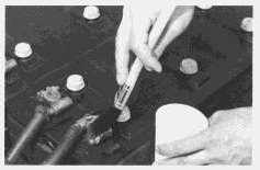
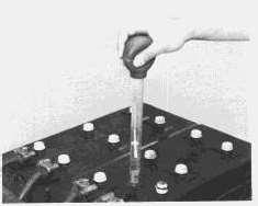
Thegeneralconditionofabatterycanbe determinedbymeasuringthespecificgravityoftheelectrolytesolutionandadjustingthereadingto 80°F(27°C).Iftheelectrolytelevelistoolowtoallowtakingahydrometerreading,addmake-up watertothecorrectlevelandthenchargethebattery2to4hoursbeforetakingareading.
1.Insertthehydrometerintoacell.Fillthehydrometerbarrelwhileholdingitvertically.Thefloat mustnotdragonthewallofthebarrel.
2.Readthehydrometer:
1.250orabove-fullychargedbatterycell
1.250-1.225-fulltohalfchargedbatterycell
1.225-1.150-halftolowchargedbatterycell
Below1.150-deadcell
1.000-water
3.Testeachcellinthesamemanner.
4.Ifthereismorethan.050(50gravitypoints)variationbetweenthehighestandlowestreading,the batteryshouldbereplaced.
5.Adjustthereadingsto80°F(27°C).
a.Forevery10°F(5.5°C)theelectrolytetemperatureisabove80°F(27°C),add.004(4gravity points)tothespecificgravityreadings.
b.Forevery10°F(5.5°C)theelectrolytetemperatureisbelow80°F(27°C),subtract.004(4gravity points)fromthespecificgravityreading.
Thecorrectedreadingisofmostimportanceduringcoldweatherwhenthehydrometerreadingis alwayscorrectedtoalowerspecificgravityreading.Alowreadingsignifiesthebatteryhasless availablepowertocranktheengineandthatboosterbatteriesmayberequired.
Aloadtestshouldbemadeonabatterythatdischargesvery rapidlywheninuse.Todothisapplyaresistanceofthreetimestheampere/hourratingofthebattery acrossthebatterymainterminals.Allowtheresistancetodischargethebatteryfor15secondsand immediatelytestthebatteryvoltage.A6voltbatteryingoodconditionwilltest4.5volts;a12volt batteryingoodconditionwilltest9voltsanda24voltbatterywilltest18volts.
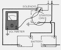
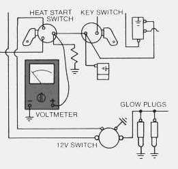
UseaD.C.voltmetertolocatestartingsystemcomponentswhichdonotfunction.
TurnthekeyswitchON.TurntheHEAT-STARTswitchtotheSTARTposition.Startingmotor solenoidoperationisaudibleasthestartermotorpinionengageswiththeringgearontheengine flywheel.Thesolenoidoperationshouldalsoclosetheelectriccircuittothestartingmotor.Attach onevoltmeterleadtothesolenoidterminalthatisconnectedtothestartingmotor.Groundtheother lead.TurntheHEAT-STARTswitchtoSTARTandobservethevoltmeter.Abatteryvoltagereading indicatesthemalfunctionisinthestartingmotor.Itmustberemovedforfurthertesting.Novoltmeter readingindicatesthatthesolenoidcontactsdonotclose.Thesolenoidmustberepairedorthestarter pinionclearanceshouldbeadjustedto.36in.(9,14mm).SeetopicPINIONCLEARANCE ADJUSTMENT.
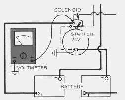
Astartingmotorsolenoidthatwillnotoperatemaynotbereceivingbatterycurrent.Attachonelead ofthevoltmetertothesolenoidbatterycableconnection.Groundtheotherlead.Novoltmeterreading indicatesafaultycircuitfromthebattery.Avoltmeterreadingindicatesfurthertestingisnecessary.
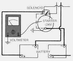
Continuethetestbyattachingonevoltmeterleadtothestartingmotorsolenoidsmallwireterminal andtheotherleadtoground.ObservethevoltmeterandturntheHEAT-STARTswitchtoSTART.A voltmeterreadingindicatesthatthemalfunctionisinthesolenoid.Novoltmeterreadingindicatesthat eithertheseries-parallelswitchisthefaultortheHEAT-STARTswitchdoesnotclosewhenturnedto theSTARTposition.
AttachoneleadofthevoltmetertotheHEAT-STARTswitchbatterywireterminalandgroundthe otherlead.Avoltmeterreadingindicatesadefectiveswitch.Novoltmeterreadingindicatesfurther testingoftheseries-parallelswitchisnecessary.
Astartingmotorthatoperatestooslowcanbeoverloadedbyexcessivemechanicalfrictionwithinthe enginebeingstarted.Slowstartingmotoroperationcanalsobecausedbyshorts,looseconnections and/orexcessivedirtwithinthemotor.
Wheneverthesolenoidisinstalled,thepinionclearance shouldbeadjusted.Theadjustmentshouldbemadewiththestartingmotorremoved.
Benchtestandadjustthepinionclearanceatinstallationofsolenoidasfollows:
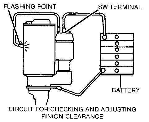
1.InstallthesolenoidwithoutconnectorfromtheMOTORterminalonsolenoidtothemotor.
2.Connectabattery,ofthesamevoltageasthesolenoid,totheterminalmarkedSW.
3.Connecttheothersideofbatterytogroundterminalortosolenoidframe.
4.MOMENTARILYflashajumperwirefromthesolenoidterminalmarkedMOTORtotheframeor groundterminal.Thepinionwillshiftintocrankingpositionandwillremainthereuntilthebatteryis disconnected.
5.Pushpiniontowardscommutatorendtoeliminatefreemovement.
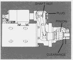
6.Pinionclearanceshouldbe.36in.(9,14mm).
7.Adjustclearancebyremovingplugandturningshaftnut.
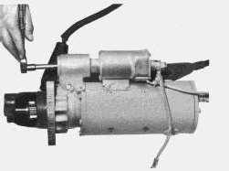
Approximatelyevery200,000miles,thestartershouldberemovedsothatitmaybecompletely disassembled,washedandhaveallpartsreplacedthatshowevidenceofbeingunsatisfactoryfor reasonofwear.Donotuseadegreaserorhightemperaturecleaningmethodwhencleaningpartsof thestarter.
Noperiodicserviceisindicatedfortheelectricstarterbrushesbetweengeneralreconditioning periods.Thebrushesshouldonlybeinspectedafterremovalofthestarterfromtheengineand removalofthecommutatorendbearingframe.Theelectricstartercommutatorendanddriveend bearingsareequippedwithwicksforlubricationpurposes.Thewicksshouldbesaturatedwithoil whenevertheelectricstarterisremovedordisassembled.
Itissuggestedthatcleaningandreconditioningbeentrustedtoyourauthorizeddealer.
Glowplugscanbecheckedwithanammeter.Disconnectthewirelead fromtheglowplugterminalontheHEAT-STARTswitch.Installanammeter,inseries,betweenthe disconnectedleadandtheterminalontheswitch.ObservetheammeterwiththeHEAT-START switchturnedtotheHEATposition.Each12voltglowplugdrawsapproximately12.5amperes. Glowplugsinearlierenginesdrawapproximately10amperes.Theamperedrawofoneglowplug multipliedbythenumberofenginecylinderswillbethetotalamperedrawoftheglowplugsinthe engine.Alowreadingisanindicationofoneormoredefectiveglowplugs.Disconnectoneglowplug leadatatimeandobservetheammeterwiththeswitchturnedtoHEAT.Thedisconnectedglowplug thatdoesnotchangetheammeterreadingisthedefectiveglowplug.
This is the sample of the manual if you need complete manual Click Here to download