DOWNLOAD LINK
For some reason if link does not work download this pdf and then click
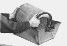
Filter elements can be cleaned several times before replacing; however, close inspection of the element should be made when reinstalling a cleaned element.
The ends of a filter element will be damaged by bumping or tapping. Bent and/or dented ends cannot seal properly and may allow unfiltered air to enter the engine cylinders and cause premature engine wear.
Clean the filter element using one of the following methods:
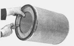
CLEANING WITH PRESSURE AIR: Using clean, dry air, at a pressure not to exceed 30 psi (205 kPa), proceed as follows:
Hold the air nozzle at least one inch from the element and direct air at an angle against the inside (engine side) of the element to loosen any imbedded dirt. Best results can be obtained by moving the air hose so that air is directed at an angle along the complete length of each pleat.
Blow off loose dirt by directing air against the outside of the element. Repeat this procedure until the element is clean. Make certain that no dirt is inside the element.
CLEANING ELEMENT WITH AIR
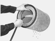
CLEANING WITH WATER: Using clean water, at a pressure not to exceed 40 psi (280 kPa), proceed as follows.
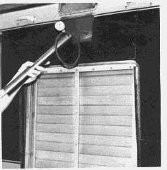
Direct water at an angle against the inside (engine side) of the element to loosen any imbedded dirt. Best results can be obtained by using a water hose without a nozzle and moving it so that water is directed at an angle along the complete length of each pleat. Wash off loose dirt by directing water against the outside of the element. Repeat this procedure until the element is clean. Make certain that no dirt is on the engine side of the element, and thoroughly dry the element before installing it.
CLEANING ELEMENT WITH WATER
CLEANING WITH DETERGENT: Some oily and/or sooty deposits can be removed by washing the element in a solution of warm water and a good household non-sudsing detergent. Rinse with clean water and thoroughly dry the element before installing it.
WASHING ELEMENT WITH DETERGENT
INSPECTING ELEMENT:
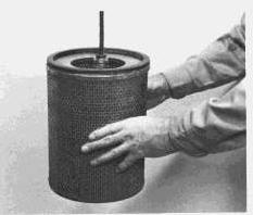
1. Hold a lighted electric bulb inside the dried element and carefully inspect the element for tiny, pinpoints of light. Any light showing indicates a pleat has ruptured and will tear with further use. Discard the element.
2. Wrap usable elements in sealed plastic bags.
3. Store the wrapped element in a dry, clean place.
INSPECTING ELEMENT
When equipped with oil bath type air cleaners, accumulation of dirt and/or oil in the air cleaner outlet pipe is an indication the air cleaner is not being serviced or functioning properly. Refer to manufacturer's recommendations for servicing.
Valve Lash Setting
Make valve lash adjustment every 100,000 miles (160 000 km) with engine stopped. TDC of the No. 1 piston on the compression stroke is the reference point. No. 1 piston is at TDC compression stroke when the No. 1 valves are closed.
TO ADJUST VALVE LASH:
Remove the valve cover. The four valves at the front of the engine are the inlet and exhaust valves for No. 1 cylinder.
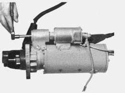
1. Rotate the flywheel counterclockwise (as viewed from the flywheel end of the engine) until timing bolt can be installed in flywheel.
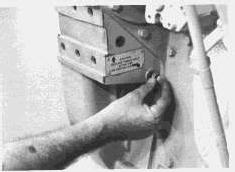
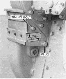
2. Install the timing bolt through the opening for the plug and into the threaded hole in flywheel. All valves for No. 1 cylinder should now be closed.
TIMING BOLT INSTALLATION
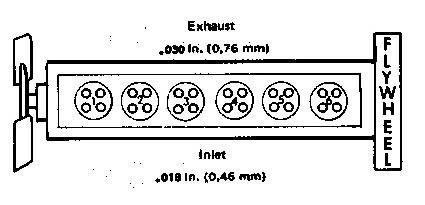
3. With No. 1 piston at TDC compression stroke, adjust lash on 1, 3 and 5 exhaust and 1, 2 and 4 inlet valves.
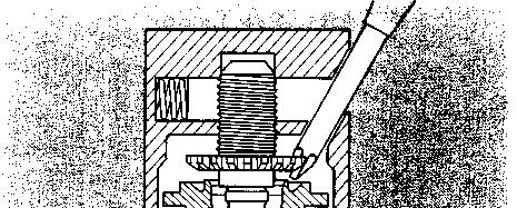
4. Turn cam follower on valve being adjusted until the slanted hole in the follower faces the center of the engine.
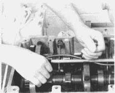
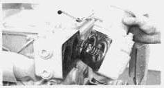
5. Insert a Phillips screwdriver in the slanted hole and turn screwdriver clockwise to increase valve lash or counterclockwise to decrease the valve lash. With a clearance gauge, measure valve lash between the cam follower and the cam. Correct valve lash is .030" (0.76 mm) for exhaust valves and .018" (0.46 mm) for inlet valves.
VALVE ADJUSTMENT
6. Remove the timing bolt and turn the crankshaft 360° counterclockwise. Align flywheel timing bolt.
7. Adjust lash on 2, 4 and 6 exhaust and 3, 5 and 6 inlet valves.
8. After adjusting, install the timing bolt and the plug back in their original locations.
TIMING BOLT STORAGE LOCATION
Compression Check
The following procedure provides a check of the sealing ability of the individual valves and piston rings without removing the cylinder head:
1. Remove the fuel injection nozzle from the suspected cylinder, leaving the precombustion chamber in place.
2. Adapt an air hose to the precombustion chamber. This can be done with either a threaded fitting or by holding a rubber adapter in place.
3. Rotate the crankshaft until the piston in the suspected cylinder is at top center (TC) on the compression stroke. In this position the valves of this cylinder are closed.
NOTICE
Lock engine to prevent rotating.
4. Force air into the cylinder and then check for escaping air. Air escaping from the exhaust opening indicates exhaust valve leakage. Air escaping from the air cleaner inlet indicates inlet valve leakage. If air escapes from the crankcase breather during this test, the piston, rings and/or liner can be at fault.
It may be necessary to remove inlet and outlet connections on both sides of the turbocharger to notice leakage from inlet and/or exhaust valves.
An alternate and more accurate method of checking compression can be made with the use of an air regulator valve, gauges and an adapter group. Authorized dealers have the necessary equipment and can perform this service for you or supply you with the necessary instructions.
Crankcase Pressure
Excessive crankcase pressure can be a result of combustion gas leaking past broken or damaged pistons, worn cylinder liner walls and/or piston rings. This condition will usually be accompanied by irregular engine operation and excess fumes from crankcase breather opening. This pressure can cause the breather element to become restricted in an unusually short time. In addition, it can cause engine oil to leak past gaskets and seals that would function properly under normal conditions.
Turbocharger
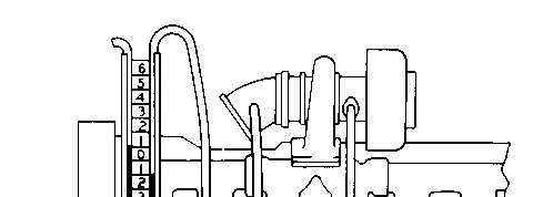
Every 200,000 miles (320 000 km) of if any unusual sound or vibration in the turbocharger is noticed, a quick check of bearing condition can be made without disassembling the turbocharger. This can be done by removing the piping from the turbocharger and inspecting the compressor impeller, turbine wheel and compressor cover. Rotate the compressor and turbine wheel assembly by hand and observe by feeling excess end play and radial clearance. The rotating assembly should rotate freely with no rubbing or binding. If there is any indication of the impeller rubbing the compressor cover or the turbine wheel rubbing the turbine housing, recondition the turbocharger or replace with a new or rebuilt one.
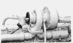
End clearance is best checked with a dial indicator. Attach a dial indicator with the indicator point on the end of the shaft. Move the shaft from end to end making note of the total indicator reading.
End play should be between .004 in. (0,076 mm) and .009 in. (0,203 mm). If end play exceeds .009 in. (0,203 mm) rebuild or replace the turbocharger. End clearance less than .004 in. (0,076 mm) could indicate carbon build-up on the turbine wheel and should be disassembled for cleaning and inspection.
CHECKING TURBOCHARGER ROTATING ASSEMBLY END PLAY
A more reliable check of bearing condition can be made only when the turbocharger is disassembled and the bearings, shaft journal and housing bore diameters can actually be measured. This service is available from an authorized dealer.
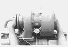
Radial clearance can also be checked with a dial indicator. Remove the oil return line from the turbocharger. Attach a dial indicator with an extension indicator point long enough to contact the shaft through the oil return hole. Make sure the contact point is centered on the shaft (highest indicator reading). Raise both ends of the shaft all the way then push down in the opposite direction. Total movement of the indicator should be between .005 in. (0,13 mm) and .009 in. (0,23 mm). If radial clearance exceeds .009 in. (0,23 mm) or minimum clearance is under .005 in. (0,13 mm), the turbocharger should be disassembled and the bearings checked.
NOTE: Care must be taken not to cock the shaft or a false reading will be obtained.
CHECKING TURBOCHARGER RADIAL CLEARANCE
If a turbocharger fails, try to determine cause of failure and eliminate before installing a rebuilt or new turbocharger. When installing a new or rebuilt turbocharger always perform the following steps.
A. Inspect the air induction and exhaust system for the presence of foreign particles which could result in repeat failure.
B. Change the air cleaner element.
C. Change the oil filters.
D. Drain and refill the engine crankcase.
E. Pre-lubricate the replacement turbocharger by filling the center housing with oil.
Copyright 1993 - 2024 Caterpillar Inc. All Rights Reserved.
Network For SIS Licensees. Tue Nov 26 01:08:46 UTC+0530 2024
Product: TRUCK ENGINE
Model: 1693 TRUCK ENGINE 65B
Configuration: 1693 DIESEL TRUCK ENGINE 65B02918-11050
Operation and Maintenance Manual
1693 TRUCK ENGINE
Cooling System
SMCS - 1000; 1250; 1450; 1453; 1456; 1900
The engine should be equipped with a radiator which has a sealed pressure radiator cap for pressurizing the cooling system. Pressurizing the cooling system serves two purposes. First, it permits safe operation at coolant temperature higher than the normal boiling point; thereby, providing a margin of cooling the those intermittent peak loads. Secondly, it helps prevent cavitation in the water pump and reduces the possibility of air or steam pockets forming in the coolant passages.
COOLANT LEVEL: Check the engine coolant level daily (with engine stopped). Carefully release cooling system pressure before checking. Fill to the proper level with permanent-type antifreeze and water. Use water which is free as possible from scale forming minerals, (not softened water).
INHIBITOR CONTAINS ALKALI.
Avoid contact with eyes. Avoid prolonged or repeated contact with skin. Do not take internally. In case of contact, immediately wash skin with soap and water. For eyes, flush with large amounts of water for at least 15 minutes. CALL PHYSICIAN. KEEP OUT OF REACH OF CHILDREN.
Before placing the engine in operation, make sure a 3% concentration of Caterpillar Corrosion Inhibitor or equivalent has been added to the cooling system.
NOTICE
Do not use with Dowtherm 209.
Every 3 months, 500 service hours or 25,000 miles (40,000 km) whichever occurs first, add corrosion inhibitor to maintain the recommended 3% concentration.
Refer to the application chart on the container for initial fill and maintenance fill amounts.
NOTICE
Add coolant slowly to a hot engine to prevent possible cracking or distorting the cylinder head.
If a loss of coolant is noticeable, check for leaks in the system. After filling the system, start the engine and recheck the coolant level after normal operating temperature is reached. Running the engine at operating temperature will permit the temperature regulator to open and allow the coolant to circulate through the entire system and purge air from the engine.
CLEANING THE RADIATOR (External): Every 10,000 miles clean dirt and trash from between the tubes of the radiator which may cause excessively high operating temperature. Wash, brush or blow the dirt out with whichever method is available and most effective.
CLEANING THE COOLING SYSTEM (Internal): Clean the cooling system periodically. Mineral deposits can cause serious engine damage by retarding the transfer of heat to the coolant. A deposit of lime 1/32inch thick insulates the same amount as 2 inches of steel, reducing the heat transfer substantially. Loose scale and sediment deposited in the cooling system will reduce circulation, resulting in possible engine damage. To clean, stop the engine when it is at normal operating temperature and drain as quickly as possible. Flush thoroughly, then fill with a solution of one pound of Oxalic Acid or Sodium Bisulfate per five gallons of water. Run the engine at operating temperature one-half to one hour, then drain and flush until water is clear. Fill with a solution of one-half pound of Sal Soda per ten gallons of water and run the engine ten minutes. Drain, flush and fill with water, adding coolant inhibitor and the desired amount of anti-freeze.
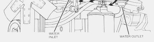
DRAINING: The cooling system is drained by removing the radiator cap, opening the valve in the bottom of the radiator, removing the drain plugs from the water pump and from the left side of the diesel engine block.
FILLING THE COOLING SYSTEM: When filling a cooling system it is essential for the system to be filled completely and air pockets eliminated. Air trapped in the system can cause loss of water pump priming resulting in coolant flow stoppage and possible engine damage.
Proper filling procedure is necessary to assure the cooling system is completely filled. Follow the four step recommended procedure.
1. Fill the radiator without interrupting flow of fill water.
2. Start the engine.
3. Complete filling with the engine running at low idle. It is important this filling be completed as quickly as possible after engine startup.
4. Before installing the radiator cap allow the engine to run at low idle for several minutes then add coolant as necessary. Warm coolant circulating in the top tank is a good indication the system is full. Make sure the system is bled of air and refilled with coolant after a short period of operation. Normally the air will purge out the air vent line leading to the top tank of the radiator.
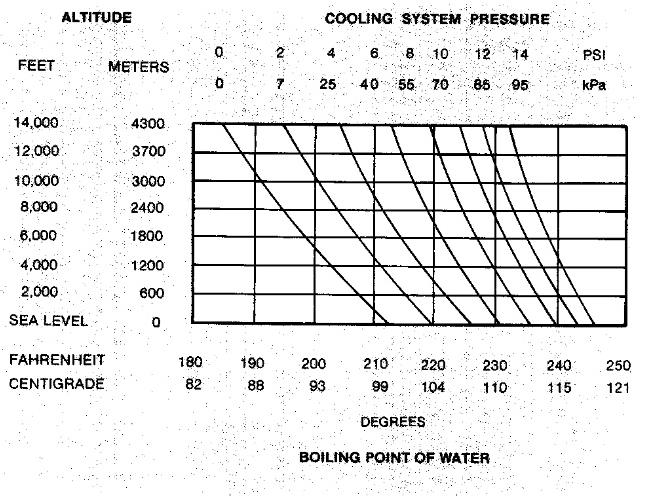
TESTING THE TEMPERATURE GAUGE: Remember that boiling point temperature and pressure go hand-in-hand and neither one can be tested logically without considering the other. For example, the effect of pressurization and altitude on the boiling point of water is shown in the chart.
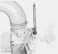
If overheating and loss of coolant is a problem, a pressure loss in the system could be the cause. If an overheating condition is indicated on the temperature gauge and loss of coolant is not evident, check the accuracy of the temperature gauge. Make this check by installing a thermometer with a suitable bushing into the cylinder head.
CHECKING COOLANT TEMPERATURE WITH THERMOMETER
Use CAUTION when working around moving parts with the engine running.
Start the engine. Partially cover the radiator to reduce air flow and cooling. The reading on the instrument panel gauge should agree with the reading on the thermometer.
Testing Cooling System Pressure
The cooling system is designed to work under a pressure of 4 to 7 psi (25 to 50 kPa) to allow a high heat transfer for size of radiator and fan combination. In a pressurized system, a leaking radiator cap allows loss of pressure and coolant. For a simple check of cooling system pressure, install a pressure gauge in the radiator top tank and pressurize the system. Do this by either using an air valve and external air supply, hand pump, or by operating the machine until the coolant reaches operating temperature. System pressure should rise to approximately 7 psi (50 kPa), and any additional pressure should force air past the relief valve through the overflow opening. Do not allow pressure to exceed 10 psi (70 kPa).
The system should hold a minimum pressure of approximately 7 psi (50 kPa), and pressure must remain constant with the air supply shut off or the engine running at a constant temperature.
PRESSURIZING THE SYSTEM
If the pressure isn't maintained, overflow loss can occur as cooling system temperature rises. Do not remove the cap while the system is at operating temperature. Check coolant level only when cold.
If the system does not hold pressure, find the leak.
Carefully inspect the radiator cap, seals, sealing surfaces and the top tank filler neck surface for damage.
WATER TEMPERATURE REGULATOR: The opening temperature of the regulator (bench test in atmospheric pressure) should be 165 ± 1°F (74 ± 1°C). The regulator should be fully open at approximately 180°F (85°C).
1. Remove the regulators from the housing.
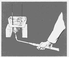
2. Submerge each regulator and a thermometer in a pan of water as shown.
3. Apply heat to the pan and stir the water to maintain uniformity.
4. Observe the opening temperature of each regulator. WATER TEMPERATURE REGULATOR REMOVAL
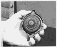
RADIATOR CAP
If either regulator does not operate correctly install a new regulator.
COOLING SYSTEM HOSES: Inspect all coolant hoses annually and replace if they show signs of cracking or leaking. Periodically replace all radiator and heater hoses, as it is many times difficult to determine the condition of a water hose by visual inspection and feel. Coolant hoses are expendable ite-s and periodic rep,acement is considered good maintenance practice.
AIR,
GASES AND
STEAM IN THE SYSTEM: Incomplete or improper filling is a major cause of air in the cooling system. Also, leaks in various components such as the aftercooler, and hoses allow air to enter the cooling system, especially on the inlet side of the water pump.
Air in the system produces foaming or aeration and affects water pump performance. The air bubbles insulate various parts of the engine from the coolant, and hot spots form. As the air bubbles circulate or break up, coolant contacts the hot surfaces, creating steam. The steam pockets have basically the same effect as air bubbles, accelerating the formation of more steam. Consequently, coolant discharges through the overflow.
Exhaust gas leakage into the system causes similar conditions. Exhaust gas can enter through internal cracks or defective cylinder head gaskets.
Most of the causes can be checked by a visual inspection, while others require disassembly or a simple test.
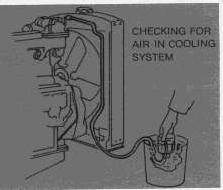
Air in the cooling system is one cause of overheating which can be located by a simple test known as the "bottle test". The equipment required to perform such a test consists of a 1 pint (1/2 litre) bottle, a bucket of water, and a length of hose with an inside diameter large enough to fit over the end of the radiator overflow pipe.
TO TEST: Fill the cooling system to proper level. Wire open the relief valve in the radiator cap. Install the radiator cap and tighten. Assemble the rubber hose over the end of the overflow pipe.
Start the engine and operate it at high idle speed for at least five minutes after the engine reaches operating temperature. Block off part of the air flow through the radiator to maintain operating temperature. After the temperature has stabilized and all expansion air has vented out, place the loose end of the hose in the water filled bottle which is inverted in the bucket of water. If it takes less than a minute to displace the water in the pint bottle, leakage into the cooling system is excessive.
Loose precombustion chambers, faulty precombustion chamber seals, a loose cylinder head, or a damaged head gasket are possible causes of air in the cooling system. In any case, the cause should be corrected immediately.
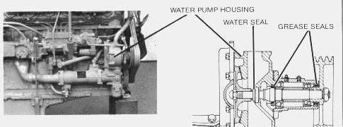
WATER PUMP: The water pump circulates the coolant through the aftercooler and oil cooler, the cylinder block, cylinder head, and radiator. Poor coolant circulation causes overheating. A badly corroded or worn water pump impeller, or even a loose impeller, reduces circulation and efficiency.
Every 100,000 miles (160 000 km) inspect the water pump and rebuild as necessary, or install a rebuilt pump to reduce down time to a minimum. Your authorized dealer is familiar with worn replacement limits and with disassembly and assembly procedures.
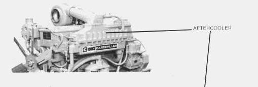
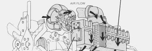
AFTERCOOLER: The aftercooler is a simple device resembling a small radiator core. Water from the engine passes through the core tubes. Engine inlet air, warmed by the turbocharger compressor is directed through the core and around the tubes. Since the temperature of the water is lower than the air, the air is cooled as it leaves the aftercooler and becomes more dense as it enters the intake manifold. This means more air (oxygen) is available for combustion, resulting in more fuel being burned and more power produced.
One degree increase in inlet air temperature increases exhaust temperature approximately three degrees. Restrictions to either coolant or air flow reduce aftercooler efficiency and severely affect the engine and cooling system.
Every 300,000 miles (480 000 km) or when engine is being rebuilt, remove the aftercooler and clean core, water and air passages.
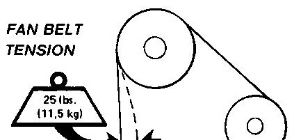
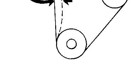
FAN BELTS: Examine the drive belts annually for wear and replace if they show signs of wear. Loose or worn pulley grooves cause belt slippage and low fan speed. If fan belts are too loose, they vibrate enough to cause unnecessary wear on the belts and pulleys and possibly slip enough to cause overheating.
If one belt in a set requires replacement, always install a new matched set of belts - never replace just the worn belt. If only the worn belt is replaced, the new belt will carry all the load - as it will not be stretched as much as the older belts - and all the belts will fail in rapid succession.
Tue Nov 26 01:08:26 UTC+0530 2024
Product: TRUCK ENGINE
Model: 1693 TRUCK ENGINE 65B
Configuration: 1693 DIESEL TRUCK ENGINE 65B02918-11050
Operation and Maintenance Manual
1693 TRUCK ENGINE
Electrical System
SMCS - 1000; 1250; 1450; 1453; 1456; 1900
The following topics describe care and maintenance of the electrical system components. These components functioning together produce the energy needed for operating the electrical equipment on the truck and each is dependent upon the others for satisfactory operation. In the event of failure or improper operation, it is essential to check the entire electrical system as a defect in one component can cause damage to another.
Many electrical system problems can be traced to loose or corroded connections. Keep connections tight and make sure the wiring insulation is in satisfactory condition. Most of the electrical system testing can be performed on the vehicle. It should be remembered, if a malfunction is found on vehicle test, the component must be removed for further testing, repair or replacement.
NOTE: Some installations may have electrical components not furnished by Caterpillar. Consult the vehicle manufacturer's manual for maintenance procedures.
Battery
Every 10,000 miles (160 000 km) check the electrolyte level of each cell and the general condition of the battery. Maintain the electrolyte level to the base of each vent well. The make-up water must be one of the following (in order of preference):
1. Distilled water.
2. Odorless, tasteless drinking water.
3. Iron free water.
4. Any available water.
Never add acid or electrolyte.
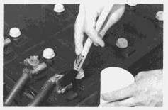
CLEANING BATTERY: Mix a weak solution of baking soda and water. Apply the solution with a soft bristle brush. Be careful not to get cleaning solution into the battery.
CLEANING BATTERY TERMINALS
Thoroughly rinse the battery and battery tray with clean water. Apply grease to the battery cable clamps and terminals and to all threads.
TESTING THE ELECTROLYTE SOLUTION:
The general condition of a battery can be determined by measuring the specific gravity of the electrolyte solution and adjusting the reading to 80°F (27°C). If the electrolyte level is too low to allow taking a hydrometer reading, add make-up water to the correct level and then charge the battery 2 to 4 hours before taking a reading.
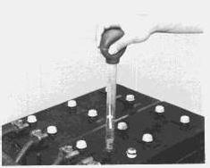
1. Insert the hydrometer into a cell. Fill the hydrometer barrel while holding it vertically. The float must not drag on the wall of the barrel.
2. Read the hydrometer:
1.250 or above - fully charged battery cell
1.250-1.225 - full to half charged battery cell
1.225-1.150 - half to low charged battery cell
Below 1.150 - dead cell
1.000 - water
3. Test each cell in the same manner.
4. If there is more than .050 (50 gravity points) variation between the highest and lowest reading, the battery should be replaced.
5. Adjust the readings to 80°F (27°C).
a. For every 10°F (5.5°C) the electrolyte temperature is above 80°F (27°C), add .004 (4 gravity points) to the specific gravity readings.
b. For every 10°F (5.5°C) the electrolyte temperature is below 80°F (27°C), subtract .004 (4 gravity points) from the specific gravity reading.
The corrected reading is of most importance during cold weather when the hydrometer reading is always corrected to a lower specific gravity reading. A low reading signifies the battery has less available power to crank the engine and that booster batteries may be required.
TESTING ELECTROLYTE SOLUTION
VOLTAGE TEST (AFTER LOAD): A load test should be made on a battery that discharges very rapidly when in use. To do this apply a resistance of three times the ampere/hour rating of the battery across the battery main terminals. Allow the resistance to discharge the battery for 15 seconds and immediately test the battery voltage. A 6 volt battery in good condition will test 4.5 volts; a 12 volt battery in good condition will test 9 volts and a 24 volt battery will test 18 volts.
Starting System
Use a D.C. voltmeter to locate starting system components which do not function.
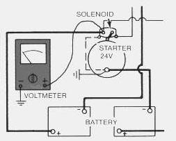
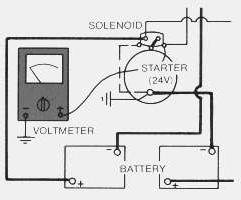
Turn the key switch ON. Turn the HEAT-START switch to the START position. Starting motor solenoid operation is audible as the starter motor pinion engages with the ring gear on the engine flywheel. The solenoid operation should also close the electric circuit to the starting motor. Attach one voltmeter lead to the solenoid terminal that is connected to the starting motor. Ground the other lead. Turn the HEAT-START switch to START and observe the voltmeter. A battery voltage reading indicates the malfunction is in the starting motor. It must be removed for further testing. No voltmeter reading indicates that the solenoid contacts do not close. The solenoid must be repaired or the starter pinion clearance should be adjusted to .36 in. (9,14 mm). See topic PINION CLEARANCE ADJUSTMENT.
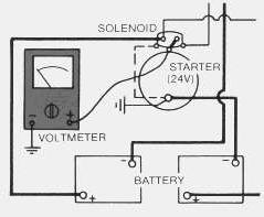
A starting motor solenoid that will not operate may not be receiving battery current. Attach one lead of the voltmeter to the solenoid battery cable connection. Ground the other lead. No voltmeter reading indicates a faulty circuit from the battery. A voltmeter reading indicates further testing is necessary.
Continue the test by attaching one voltmeter lead to the starting motor solenoid small wire terminal and the other lead to ground. Observe the voltmeter and turn the HEAT-START switch to START. A voltmeter reading indicates that the malfunction is in the solenoid. No voltmeter reading indicates that either the series-parallel switch is the fault or the HEAT-START switch does not close when turned to the START position.
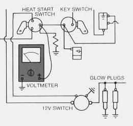
Attach one lead of the voltmeter to the HEAT-START switch battery wire terminal and ground the other lead. A voltmeter reading indicates a defective switch. No voltmeter reading indicates further testing of the series-parallel switch is necessary.
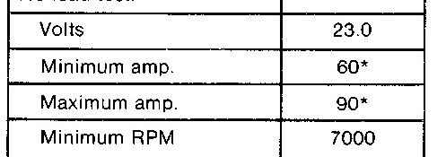
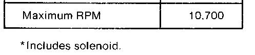
A starting motor that operates too slow can be overloaded by excessive mechanical friction within the engine being started. Slow starting motor operation can also be caused by shorts, loose connections and/or excessive dirt within the motor.
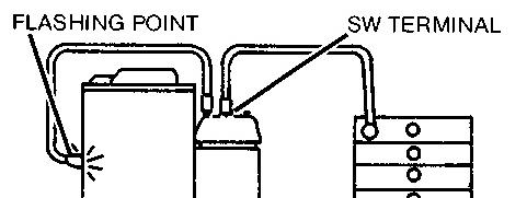
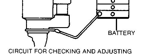
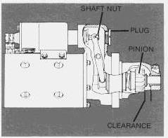
PINION CLEARANCE ADJUSTMENT: Whenever the solenoid is installed, the pinion clearance should be adjusted. The adjustment should be made with the starting motor removed.
Bench test and adjust the pinion clearance at installation of solenoid as follows:
1. Install the solenoid without connector from the MOTOR terminal on solenoid to the motor.
2. Connect a battery, of the same voltage as the solenoid, to the terminal marked SW.
3. Connect the other side of battery to ground terminal or to solenoid frame.
4. MOMENTARILY flash a jumper wire from the solenoid terminal marked MOTOR to the frame or ground terminal. The pinion will shift into cranking position and will remain there until the battery is disconnected.
5. Push pinion towards commutator end to eliminate free movement.
6. Pinion clearance should be .36 in. (9,14 mm).
7. Adjust clearance by removing plug and turning shaft nut.
General Reconditioning
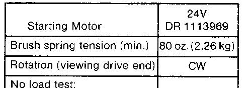
Approximately every 200,000 miles, the starter should be removed so that it may be completely disassembled, washed and have all parts replaced that show evidence of being unsatisfactory for reason of wear. Do not use a degreaser or high temperature cleaning method when cleaning parts of the starter.
No periodic service is indicated for the electric starter brushes between general reconditioning periods. The brushes should only be inspected after removal of the starter from the engine and removal of the commutator end bearing frame. The electric starter commutator end and drive end bearings are equipped with wicks for lubrication purposes. The wicks should be saturated with oil whenever the electric starter is removed or disassembled.
It is suggested that cleaning and reconditioning be entrusted to your authorized dealer.
Glow Plugs
TESTING GLOW PLUGS: Glow plugs can be checked with an ammeter. Disconnect the wire lead from the glow plug terminal on the HEAT-START switch. Install an ammeter, in series, between the disconnected lead and the terminal on the switch. Observe the ammeter with the HEAT-START switch turned to the HEAT position. Each 12 volt glow plug draws approximately 12.5 amperes. Glow plugs in earlier engines draw approximately 10 amperes. The ampere draw of one glow plug multiplied by the number of engine cylinders will be the total ampere draw of the glow plugs in the engine. A low reading is an indication of one or more defective glow plugs. Disconnect one glow plug lead at a time and observe the ammeter with the switch turned to HEAT. The disconnected glow plug that does not change the ammeter reading is the defective glow plug.