DOWNLOAD LINK
For some reason if link does not work download this pdf and then click
Product: MOTOR GRADER
Model: 150 MOTOR GRADER B56
Configuration: 150 AWD Motor Grader B5600001-UP (MACHINE) POWERED BY C9 Engine
Operation and Maintenance Manual
140M and 150 Motor Grader
Guards - Operator Protection
SMCS - 7000
There are different types of guards that are used to protect the operator. The machine and the machine application determine the type of guard that should be used.
A daily inspection of the guards is required in order to check for structures that are bent, cracked, or loose. Never operate a machine with a damaged structure.
The operator becomes exposed to a hazardous situation if the machine is used improperly or if poor operating techniques are used. This situation can occur even though a machine is equipped with an appropriate protective guard. Follow the established operating procedures that are recommended for your machine.
Rollover Protective Structure (ROPS), Falling Object
Protective Structure (FOPS) or Tip Over Protection Structure (TOPS)
The ROPS/FOPS Structure (if equipped) on your machine is specifically designed, tested and certified for that machine. Any alteration or any modification to the ROPS/FOPS Structure could weaken the structure. This places the operator into an unprotected environment. Modifications or attachments that cause the machine to exceed the weight that is stamped on the certification plate also place the operator into an unprotected environment. Excessive weight may inhibit the brake performance, the steering performance and the ROPS. The protection that is offered by the ROPS/FOPS Structure will be impaired if the ROPS/FOPS Structure has structural damage. Damage to the structure can be caused by an overturn, a falling object, a collision, etc.
Do not mount items (fire extinguishers, first aid kits, work lights, etc) by welding brackets to the ROPS/FOPS Structure or by drilling holes in the ROPS/FOPS Structure. Welding brackets or drilling holes in the ROPS/FOPS Structures can weaken the structures. Consult your Cat dealer for mounting guidelines.
The Tip Over Protection Structure (TOPS) is another type of guard that is used on mini hydraulic excavators. This structure protects the operator in the event of a tipover. The same guidelines for
i07746359
the inspection, the maintenance and the modification of the ROPS/FOPS Structure are required for the Tip Over Protection Structure.
Other Guards (If Equipped)
Protection from flying objects and/or falling objects is required for special applications. Logging applications and demolition applications are two examples that require special protection.
A front guard needs to be installed when a work tool that creates flying objects is used. Mesh front guards that are approved by Caterpillar or polycarbonate front guards that are approved by Caterpillar are available for machines with a cab or an open canopy. On machines that are equipped with cabs, the windows should also be closed. Safety glasses are recommended when flying hazards exist for machines with cabs and machines with open canopies.
If the work material extends above the cab, top guards and front guards should be used. Typical examples of this type of application are listed below:
• Demolition applications
• Rock quarries
• Forestry products
Additional guards may be required for specific applications or work tools. The Operation and Maintenance Manual for your machine or your work tool will provide specific requirements for the guards. Refer to Operation Maintenance manual, "Demolition" for additional information. Consult your Cat dealer for additional information.
Product: MOTOR GRADER
Model: 150 MOTOR GRADER B56
Configuration: 150 AWD Motor Grader B5600001-UP (MACHINE) POWERED BY C9 Engine
Operation
and Maintenance Manual
140M and 150 Motor Grader
Media Number -SEBU7881-31
Operator Station
SMCS - 7000
Any modifications to the inside of the operator station should not project into the operator space or into the space for the companion seat (if equipped). The addition of a radio, fire extinguisher, and other equipment must be installed so that the defined operator space and the space for the companion seat (if equipped) is maintained. Any item that is brought into the cab should not project into the defined operator space or the space for the companion seat (if equipped). A lunch box or other loose items must be secured. Objects must not pose an impact hazard in rough terrain or in the event of a rollover.
Copyright 1993 - 2024 Caterpillar Inc. All Rights Reserved. Private Network For SIS Licensees.
Mon Jul 22 10:26:21 UTC+0530 2024
i07746362
Product: MOTOR GRADER
Model: 150 MOTOR GRADER B56
Configuration: 150 AWD Motor Grader B5600001-UP (MACHINE) POWERED BY C9 Engine
Operation and Maintenance Manual
140M and 150 Motor Grader
Sound Information and Vibration Information
SMCS - 7000
Sound Level Information
The declared operator Equivalent Sound Pressure Level (Leq) is 70 dB(A) when "ANSI/SAE J1166 FEB 2008" is used to measure the value for an enclosed cab. This value is a work cycle sound exposure level. The cab was properly installed and maintained. The test was conducted with the cab doors and the cab windows closed.
Note: When working in high ambient conditions and heavy work cycle conditions, the declared operator Equivalent Sound Pressure Level (Leq) is 75 dB(A) when "ANSI/SAE J1166 FEB 2008" is used to measure the value for an enclosed cab.
Hearing protection may be needed when the machine is operated with an open operator station for extended periods or in a noisy environment. Hearing protection may be needed when the machine is operated with a cab that is not properly maintained or when the doors and windows are open for extended periods or in a noisy environment.
The declared average exterior sound pressure level is 78 dB(A) when the "SAE J88 FEB 2006Constant Speed Moving Test" procedure is used to measure the value for the standard machine. The measurement was conducted under the following conditions: distance of 15 m (49.2 ft) and “the machine moving forward in an intermediate gear ratio”.
The declared sound levels listed above include both measurement uncertainty and uncertainty due to production variation.
Sound Level Information for Machines in European Union Countries and in Countries that Adopt the "European Union Directives"
The static operator sound pressure level is 74 dB(A) when "ISO 6394:2008" is used to measure the value for an enclosed cab. The measurement was conducted with the cab doors and the cab windows closed. The cab was properly installed and maintained.
i07818103
The dynamic operator sound pressure level is 74 dB(A) when "ISO 6396:2008" is used to measure the value for an enclosed cab. The measurement was conducted with the cab doors and the cab windows closed. The cab was properly installed and maintained.
The dynamic spectator sound pressure level for non-AWD machines is 106 dB(A) and for AWD machines is 107 dB(A when "ISO 6395:2008" is used to measure the value for an enclosed cab. The measurement was conducted at 70% of the maximum engine cooling fan speed.
The declared sound levels listed above include both measurement uncertainty and uncertainty due to production variation.
Sound Level Information for Machines in Eurasian Economic Union Countries
The declared dynamic operator sound pressure level is 74 dB(A) when "ISO 6396:2008" is used to measure the value for an enclosed cab. The measurement was conducted at 70 % of the maximum engine cooling fan speed. The sound level may vary at different engine cooling fan speeds. The measurement was conducted with the cab doors and the cab windows closed.
The declared exterior sound power level (LWA) is 110 dB(A) when the value is measured according to the dynamic test procedures and the conditions that are specified in "ISO 6395:2008". The measurement was conducted at 70% of the maximum engine cooling fan speed. The sound level may vary at different engine cooling speeds.
The declared sound levels listed above include both measurement uncertainty and uncertainty due to production variation.
"The European Union Physical Agents (Vibration) Directive 2002/44/EC"
Vibration Data for Motor Graders
Information Concerning Hand/Arm Vibration Level
When the machine is operated according to the intended use, the hand/arm vibration of this machine is below 2.5 m/s2 .
Information Concerning Whole Body Vibration Level
This section provides vibration data and a method for estimating the vibration level for motor graders.
The expected vibration levels can be estimated with the information in Table 1 in order to calculate the daily vibration exposure. A simple evaluation of the machine application can be used. For typical operating conditions, use the average vibration levels as the estimated level. With an experienced operator and smooth terrain, subtract the Scenario Factors from the average vibration level in order to obtain the estimated vibration level. For aggressive operations and severe terrain, add the Scenario Factors to the average vibration level in order to obtain the estimated vibration level.
Table 1
"ISO Reference Table A - Equivalent vibration levels of whole body vibration emission for earthmoving equipment."
Machine Type
Typical Operating Activity
Note: Refer to "ISO/TR 25398 Mechanical Vibration - Guideline for the assessment of exposure to whole body vibration of ride on operated earthmoving machines" for more information about vibration.
Guidelines for Reducing Vibration Levels on Earthmoving Equipment
Vibration levels are influenced by many different parameters, such as: operator training, operator behavior, operator mode and stress, job site organization, job site preparation, job site environment, job site weather, job site material, machine type, quality of the seat, quality of the suspension system, attachments and condition of the equipment.
Properly adjust machines. Properly maintain machines. Operate machines smoothly. Maintain the conditions of the terrain. The following guidelines can help reduce the whole body vibration level:
1. Use the right type and size of machine, equipment, and attachments.
2. Maintain machines according to the manufacturers recommendations: tire pressures and brake and steering systems, controls, hydraulic system, and linkages.
3. Keep the terrain in good condition by performing the following items: remove any large rocks or obstacles, fill any ditches and holes and provide machines and schedule time in order to maintain the conditions of the terrain.
4. Keep the seat maintained and adjusted by doing the following: adjust the seat and suspension for the weight and the size of the operator and inspect and maintain the seat suspension and adjustment mechanisms.
5. Perform the following operations smoothly: steer, brake, accelerate and shift the gears.
6. Move the attachments smoothly.
7. Adjust the machine speed and the route in order to minimize the vibration level by doing the following: drive around obstacles and rough terrain and slow down when necessary to go over rough terrain.
8. Minimize vibrations for a long work cycle or a long travel distance by doing the following: use machines that are equipped with suspension systems, if no ride control system is
available, reduce speed in order to prevent bounce and haul the machines between workplaces.
9. Less operator comfort may be caused by other risk factors. The following guidelines can be effective in order to provide better operator comfort: adjust the seat and adjust the controls in order to achieve good posture, adjust the mirrors in order to minimize twisted posture, provide breaks in order to reduce long periods of sitting, avoid jumping from the cab, minimize repeated handling of loads and lifting of loads and minimize any shocks and impacts during sports and leisure activities.
Consult your local Cat dealer for more information about machine features that minimize vibration levels. Consult your local Cat dealer about safe machine operation.
Use the following web site in order to find your local dealer:
Caterpillar, Inc. www.cat.com
Copyright 1993 - 2024 Caterpillar Inc. All Rights Reserved.
Private Network For SIS Licensees.
Mon Jul 22 10:26:03 UTC+0530 2024
Product: MOTOR GRADER
Model: 150 MOTOR GRADER B56
Configuration: 150 AWD Motor Grader B5600001-UP (MACHINE) POWERED BY C9 Engine
Operation and Maintenance Manual
140M and 150 Motor Grader
Media Number -SEBU7881-31
Equipment Lowering with Engine Stopped
SMCS - 7000
Before lowering any equipment with the engine stopped, clear the area around the equipment of all personnel. The procedure to use will vary with the type of equipment to be lowered. Keep in mind most systems use a high pressure fluid or air to raise or lower equipment. The procedure will cause high pressure air, hydraulic, or some other media to be released in order to lower the equipment. Wear appropriate personal protective equipment and follow the established procedure in the Operation and Maintenance Manual, "Equipment Lowering with Engine Stopped" in the Operation Section of the manual.
Copyright 1993 - 2024 Caterpillar Inc. All Rights Reserved. Private Network For SIS Licensees.
Mon Jul 22 10:25:43 UTC+0530 2024
i08229294
Product: MOTOR GRADER
Model: 150 MOTOR GRADER B56
Configuration: 150 AWD Motor Grader B5600001-UP (MACHINE) POWERED BY C9 Engine
Operation and Maintenance Manual
140M and 150 Motor Grader
Slope Operation
SMCS - 7000
Machines that are operating safely in various applications depend on these criteria: the machine model, configuration, machine maintenance, operating speed of the machine, conditions of the terrain, fluid levels, and tire inflation pressures. The most important criteria are the skill and judgment of the operator.
A well trained operator that follows the instructions in the Operation and Maintenance Manual has the greatest impact on stability. Operator training provides a person with the following abilities: observation of working and environmental conditions, feel for the machine, identification of potential hazards and operating the machine safely by making appropriate decisions.
When you work on side hills and when you work on slopes, consider the following important points:
Speed of travel - At higher speeds, forces of inertia tend to make the machine less stable.
Roughness of terrain or surface - The machine may be less stable with uneven terrain.
Direction of travel - Avoid operating the machine across the slope. When possible, operate the machine up the slopes and operate the machine down the slopes. Place the heaviest end of the machine uphill when you are working on an incline.
Mounted equipment - Balance of the machine may be impeded by the following components: equipment that is mounted on the machine, machine configuration, weights, and counterweights.
Nature of surface - Ground that has been newly filled with earth may collapse from the weight of the machine.
Surface material - Rocks and moisture of the surface material may drastically affect the machine's traction and machine's stability. Rocky surfaces may promote side slipping of the machine.
Slippage due to excessive loads - This may cause downhill tracks or downhill tires to dig into the ground, which will increase the angle of the machine.
i07746366
Width of tracks or tires - Narrower tracks or narrower tires further increase the digging into the ground which causes the machine to be less stable.
Implements attached to the drawbar - This may decrease the weight on the uphill tracks. This may also decrease the weight on the uphill tires. The decreased weight will cause the machine to be less stable.
Height of the working load of the machine - When the working loads are in higher positions, the stability of the machine is reduced.
Operated equipment - Be aware of performance features of the equipment in operation and the effects on machine stability.
Operating techniques - Keep all attachments or pulled loads low to the ground for optimum stability.
Machine systems have limitations on slopes - Slopes can affect the proper function and operation of the various machine systems. These machine systems are needed for machine control.
Note: Operators with lots of experience and proper equipment for specific applications are also required. Safe operation on steep slopes may also require special machine maintenance. Refer to Lubricant Viscosities and Refill Capacities in this manual for the proper fluid level requirements and intended machine use. Fluids must be at the correct levels to ensure that systems will operate properly on a slope.
Mon Jul 22 10:24:59 UTC+0530 2024
Product: MOTOR GRADER
Model: 150 MOTOR GRADER B56
Configuration: 150 AWD Motor Grader B5600001-UP (MACHINE) POWERED BY C9 Engine
Operation and Maintenance Manual
140M and 150 Motor Grader
Parking
SMCS - 7000
Park the machine on a level surface. If you must park on a grade, chock the wheels of the machine.
i04733792
Apply the transmission modulator control (inching pedal), for the 12M, 120M, 140M, 160M, 14M, and 16M, in order to stop the machine. Apply the service brake in order to stop the machine. Move the transmission control switch to the NEUTRAL position. Move the throttle control to the LOW IDLE position.
Engage the parking brake.
Lower all equipment to the ground. Activate any control locks.
Turn the engine start switch to the OFF position and remove the engine start switch key.
Always turn the battery disconnect switch to the OFF position before leaving the machine.
If the machine will not be operated for a month or more, remove the battery disconnect switch key.
Copyright 1993 - 2024 Caterpillar Inc. All Rights Reserved.
Private Network For SIS Licensees. Mon Jul 22 10:24:26 UTC+0530 2024
Product: MOTOR GRADER
Model: 150 MOTOR GRADER B56
Configuration: 150 AWD Motor Grader B5600001-UP (MACHINE) POWERED BY C9 Engine
Operation and Maintenance Manual
140M and 150 Motor Grader
Operation
SMCS - 7000; 7600
Machine Operating Temperature Range
The standard machine configuration is intended for use within an ambient temperature range of required. Consult your Caterpillar dealer for additional information on special configurations of your machine.
Machine Operation
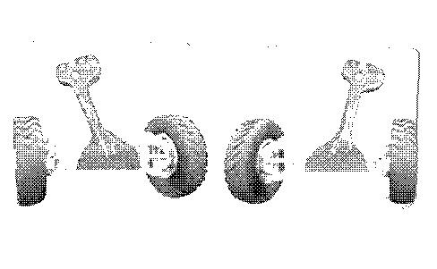
Illustration 1
i07784456
Illustration 2 g01717143
Note: For information on steering alignment refer to Operation and Maintenance Manual, "Operator Controls - Joystick Steering Alignment".
Only operate the machine while you are in the seat. The seat belt must be fastened while you operate the machine. Only operate the controls while the engine is running.
Before you operate the machine, remove the wheel lean locking bolt from the wheel lean lock bracket. Make sure that the frame lock pin is stored in the unlocked position. Articulate the machine. The frame lock link must be removed in order to articulate the machine.
Note: With joystick steering, the position sensors for the steering cylinders limit the steering angle of the axle. This causes the axle stops to not make contact.
Do not use the wheel lean locking bolt and the wheel lean lock bracket in order to center the wheel lean of the machine.
While the ground is being graded, do not operate the machine with the doors open.
While you operate the machine slowly in an open area, check for proper operation of all controls and all protective devices.
Before you maneuver the machine, make sure that no personnel are between the machine and attachments.
Before you move the machine, make sure that no one will be endangered.
When you operate the machine and the worktool in an open area, check for proper operation of the controls and check for operation of the protective devices.
Do not allow riders on the machine while the machine is being operated.
Never use the work tool for a work platform.
Reduce engine speed when you maneuver in tight quarters or when you are going over a hill.
Do not operate the machine close to a cliff. Do not operate the machine near an excavation. Do not operate the machine near an overhang.
When you operate the machine downhill, use two transmission gears less than the transmission gear that is used when you operate the machine up the same hill.
Note: Caterpillar does not recommend that you shift to the NEUTRAL position when you operate the machine downhill. If you shift to the NEUTRAL position the machine may require additional braking effort that could accelerate wear of the service brake components.
Do not allow the engine to overspeed when you operate the machine downhill. If overspeed exists, use the service brake control to decrease the speed to a level that will allow you to downshift. Repeat this process until a stable speed is obtained. Before the engine is pushed beyond a dangerous speed level, the transmission will automatically upshift in order to keep the engine speed within a safe speed range. However, when the maximum gear is reached, the service brakes must be used to control the machine speed and the service brakes must be used to prevent the engine from overspeeding.
Carry attachments approximately 40 cm (15 inches) above ground level. Do not go close to the edge of a cliff, an excavation, or an overhang.
If the machine begins to sideslip downward on a grade, immediately remove the load and turn the machine downhill.
Avoid any conditions that can lead to tipping the machine. The machine can tip when you work on hills, on banks and on slopes. Also, the machine can tip when you cross ditches, ridges, or other unexpected obstructions.
Avoid operating the machine across the slope. When possible, operate the machine up the slopes and down the slopes.
When you operate the machine on a slope, use a low ground speed for maximum control of the machine. When you release the accelerator, there will be immediate reduction in engine rpm and ground speed.
When you operate on a slope, engage the differential lock control. When you operate on a slope, use the throttle lock and use the accelerator control.
On steeper slopes, shift the blade drawbar uphill toward the toe of the moldboard. Articulate the rear frame so the heavy engine frame is on the downhill side of the slope for added stability.
When you operate on a slope less than 2.5:1 start at the top of the slope. Cast the withdrawn material outside of the rear tandem tires to prevent the rear tires from sliding.
Maintain control of the machine. Do not overload the machine beyond the machine capacity.
Never straddle a wire cable. Never allow other personnel to straddle a wire cable.
Know the maximum dimensions of your machine.
Always keep the Rollover Protective Structure (ROPS) installed during machine operation.
Note any needed repairs during machine operation. Report any needed repairs.
Park Brake Override
You can override the steering alignment and you can override the parking brake interlocks in order to move the machine out of danger.
Note: A Warning Category 2S will occur during a park brake override. The alarm will deactivate once the transmission is returned to the NEUTRAL position or machine speed has been detected and the front wheels have been aligned to the left-hand joystick and the steering has become active.
In order to activate the park brake override, follow these steps:
• Push in the bottom of the parking brake switch in order to disengage the parking brake.
• Depress the transmission modulator control (inching pedal). If the left-hand joystick has not been aligned with the front wheels, the steering will not activate. The park brake will not release.
• Bring the machine to high idle by depressing the accelerator control.
• Position the left-hand joystick in the position you want the front wheels to align.
• Select the preferred direction on the transmission control switch.
• Slowly release the transmission modulator control (inching pedal). The park brake will now disengage and the machine will move in the direction that has been selected.
• The front wheels will automatically align to the same angle as the left-hand joystick when machine speed is detected. The steering will then become active.
Note: "1F" and "1R" are the only gears that are available to override the parking brake. Upshifting will not change the selected gear until the front wheels have been aligned to the left-hand joystick and the steering has become active.
Limiting Conditions and Criteria
Limiting conditions are immediate issues with this machine that must be addressed prior to continuing operation.
The Operation and Maintenance Manual, Safety Section describes limiting condition criteria for replacing items such as safety messages, seat belt and mounting hardware, lines, tubes, hoses, battery cables and related parts, electrical wires, and repairing any fluid leak.
The Operation and Maintenance Manual, Maintenance Interval Schedule describes limiting condition criteria that require repair or replacement for items (if equipped) such as alarms, horns, braking system, steering system, and rollover protective structures.
The Operation and Maintenance Manual, Monitoring System (if equipped) provides information on limiting condition criteria, including a Warning Category 3 that requires immediate shutdown of the engine.
The following table provides summary information on several limiting conditions found in this Operation and Maintenance Manual. The table provides criteria and required action for the limiting conditions listed. Each System or Component in this table, together with the respective limiting condition, describes a potential critical failure that must be addressed. Not addressing limiting conditions with required actions may, in conjunction with other factors or circumstances,
result in a risk of personal injury or death. If an accident occurs, notify emergency personnel and provide location and description of accident.
Table 1
System or Component Name
Line, tubes, and hoses
Electrical Wiring
Battery cable (s)
Limiting Condition
End fittings are damaged or leaking. Outer coverings are chafed or cut. Wires are exposed. Outer coverings are swelling or ballooning. Flexible parts of the hoses are kinked. Outer covers have exposed embedded armoring. End fittings are displaced.
Signs of fraying, abrasion, cracking, discoloration, cuts on the insulation
Signs of fraying, abrasion, cracking, discoloration, cuts on the insulation of the cable, fouling, corroded terminals, damaged terminals, and loose terminals
Operator Protective Structure
Seat Belt
Structures that are bent, cracked, or loose. Loose, missing, or damaged bolts.
Worn or damaged seat belt or mounting hardware
Seat Belt
Age of seat belt
Safety Messages Appearance of safety message
Audible Warning
Sound level of audible warning
Criteria for Action
Visible corrosion, loose, or damaged lines, tubes, or hoses. Visible fluid leaks.
Visible damage to electrical wiring
Visible damage to battery cable(s)
Visible damage to structure. Loose, missing, or damaged bolts.
Visible wear or damage
Three years after date of installation
Damage to safety messages making them illegible
Required Action
Immediately repair any lines, tubes, or hoses that are corroded, loose, or damaged. Immediately repair any leaks as these may provide fuel for fires.
Immediately replace damaged wiring
Immediately replace damaged battery cables
Do not operate machine with damaged structure or loose, missing, or damaged bolts. Contact your Cat dealer for inspection and repair or replacement options.
Immediately replace parts that are worn or damaged.
Replace seat belt three years after date of installation
Replace the illustrations if illegible.
Device(s) (if equipped)
Camera(s) (if equipped)
Cab Windows (if equipped)
Dirt or debris on camera lens
Reduced or no audible warning present Immediately repair or replace audible warning devices not working properly.
Dirt or debris obstructing camera view
Dirt, debris, or damaged windows
Mirrors (if equipped)
Dirt, debris, or damaged mirror
Braking System Inadequate braking performance
Dirt or debris obstructing operator visibility. Any damaged windows.
Dirt or debris obstructing operator visibility. Any damaged mirrors.
System does not pass Braking System - Test(s) included in Maintenance Section or in the Testing and Adjusting Manual
Clean camera before operating machine.
Clean windows before operating machine. Repair or replace damaged windows before operating machine.
Clean mirrors before operating machine. Repair or replace damaged mirrors before operating machine.
Cooling System The coolant temperature is too high.
Monitoring System displays Warning Category 3
Contact your Cat dealer to inspect and, if necessary, repair the brake system.
Engine Oil System
Engine system
Fuel System
A problem has been detected with the engine oil pressure.
An engine fault has been detected by the engine ECM.
Monitoring System displays Warning Category 3
Monitoring System displays Warning Category 3
Stop the engine immediately. Check the coolant level and check the radiator for debris. Refer to Operation and Maintenance Manual, Cooling System Coolant Level - Check. Check the fan drive belts for the water pump. Refer to Operation and Maintenance Manual, Belts - Inspect/Adjust/ Replace. Make any necessary repairs.
If the warning stays on during low idle, stop the engine and check the engine oil level. Perform any necessary repairs as soon as possible.
Stop the engine immediately. Contact your Cat dealer for service.
A problem has been detected with the fuel system.
Hydraulic Oil System The hydraulic oil temperature is too high.
Monitoring System displays Warning Category 3
Monitoring System displays Warning Category 3
Stop the engine. Determine the cause of the fault and perform any necessary repairs.
Stop the engine immediately. Check the hydraulic oil level and check the hydraulic oil cooler for debris. Perform any necessary repairs as soon as possible.
Steering System
A problem has been detected with the steering system. (If equipped with steering system monitoring.)
Overall Machine Machine service is required.
Monitoring System displays Warning Category 3
Monitoring System displays Warning Category 3
Move machine to a safe location and stop the engine immediately. Contact your Cat dealer to inspect and, if necessary, repair the steering system.
Stop the engine immediately. Contact your Cat dealer for service. Copyright 1993 - 2024 Caterpillar Inc.
Network For SIS Licensees. Mon Jul 22 10:23:38 UTC+0530 2024
Product: MOTOR GRADER
Model: 150 MOTOR GRADER B56
Configuration: 150 AWD Motor Grader B5600001-UP (MACHINE) POWERED BY C9 Engine
Operation and Maintenance Manual
140M and 150 Motor Grader
Restricted Visibility
SMCS - 7000
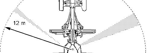
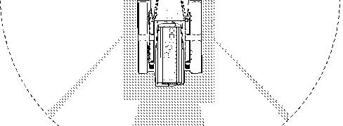
The size and the configuration of this machine may result in areas that cannot be seen when the operator is seated. Illustration 1 provides an approximate visual indication of areas of significant restricted visibility. Illustration 1 indicates restricted visibility areas at ground level inside a radius of 12.00 m (39.37 ft) from the operator on a machine without the use of optional visual aids. This illustration does not provide areas of restricted visibility for distances outside a radius of 12.00 m (39.37 ft).
This machine may be equipped with optional visual aids that may provide visibility to some of the restricted visibility areas. Refer to this Operation and Maintenance Manual, "Mirror" for more information on additional visibility. If your machine is equipped with cameras, refer to this Operation and Maintenance Manual, "Camera" for more information on additional visibility. For areas that are not covered by the optional visual aids, the job site organization must be utilized to minimize hazards of this restricted visibility. For more information regarding job site organization refer to Operation and Maintenance Manual, "Visibility Information".
i04852531
Illustration 1 g02981998
Top view of the machine
Note: The shaded areas indicate the approximate location of areas with significant restricted visibility.
Copyright 1993 - 2024 Caterpillar Inc. All Rights Reserved. Private Network For SIS Licensees.
Mon Jul 22 10:23:22 UTC+0530 2024
Product: MOTOR GRADER
Model: 150 MOTOR GRADER B56
Configuration: 150 AWD Motor Grader B5600001-UP (MACHINE) POWERED BY C9 Engine
Operation and Maintenance Manual
140M and 150 Motor Grader
Visibility Information
SMCS - 7000
Before you start the machine, perform a walk-around inspection in order to ensure that there are no hazards around the machine.
While the machine is in operation, constantly survey the area around the machine in order to identify potential hazards as hazards become visible around the machine.
Your machine may be equipped with visual aids. Some examples of visual aids are Closed Circuit Television (CCTV) and mirrors. Before operating the machine, ensure that the visual aids are in proper working condition and that the visual aids are clean. Adjust the visual aids using the procedures that are located in this Operation and Maintenance Manual. If equipped, the Work Area Vision System shall be adjusted according to Operation and Maintenance Manual, SEBU8157, "Work Area Vision System". If equipped, the Cat Detect Object Detection shall be adjusted according to the Operation and Maintenance Manual, "Cat Detect Object Detection" for your machine.
It may not be possible to provide direct visibility on large machines to all areas around the machine. Appropriate job site organization is required in order to minimize hazards that are caused by restricted visibility. Job site organization is a collection of rules and procedures that coordinates machines and people that work together in the same area. Examples of job site organization include the following:
• Safety instructions
• Controlled patterns of machine movement and vehicle movement
• Workers that direct safe movement of traffic
• Restricted areas
• Operator training
• Warning symbols or warning signs on machines or on vehicles
• A system of communication
i07746368
• Communication between workers and operators prior to approaching the machine
Modifications of the machine configuration by the user that result in a restriction of visibility shall be evaluated.
Copyright 1993 - 2024 Caterpillar Inc. All Rights Reserved. Private Network For SIS Licensees.
Mon Jul 22 10:23:07 UTC+0530 2024
Product: MOTOR GRADER
Model: 150 MOTOR GRADER B56
Configuration: 150 AWD Motor Grader B5600001-UP (MACHINE) POWERED BY C9 Engine
Operation
and Maintenance Manual
140M and 150 Motor Grader
Media Number -SEBU7881-31
Before Operation
SMCS - 7000; 7600
-03/11/2020
Cold ambient temperatures could result in the loss of secondary braking capability due to inadequate hydraulic accumulator nitrogen precharge. The loss of the secondary braking system as well as the main hydraulic pressure will result in little or no braking capability and a potential for injury or death.
It is recommended to perform a brake accumulator check anytime the
Refer to Operation and Maintenance Manual before performing any check of the brake accumulator.
Clear all personnel from the machine and from the area.
Clear all obstacles from the path of the machine. Beware of hazards such as wires, ditches, etc.
Make sure that all windows are clean. Secure the doors in the open position or in the shut position. Secure the windows in the open position or in the shut position.
For the best vision of the area that is close to the machine, adjust the rear view mirrors (if equipped).
Make sure that the machine horn, the backup alarm (if equipped) and all other warning devices are working properly.
Fasten the seat belt securely.
Mon Jul 22 10:22:50 UTC+0530 2024
i02795956