120G MOTOR GRADER
Note: Use Bookmarks panel to navigate
Product: MOTOR GRADER
Model: 120G MOTOR GRADER 87V
Configuration: 120G Motor Grader 87V08360-UP (MACHINE) POWERED BY 3304 Engine
Disassembly and Assembly SINGLE CYLINDER AIR COMPRESSOR
Media Number -REG01343-00
Air Governor
SMCS
Disassemble Air Governor
Updated -18/07/2003
REG013430006
This is the sample of the manual click on the download link for complete manual
For some reason if link does not work download this pdf and then click
4.
5.
6.
NOTE:
7.
1993 - 2025 Caterpillar Inc.
Product: MOTOR GRADER
Model: 120G MOTOR GRADER 87V
Configuration: 120G Motor Grader 87V08360-UP (MACHINE) POWERED BY 3304 Engine
Disassembly and Assembly
SINGLE CYLINDER AIR COMPRESSOR
Media Number -REG01343-00
Crankshaft
SMCS
1.
-01/03/1973
Updated -18/07/2003
REG013430005
Product: MOTOR GRADER
Model: 120G MOTOR GRADER 87V
Configuration: 120G Motor Grader 87V08360-UP (MACHINE) POWERED BY 3304 Engine
Disassembly and Assembly
SINGLE CYLINDER AIR COMPRESSOR
Media Number -REG01343-00
Piston And Rod
Piston And Rod Removal
-01/03/1973
-18/07/2003
REG013430004
9.
Product: MOTOR GRADER
Model: 120G MOTOR GRADER 87V
Configuration: 120G Motor Grader 87V08360-UP (MACHINE) POWERED BY 3304 Engine
Disassembly and Assembly
SINGLE CYLINDER AIR COMPRESSOR
Media Number -REG01343-00
Head Assembly
Remove Head Assembly
3.
REG013430003
Install Head Assembly
3.
4.
5.
6.
7.
1993 - 2025 Caterpillar Inc. All Rights Reserved. Private Network For SIS Licensees.
Product: MOTOR GRADER
Model: 120G MOTOR GRADER 87V
Configuration: 120G Motor Grader 87V08360-UP (MACHINE) POWERED BY 3304 Engine
Disassembly and Assembly
26SI Series Alternator Media
Alternator - Assemble
SMCS - 1405-016
Assembly Procedure
i01167078
Note: Cleanliness is an important factor. Before assembly, all parts should be thoroughly cleaned in cleaning fluid. Allow the parts to air dry. Wiping cloths or rags should not be used to dry parts. Lint may be deposited on the parts which may cause later trouble. Inspect all parts. If any parts are worn or damaged, use new parts for replacement.
Note: Do not strike the diodes. The shock of such an impact can damage the diodes. Use proper tools in order to press the diodes in the mountings.
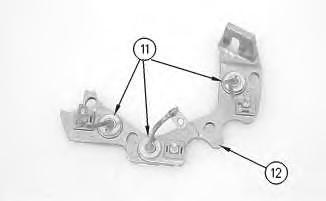
Illustration 1
1. Install 3 diodes (11) in heat sink (12) .
g00628072
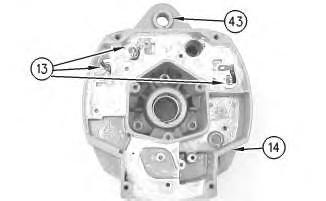
Illustration 2
g00628068
Note: Do not strike the bushing. Shocks from striking the housing can cause damage.
2. Press bushing (43) in housing (14) .
3. Install 3 diodes (13) in housing (14) .
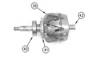
Illustration 3
g00628067
4. Press collar (42) on rotor (39) .
5. Slide retainer (41) on rotor (39) .
6. Press bearing (40) on rotor (39) .
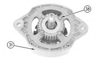
Illustration 4
g00628063
7. Press housing (31) on rotor (39) and bearing (40) .
8. Install 4 screws (38) in housing (31) .
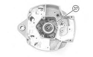
Illustration 5
g00628057
Note: Do not strike the bearing. Shocks from striking the housing can cause damage.
9. Install the inner race. Press bearing (37) into the housing.
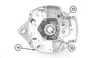
Illustration 6
10. Press cap (36) in housing (14) .
g00628043
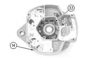
Illustration 7
g00628041
11. Install the coil and support (34) in housing (14). Guide the field leads and the grommet through the hole as the coil is installed in housing (14). Install 3 screws (33) .
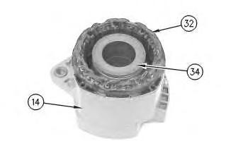
Illustration 8
g00628037
12. Press the stator (32) and housing (14) together. Guide the stator leads and the grommet through the hole as the stator is installed in housing (14) .
Illustration 9
g00628035
Note: Do not damage exposed stator windings or field windings. Bumping the windings or scraping the windings may break the insulation. Broken insulation may create a short circuit or a ground.
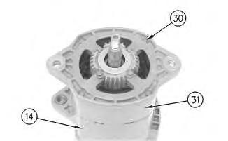
13. Join housing (31) and housing (14). Install 4 bolts (30) .
Illustration 10
g00627853
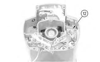
Note: Many of the alternator's internal components are covered with dielectric grease. If the grease is removed, reapply the grease.
11
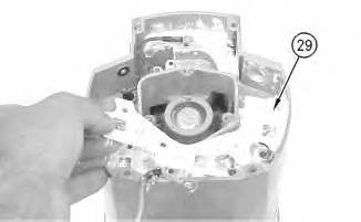
14. Install Insulator (29). Install the heat sink and diode assembly (12) in housing (14) .
12
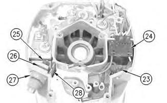
15. Install separator (28) .
16. Install alternator output terminal (27). Install insulator (26). Install the nut and washer (25) .
17. Install diode trio (24) and install screw (23) .
Illustration
g00627855
Illustration
g00627840
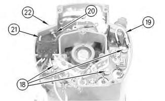
Illustration 13
g00627832
18. Install the 3 screws and insulators (18). Connect wire (19) .
19. If the "R" terminal is used, install the following components: nut (20), lead (21), the washer and terminal (21) .
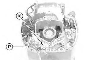
Illustration 14
g00627820
20. Install the screw and insulator (16). Connect capacitor lead (17) .
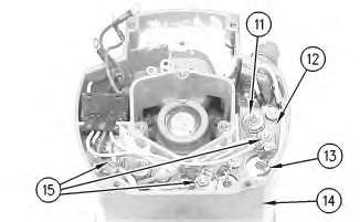
Illustration 15
g00627810
Note: The 3 output diodes (11) are located in heat sink (12). These diodes are identical in polarity. Diode (11) has red insulation on the wire. The 3 ground diodes (13) are located in housing (14). These diodes are identical in polarity. Diode (13) has black insulation on the wire.
21. Connect 6 diode leads. Connect 3 phase leads. Connect 3 stator phase leads. Install 3 nuts (15).
Table 1
Alternator Ground
Negative
Current Flow of the Output Diodes
Lead to the Heat Sink
Current Flow of the Ground Diodes
Housing to the Lead Red Wire Black Wire
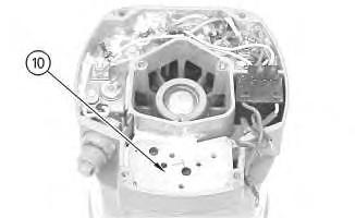
Illustration 16
22. Install mounting plate (10).
g00627808
Illustration 17
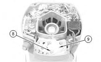
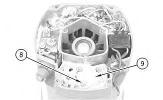
23. Install regulator (9) .
24. Install grounded mounting screw (8) .
g00627804
18
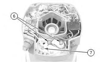
25. Install 2 insulated screws (6). Connect the 3 leads.
Note: The regulator and the mounting plate are coated with dielectric grease. If the grease is removed, reapply the grease.
26. Install nut (7) and connect the wire.
19
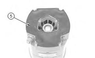
27. Install gasket (5) .
Illustration
g00627796
Illustration
g00627794
20
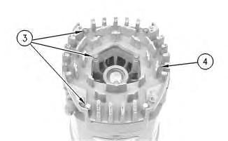
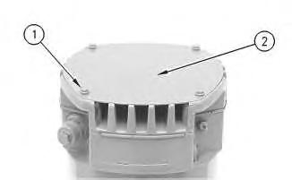
28. Position cover (4). Install 7 screws (3) .
21
29. Position plate (2). Install 4 screws (1) .
30. Install the fan, the pulley, the washer, and the pulley nut.
1993 - 2025 Caterpillar Inc.
Rights Reserved.
Network For SIS Licensees. Tue Feb 18 10:01:33 UTC+0530 2025
Illustration
g00627792
Illustration
g00627790
Product: MOTOR GRADER
Model: 120G MOTOR GRADER 87V
Configuration: 120G Motor Grader 87V08360-UP (MACHINE) POWERED BY 3304 Engine
Disassembly and Assembly
26SI Series Alternator
Alternator - Disassemble
SMCS - 1405-015
Disassembly Procedure
Table 1
Required Tools
Start By:
A. Remove the alternator. Refer to Disassembly and Assembly, "Alternator - Remove" for the machine that is being serviced.
Note: Cleanliness is an important factor. Before the disassembly procedure, the exterior of the component should be thoroughly cleaned. This will help to prevent dirt from entering the internal mechanism.
1. Remove the pulley nut, the washer, the pulley, and the fan.
i01167081
Illustration 1
2. Remove 4 screws (1). Remove plate (2) .
Illustration 2
3. Remove 7 screws (3). Remove cover (4) .
Illustration 3
4. Remove gasket (5) .
g00627790
g00627792
g00627794
Illustration 4
5. Remove 2 insulated screws (6). Remove the 3 leads.
Note: The regulator and the mounting plate are coated with dielectric grease. If the grease is removed, reapply the grease.
6. Remove nut (7) .
Illustration 5
7. Remove grounded mounting screw (8) .
8. Remove regulator (9) .
g00627796
g00627804
This is the sample of the manual click on the download link for complete manual
For some reason if link does not work download this pdf and then click