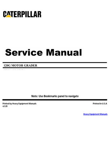
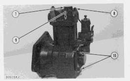
Install Head Assembly
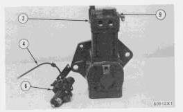
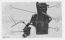
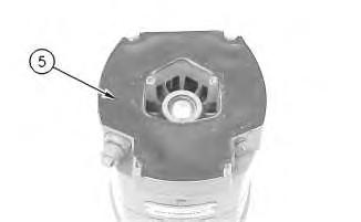
1. Install new gasket (4) on cylinder (2).
2. Install head assembly (1) on cylinder (2).
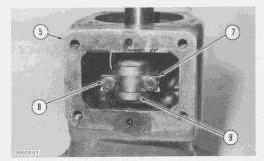
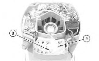
3. Put alignment marks on the cylinder and head assembly together and tighten four nuts (8). Torque for nuts is 14 ± 3 lb.ft. (1.9 ± 0.4 mkg).
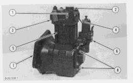
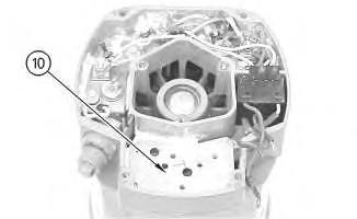
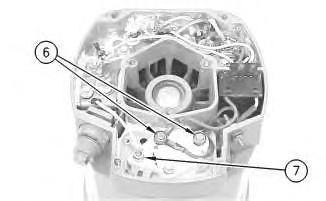
4. Install governor assembly (6) on end cover (5) and tighten bolts (10). Torque for bolts is 10 lb.ft. (1.38 mkg). Connect air line (3) to head assembly (1).
5. Tighten cover (7). Torque for cover is 60 lb.ft. (8.3 mkg).
6. Tighten two set screws (9). Torque for set screws is 50 to 96 lb.in. (57.6 to 110.7 cm.kg).
Disassemble And Assemble
start by:
a) remove head assembly
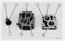
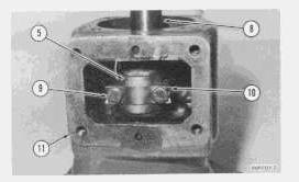
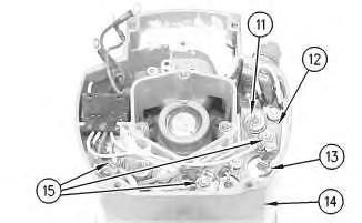
1. Remove cover (7), unloader valve (1) and spring (2) from top half (3) of head and clean the unloader valve.
2. Remove two set screws from top half (3) and hit either top half (3) or bottom half (4) with a soft hammer to separate the head.
3. Remove and clean exhaust valve (5) and spring (6).
4. Remove and clean inlet valve (8) and spring.
5. Clean all of the passages in both top half (3) and bottom half (4).
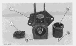
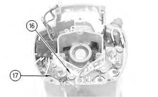
6. Place a new gasket (10), spring (6) and exhaust valve (5) on bottom half (4) of the head.
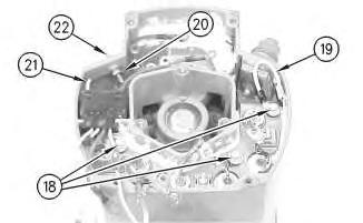
7. Place inlet valve (8) and spring (9) on top half (3) of the head.
8. Carefully put half (3) on half (4). Inlet valve (8) can be moved to the correct location with a rod through the opening for the unloader valve.
9. Install the two set screws to hold the top half (3) and the bottom half (4) of the head together.
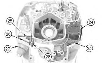
10. Install unloader valve (1), spring (2) and cover (7) in the head.
end by:
a) install head assembly
1993 - 2024 Caterpillar Inc.
Tue Jan 9 14:37:23 UTC+0530 2024
Product: MOTOR GRADER
Model: 120G MOTOR GRADER 87V
Configuration: 120G MOTOR GRADER 87V01138-05274 (MACHINE) POWERED BY 3304 ENGINE
Disassembly and Assembly
SINGLE CYLINDER AIR COMPRESSOR
Media Number -REG01343-00
Publication Date -01/03/1973
Piston And Rod
SMCS - 1065-12; 1065-11
Piston And Rod Removal
start by:
a) remove head assembly
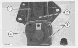
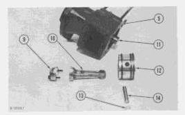
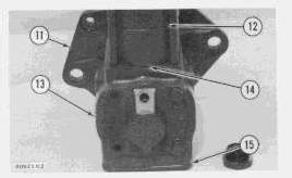
1. Remove cylinder (1) and gasket (2).
2. Remove bolts (3) and end cover (4).
3. Remove four bolts and cover (6).
Date Updated -18/07/2003
REG013430004
4. Put marks on rod cap (9) and rod (10) so rod and rod cap can be installed on crankshaft (11) in the same location as they were removed.
5. Bend lock (7) and remove bolts (8) and rod cap (9). Remove rod (10) and piston (12) from crankcase (5).
6. Mark piston (12) so it can be installed on rod (10) in the same location as it was removed.
7. Remove pin lock (13) and push pin (4) out of piston (12) and rod (10).
8. Clean all parts.
9. Remove piston rings and clean the ring grooves in piston (12) with a piece of hard wood.
Install Piston And Rod
1. The gap for oil ring (1) and the gap for rings (2) is measured with the rings near the bottom in cylinder (12). The gap for each ring is .003 to .009 in. (0.08 to 0.23 mm).
2. Install rings (1) and (2) on piston (3). The gap for each ring must not be near the piston pin bore and each gap must be approximately 120° from the gap in the next ring.
This is the sample of the manual click on the download link for complete manual
DOWNLOAD LINK
For some reason if link does not work download this pdf and then click
3. Install pin (4) in piston (3) and rod (6). Install pin lock (7). The mark put on the piston shows if the location of the piston on the rod is correct.
4. Put rod (6) and piston (3) into crankcase (11). Install rod cap (5). The marks put on the rod cap and rod show the correct location of the rod in crankcase (11).
5. Tighten bolts (9) to a torque of 35 to 40 lb.in. (40.6 to 46.1 cm.kg). Bend lock (10) over bolt heads.
6. Put a new gasket on both end cover (13) and cover (15) and install the covers and gaskets on crankcase (11).
7. Put a new gasket (14) on cylinder (12) and put the gasket and cylinder on crankcase (11). The marks put on the cylinder and crankcase, before the head assembly was removed, must be together.
end by:
a) install head assembly
Product: MOTOR GRADER
Model: 120G MOTOR GRADER 87V
Configuration: 120G MOTOR GRADER 87V01138-05274 (MACHINE) POWERED BY 3304 ENGINE
Disassembly and Assembly SINGLE CYLINDER AIR COMPRESSOR
Media Number -REG01343-00
Publication Date -01/03/1973
Crankshaft
SMCS - 1065-12; 1065-11
Remove Crankshaft
start by:
a) remove head assembly
b) remove piston and rod
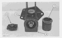
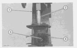
1. A press (1) can be used to remove crankshaft (3) from crankcase (4).
Date Updated -18/07/2003
REG013430005
2. Put a pipe (2), with a bore larger than 1.03 in. (26.2 mm) and a diameter of approximately 2 in. (50.8 mm) with an approximate length of 6 in. (152.4 mm), over the end of crankshaft (3) and on bearing (5).
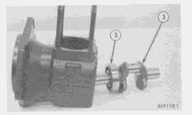
3. Push crankshaft (3) and bearing (5) out of crankcase (4) as a unit.
4. Remove bearing (5).
Install Crankshaft
1. Heat the crankshaft ball bearing in oil to a temperature of not over 350°F (175°C) and put the bearing on crankshaft (3).
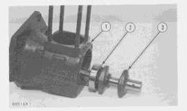
2. Put the bearing and crankshaft (3) into crankcase (1) with the crankcase resting on the large flange end.
3. Outer race (2) of the bearing is pushed into the crankcase with a soft metal rod put at many locations on outer race (2) while hitting the rod with a hammer.
end by:
a) installing piston and rod
b) installing head assembly
Product: MOTOR GRADER
Model: 120G MOTOR GRADER 87V
Configuration: 120G MOTOR GRADER 87V01138-05274 (MACHINE) POWERED BY 3304 ENGINE
Disassembly and Assembly SINGLE CYLINDER AIR COMPRESSOR
Media Number -REG01343-00
Publication Date -01/03/1973
Date Updated -18/07/2003
REG013430006
Air Governor
SMCS - 1065-16; 1065-15
Disassemble Air Governor
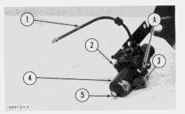
1. Remove air governor from air compressor. Remove air line (1) from body (11).
2. Put a mark (A) on cover (4) and body (11) so the cover can be installed on the body in the correct location.
3. Measure the distance from cover (4) to the top of screw (5) and make a record of the measurement. Loosen the locknut and remove screw (5).
4. Remove four screws (2), identification tag (3), cover (4), spring (6) and spring seat (7).
5. Remove nut (8), plunger (10) and diaphragm (9) as a unit.
6. A rod with a diameter of .12 in. (3.05 mm) put in the hole in plunger (10) is used to hold the plunger when nut (8) is removed.
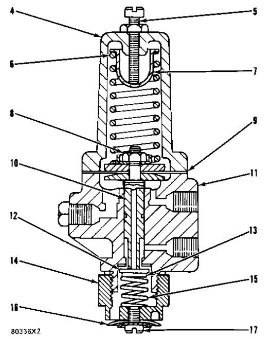
7. Remove screw (17) and exhaust diaphragm (16).
8. Remove exhaust nut (14), spring (15), exhaust valve (12) and spring retainer (13).
9. Clean all of the parts and the passages in body (11) and plunger (10).
Assemble Air Governor
1. Install seal (12) on plunger (11).
2. Put new soft washer (10), follower (9), new diaphragm (8), follower (7), spring guide (5) and new nut (6) on plunger (11).
NOTE: The diaphragm is between the chamfered sides of followers (7) and (9).
3. A rod with a diameter of .12 in. (3.05 mm) put in the hole in plunger (11) is used to hold the plunger when nut (6) is tightened.
4. Lubricant is put on plunger (11) and in body (13). Install plunger in body.
5. Install spring seat (3) in spring (4) and put them on spring guide (5).
6. Install cover (2) over spring seat (3) and spring (4). Mark (A) on cover (2) must be in alignment with mark (A) on body (11) when the four lockwashers and screws in the cover are tightened.
NOTE: The governor identification tag is under one of the four screws.
7. Install screw and nut (1) in cover (2). Make an adjustment for the length of the screw to get the same measurement before the screw was removed from the cover.
8. Install screw and diaphragm washer (20) and new exhaust diaphragm (19) on exhaust nut (18).
9. Install spring (17), spring retainer (16) and new exhaust valve (15) in exhaust nut (18).
10. Install washer (14) and exhaust nut (18), spring retainer and spring in body (13). Install air governor and air line on air compressor.
Copyright 1993 - 2024 Caterpillar Inc.
Rights Reserved. Private Network For SIS Licensees. Tue Jan 9 14:38:33 UTC+0530 2024
Product: MOTOR GRADER
Model: 120G MOTOR GRADER 87V
Configuration: 120G MOTOR GRADER 87V01138-05274 (MACHINE) POWERED BY 3304 ENGINE
Disassembly and Assembly
26SI Series Alternator
Media Number -RENR1252-01
Alternator - Assemble
SMCS - 1405-016
Assembly Procedure
i01167078
Note: Cleanliness is an important factor. Before assembly, all parts should be thoroughly cleaned in cleaning fluid. Allow the parts to air dry. Wiping cloths or rags should not be used to dry parts. Lint may be deposited on the parts which may cause later trouble. Inspect all parts. If any parts are worn or damaged, use new parts for replacement.
Note: Do not strike the diodes. The shock of such an impact can damage the diodes. Use proper tools in order to press the diodes in the mountings.
Illustration 1
1. Install 3 diodes (11) in heat sink (12) .
g00628072
Illustration 2
g00628068
Note: Do not strike the bushing. Shocks from striking the housing can cause damage.
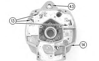
2. Press bushing (43) in housing (14) .
3. Install 3 diodes (13) in housing (14) .
Illustration 3
g00628067
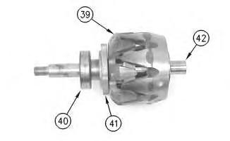
4. Press collar (42) on rotor (39) .
5. Slide retainer (41) on rotor (39) .
6. Press bearing (40) on rotor (39) .
Illustration 4
g00628063
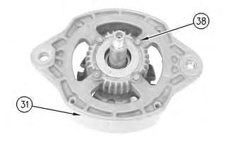
7. Press housing (31) on rotor (39) and bearing (40) .
8. Install 4 screws (38) in housing (31) .
Illustration 5
g00628057
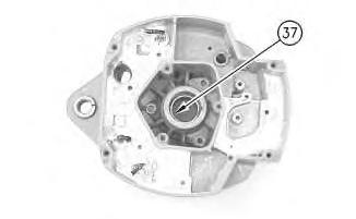
Note: Do not strike the bearing. Shocks from striking the housing can cause damage.
9. Install the inner race. Press bearing (37) into the housing.
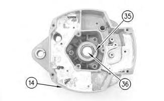
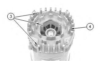
Illustration 6
10. Press cap (36) in housing (14) .
g00628043
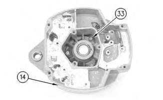
Illustration 7
g00628041
11. Install the coil and support (34) in housing (14). Guide the field leads and the grommet through the hole as the coil is installed in housing (14). Install 3 screws (33) .
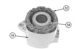
Illustration 8
g00628037
12. Press the stator (32) and housing (14) together. Guide the stator leads and the grommet through the hole as the stator is installed in housing (14) .
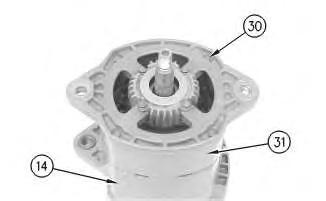
Illustration 9
g00628035
Note: Do not damage exposed stator windings or field windings. Bumping the windings or scraping the windings may break the insulation. Broken insulation may create a short circuit or a ground.
13. Join housing (31) and housing (14). Install 4 bolts (30) .
Illustration 10
g00627853
Note: Many of the alternator's internal components are covered with dielectric grease. If the grease is removed, reapply the grease.
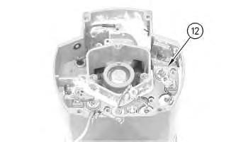
11
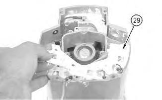
14. Install Insulator (29). Install the heat sink and diode assembly (12) in housing (14) .
12
15. Install separator (28) .
16. Install alternator output terminal (27). Install insulator (26). Install the nut and washer (25) .
17. Install diode trio (24) and install screw (23) .
Illustration
g00627855
Illustration
g00627840
Illustration 13
g00627832
18. Install the 3 screws and insulators (18). Connect wire (19) .
19. If the "R" terminal is used, install the following components: nut (20), lead (21), the washer and terminal (21) .
Illustration 14
g00627820
20. Install the screw and insulator (16). Connect capacitor lead (17) .
Illustration 15
g00627810
Note: The 3 output diodes (11) are located in heat sink (12). These diodes are identical in polarity. Diode (11) has red insulation on the wire. The 3 ground diodes (13) are located in housing (14). These diodes are identical in polarity. Diode (13) has black insulation on the wire.
21. Connect 6 diode leads. Connect 3 phase leads. Connect 3 stator phase leads. Install 3 nuts (15).
Table 1
Alternator Ground
Negative
Current Flow of the Output Diodes
Lead to the Heat Sink
Current Flow of the Ground Diodes
Housing to the Lead Red Wire Black Wire
Illustration 16
22. Install mounting plate (10).
g00627808
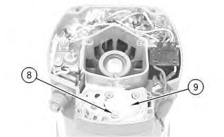
Illustration 17
23. Install regulator (9) .
24. Install grounded mounting screw (8) .
g00627804
18
25. Install 2 insulated screws (6). Connect the 3 leads.
Note: The regulator and the mounting plate are coated with dielectric grease. If the grease is removed, reapply the grease.
26. Install nut (7) and connect the wire.
19
27. Install gasket (5) .
Illustration
g00627796
Illustration
g00627794
20
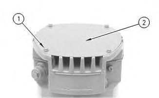
28. Position cover (4). Install 7 screws (3) .
21
29. Position plate (2). Install 4 screws (1) .
30. Install the fan, the pulley, the washer, and the pulley nut.
1993 - 2024 Caterpillar Inc. All Rights Reserved.
Network For SIS Licensees. Tue Jan 9 13:37:42 UTC+0530 2024
Illustration
g00627792
Illustration
g00627790
Product: MOTOR GRADER
Model: 120G MOTOR GRADER 87V
Configuration: 120G MOTOR GRADER 87V01138-05274 (MACHINE) POWERED BY 3304 ENGINE
Disassembly and Assembly
26SI Series Alternator
Media Number -RENR1252-01
Alternator - Disassemble
SMCS - 1405-015
Disassembly Procedure
Table 1
Required Tools
Start By:
A. Remove the alternator. Refer to Disassembly and Assembly, "Alternator - Remove" for the machine that is being serviced.
Note: Cleanliness is an important factor. Before the disassembly procedure, the exterior of the component should be thoroughly cleaned. This will help to prevent dirt from entering the internal mechanism.
1. Remove the pulley nut, the washer, the pulley, and the fan.
i01167081
Illustration 1
2. Remove 4 screws (1). Remove plate (2) .
Illustration 2
3. Remove 7 screws (3). Remove cover (4) .
Illustration 3
4. Remove gasket (5) .
g00627790
g00627792
g00627794
Illustration 4
5. Remove 2 insulated screws (6). Remove the 3 leads.
Note: The regulator and the mounting plate are coated with dielectric grease. If the grease is removed, reapply the grease.
6. Remove nut (7) .
Illustration 5
7. Remove grounded mounting screw (8) .
8. Remove regulator (9) .
g00627796
g00627804
This is the sample of the manual click on the download link for complete manual
DOWNLOAD LINK
For some reason if link does not work download this pdf and then click