Service Information Document Title: Component locations
Function Group: 000
Information Type: Service Information
Date: 11/22/2020
Profile: EC18C Volvo
Component locations Showing Selected Profile Valid for serial numbers Model EC18C Volvo
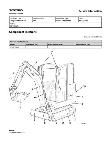
Figure 1 Component locations
Production site
Serial number start
Serial number stop
1
Bucket
9
Arm extension cylinder
2
Bucket cylinder
10
Track chain
3
Arm
11
Undercarriage
4
Dipper arm cylinder
12
Travel motor
5
Boom
13
Superstructure
6
Boom cylinder
14
Battery disconnection switch
7
Dozer blade
15
Engine hood
8
Dozer blade cylinder
16
Working light
Service Information Document Title: Description, general
Function Group: 000
Information Type: Service Information
Date: 11/22/2020
Profile: EC18C Volvo
Description, general Showing Selected Profile Valid for serial numbers Model
Production site
Serial number start
Serial number stop
EC18C Volvo The EC15C, EC17C, EC18C EC20C are compact excavators with track chain drive. The engine is a water-cooled 3-cylinder Volvo diesel engine, type 1.1 DCAE 4 with indirect fuel injection system. The drive movement is provided by two tracks, each of which is driven by an axial piston motor. The track motor of the EC15C has one travel step, and the drive motor of the EC17C, EC18C, EC20C has two travel steps. The hydraulic system is a hydraulic load-sensing system which guarantees complete independence of the individual movements. The superstructure swivel movement is guaranteed by a hydraulic axial piston engine which directly (i.e. without reduction gear) drives a ball-mounted swing ring gear with internal toothing and remote lubrication. The undercarriage of the EC15C and the EC17C consists of a welded H-shaped centre section. The swing ring gear has remote lubrication. The track unit consisting of a track chain, guide wheel including spring package, drive wheel, slide rails, lower running rollers and dozer blade is also part of the undercarriage. The undercarriage of the EC18C and EC20C consists of a welded H-shaped centre section. To increase the stability, the suspension is hydraulically width-adjustable. The dozer blade has blade extensions with fixing brackets in order to allow optimum ploughing results even with the chassis extended. The swing ring gear has remote lubrication. The guide wheel including spring package, drive wheel, slide rails, lower running rollers and dozer blade is also part of the undercarriage.
Figure 1 Compact excavator EC15C, EC17C, EC18C
Figure 2 Compact Excavator EC20C
Service Information Document Title: Hydraulic dieseling
Function Group: cylinders, 091
Information Type: Service Information
Date: 11/22/2020
Profile: EC18C Volvo
Hydraulic cylinders, dieseling Showing Selected Profile Valid for serial numbers Model
Production site
Serial number start
Serial number stop
EC18C Volvo If air enters the hydraulic cylinders during work on the hydraulic system, this can lead to spontaneous ignition, an effect known as dieseling. This occurs if a favourable mixture of air and hydraulic oil is compressed when the piston approaches its end position in the cylinder. A sufficiently high temperature can be reached for the mixture to spontaneously ignite.
NOTICE The dieseling effect may result in burnt piston seals and bushings. In order to prevent dieseling, the lines for the hydraulic cylinders must be bled after work is completed, as follows: Operate the digging equipment several times with no load and full cylinder strokes. Position the dipper arm and bucket cylinders so that any air collects at the cylinder's outlet side, that is, it should be the highest point. The piston should be at the opposite end of the cylinder. Wait approx. 1 minute from the time that the cylinder has reached its position before running the piston towards the outlet side. Repeat 3 to 5 times. The boom cylinders, which cannot be pointed downward, must be run in and out approx. 5 times without bucket load.
NOTICE If the cylinders are pressurized either through lifting of the machine or lifting of a load in the bucket, without first performing the mentioned bleeding movements, the seals will likely be damaged. If a cylinder is to be pressure-tested after a repair, the piston rod should be run in and out a few times before increasing the pressure to testing pressure.
Service Information Document Title: Product plate, description
Function Group: 000
Information Type: Service Information
Date: 11/22/2020
Profile: EC18C Volvo
Product plate, description Showing Selected Profile Valid for serial numbers Model
Production site
Serial number start
Serial number stop
EC18C Volvo The diagrams and descriptions below show the rating plates on the compact excavator. When ordering spare parts and for telephone enquiries and in correspondence, always quote the model designation and product identification number.
This is the sample of the manual if you need complete manual
Click Here to download
Figure 1 Data plates 1. 2. 3.
Data plate Engine product plate Colour code
1. Name plate The data plate indicates the manufacturer's name and address, model/type designation and the 17-digit ID number. 2. Auxiliary data plate (EU countries only) The auxiliary data plate indicates machine weight (in kg), nominal engine power (in kW), year of manufacture, machine serial number and a CE mark. Machine weight The machine weight (in kg) listed on the auxiliary data plate is based on:
¤
Basic machine with 50% of the weight of Volvo-approved extra equipment
¤
Conventional track chain type
¤
Conventional bucket (without load)
¤
Full fuel tank
¤
For reasons of safety, 103% of the machine weight is indicated on the auxiliary data plate.
3. TOPS/ROPS and OPG emblem The emblem is located in the cab on the right B-pillar. The Tip Over Protective Structure (TOPS) and Roll Over Protective Structure (ROPS) protect the operator in the event that the machine tips over or rolls over. Protection is also provided by the Operator Protective Guide OPG. 4. Engine product plate The engine data plate indicates manufacturer information, designation and engine serial number. It is located on the tilt lever trim.
Service Information Document Title: Welding on the machine
Function Group: 091
Information Type: Service Information
Date: 11/22/2020
Profile: EC18C Volvo
Welding on the machine Showing Selected Profile Valid for serial numbers Model
Production site
Serial number start
Serial number stop
EC18C Volvo
NOTICE During electric welding on the machine or attachments connected to the machine, components such as bearings and electric units may be damaged if the ground cable is connected incorrectly. The following actions should be taken before starting electric welding to eliminate these risks: 1. 2.
Turn off the electric power using the battery disconnector. Disconnect the battery. NOTE! Negative and positive poles
3.
Disconnect the following electronic units: – Vehicle control unit (V-ECU) Bring the welder earth connection as close to the weld point as possible, and ensure that no current is flowing via a bearing.
4.
If welding is necessary on the boom or dipper arm, the following basic rules should be followed: 1. 2. 3. 4.
Welding beads should be laid down in the longitudinal direction. If possible, weld in the middle of the metal section and never closer than 80 mm to an edge. Do not weld near the welded connections of the cylinder mounting eyes. Minimum distance from eye's weld to weld for weld lug = 100 mm. Do not weld close to where a metal plate has been bent.
Service Information Document Title: Cleaning prior to repair
Function Group: 170
Information Type: Service Information
Date: 11/22/2020
Profile: EC18C Volvo
Cleaning prior to repair Showing Selected Profile Valid for serial numbers Model
Production site
Serial number start
Serial number stop
EC18C Volvo Clean the exterior of all parts before repairing. Dirt and abrasive dust reduce the efficient work life of the part and lead to costly replacement. Use cleaning fluids and solvents which are suitable for cleaning parts and do not risk the safety of the user. Certain types of fluids damage rubber parts and/or cause skin irritation. The following precautions must be observed to insure hydraulic cleanliness: 1. 2. 3. 4. 5. 6.
Flush hose and tube assemblies with a solvent compatible with hose assemblies. Blow out excess solvent with shop air. Cap hydraulic fittings and protect threads until installation. Cap hoses and tube assemblies until installation. Flush hydraulic reservoir, fuel tank and chain case housings with a suitable solvent to remove any foreign debris. Protect system components from airborne contaminants. Plug all cylinder, valve, reservoir, tank and pump openings until installation. Use clean, filtered motor oil when filling the system. See Lubricants, specifications
Service Information Document Title: Cleanliness, braking hydraulic system
Function Group: and 170
Information Type: Service Information
Date: 11/22/2020
Profile: EC18C Volvo
Cleanliness, braking and hydraulic system Showing Selected Profile Valid for serial numbers Model
Production site
Serial number start
Serial number stop
EC18C Volvo Ensure strict cleanliness during all work. Dry all pipe and hose connections before disconnecting, remove paint scales and similar. Close pipes, hoses, cylinders etc. immediately after disconnecting. Never connect an opened hydraulic hose without cleaning it beforehand.
Service Information Document Title: Coolant
Function Group: 160
Information Type: Service Information
Date: 11/22/2020
Profile: EC18C Volvo
Coolant Showing Selected Profile Valid for serial numbers Model
Production site
Serial number start
Serial number stop
EC18C Volvo Use only Volvo VCS coolant when topping up or changing coolant. Do not mix different coolants or use anti-corrosion additives as this could damage the engine. When using concentrated coolant combined with water, the mixture should be 40-60 % concentrate and 60-40 % water. The percentage of coolant in the mixture must not be below 40 %; see the table below. Anti-freeze protection down to
Percentage of coolant concentrate
-20 °C
40 %
-35 °C
50 %
-46 °C
60 %
The coolant concentrate must not be mixed with water that has a high lime (hard water), salt or metal content. The water for the cooling system must also meet the following requirements: Part name
Value
Total amount of solids
< 340 ppm
Total hardness
< 9.5° dH
Chlorine
< 40 ppm
Sulfate
< 100 ppm
pH value
5.5 - 9
Silicate
< 20 mg SiO /litre
Iron
< 0.10 mg FE/litre
Manganese
< 0.05 mg Mn/litre
Electrical conductive capacity
< 500 µS/cm
Organic content, CODMn
< 15 mg/litre
Use premixed coolant if you do not know the quality of the water. Do not blend different premixed coolants as this could damage the engine.
Service Information Document Title: Fuel, recommendation
Function Group: 160
Information Type: Service Information
Date: 11/22/2020
Profile: EC18C Volvo
Fuel, recommendation Showing Selected Profile Valid for serial numbers Model
Production site
Serial number start
Serial number stop
EC18C Volvo The fuel must as a minimum comply with legal requirements, and the national and international standards for commercial fuel, e.g. EN590 (with nationally adapted regulations for cold behaviour), ASTM 975 No.1D and 2D, JIS KK2204. Sulphur content: to legal regulations (the sulphur content should not however exceed 0.3 weight percent). Bio-diesel Vegetable oil and/or esters, also known as "biodiesel", e.g. methyl ester or rapeseed (RME), is available on many markets as both a pure product and for mixing with diesel fuel. Volvo CE allows the addition of max. 5 % biodiesel in diesel fuels by the oil companies. A biodiesel content that exceeds 5 % could have the following consequences: Increased nitrogen oxide emissions (beyond the legally specified limit) Reduced service life of the engine and injection system Increased fuel consumption Impaired engine power Doubling of oil change intervals Reduced service life of rubber parts, rubber hoses and the fuel system Impaired cold properties of the fuel Limited shelf life of the fuel. If the machine is not used for an extended period of time, the fuel system may become clogged. Warranty The warranty does not apply to damage attributable to the addition of over 5 % biodiesel.
Service Information Document Title: Lubricants, specifications
Function Group: 160
Information Type: Service Information
Date: 11/22/2020
Profile: EC18C Volvo
Lubricants, specifications Showing Selected Profile Valid for serial numbers Model
Production site
Serial number start
Serial number stop
EC18C Volvo Other mineral oils can be used with the recommended viscosity set points. If other oil qualities are used (e.g. biodegradable oil), approval of Volvo CE is required. If the hydraulic system is factory-filled with biodegradable hydraulic oil (see sticker on filler tube), only the oil quality specified on the sticker may be used for topping up. NOTE! BIO oil and mineral oil (hydrocarbon oils) must be disposed of separately. Mixing prohibited! Type of oil Engine
Engine oil Volvo Ultra Diesel API / CD, CF, CF-4, CI-4
Hydraulic system
Hydraulic oil* Volvo Super Hydraulic Oil ISO 6743/4
* To ISO 6743/4HV or DIN 51524HVLP
Viscosity at different temperatures
Bio oil**
** Panolin HLP synth
Travel gear
Gear oil API GL 5
Fuel
Diesel ASTM D975
Lubrication points
Grease ISO 6743/0 Volvo Super Grease Lithium EP2
Cooling system
Antifreeze
Volvo coolant VCS should be used only.
NOTE! Use engine oil of type SAE 10W, SAE 10W/30 or SAE 15W/40 if starting the engine at an ambient temperature of less than 0°C, even if during the day the ambient temperature rises to 10°C. NOTE! Only Volvo CE original anti-freeze coolant should be used. NOTE! Use Volvo genuine coolant when refilling or changing the coolant, otherwise the coolant system can be damaged like corrosion.
NOTICE Volvo Coolant VCS must never be mixed with any other coolant or corrosion protection to avoid damage to the engine.
Service Information Document Title: Repairing hydraulic system
Function Group: 170
Information Type: Service Information
Date: 11/22/2020
Profile: EC18C Volvo
Repairing hydraulic system Showing Selected Profile Valid for serial numbers Model
Production site
Serial number start
Serial number stop
EC18C Volvo When replacing a pump or in case of other interventions in the hydraulic system, during which air may enter into the system, the following must be observed: 1. 2. 3. 4.
The pumps must be filled with oil. Start the engine and run it with low idle speed for approx. 10 minutes, do not operate any hydraulic functions during this time. Operate all hydraulic functions several times at low idle speed of the engine. Operate all hydraulic functions with raised engine speed (approx. 20-25 rps or 1200-1500 rpm) several times to the end positions, but avoid overflowing.
Service Information Document Title: Service and maintenance
Function Group: 170
Information Type: Service Information
Date: 11/22/2020
Profile: EC18C Volvo
Service and maintenance Showing Selected Profile Valid for serial numbers Model
Production site
Serial number start
Serial number stop
EC18C Volvo Thorough maintenance and care as well as the immediate rectification of possible faults are the best guarantee for permanent availability of the machine. This section of the operating instructions describes the maintenance work that can be carried out by the operator. If certain operations require trained personnel and special equipment, this will be specially mentioned in the text. The intervals between inspections, oil changes and lubrication apply as long as the machine is used under normal environmental and operating conditions. Intervals for maintenance and care, see lubrication and maintenance plan. Inspection upon arrival and delivery Before leaving the factory the machine is tested and adjusted. The dealer must additionally carry out an arrival and delivery inspection. Delivery instructions When handing the machine over to the customer, the dealer must browse through and sign the delivery instructions together with the customer.
Figure 1 Arrival and delivery inspection Warranty inspection In order to keep the warranty valid all warranty inspections must be performed. The performance of these inspections is a
prerequisite for the validity of the warranty. Condition test The condition test is carried out in the workshop of an authorized dealer and provides information about the general condition of the machine.
Service Information Document Title: Function Group: Starting engine with booster cables
Information Type: Service Information
Date: 11/22/2020
Profile: EC18C Volvo
Starting engine with booster cables Showing Selected Profile Valid for serial numbers Model
Production site
Serial number start
Serial number stop
EC18C Volvo Battery location The battery is to the right of cab door, behind the upper side panel.
Figure 1 Battery, position Before connecting the jump wires Before connecting the jump wires check the following: Jump wires and pole clamps must be appropriately dimensioned for the size of the battery. Check cables and clamps for damage, corrosion etc. Make sure that cables and clamps are tightly connected. Set the battery disconnect switch to the OFF position. The battery of the running engine must have the same capacity as the battery for the engine requiring jump starting. When starting from another machine make sure that the machines will not touch each other. Connection, jump wires Connect the jump wires as follows:
Figure 2 Jump leads, connect Connect clamp (1) of jump wire (A) with the positive pole (+) of the machine to be jump started. Connect the clamp (2) to the positive pole (+) of the running engine's battery. Connect the clamp (3) of the jump lead (B) to the negative pole (-) of the running engine's battery. Connect clamp (4) with the superstucture of the machine to be jump started. NOTE! Make sure that the clamps are tightly connected with the battery poles. Start the engine with the fully charged battery, then start the engine that needs to be jump started. NOTE! When connecting the cables make sure that the positive (+) and the negative (-) poles do not touch. NOTE! Ensure that the jump leads are correctly connected. Connect the jump lead to the superstructure as far from the battery as possible. Engine starting Start the engine as follows: Battery isolator switch on. Turn the ignition switch to position "START" and start the engine. Start the engine for max. 30 seconds. Wait 2 minutes between two starting attempts. Once the engine has started the jump wires must be removed in reverse order. Disconnection, jump wires Disconnect the cables as follows:
Figure 3 Jump lead, disconnect Disconnect clamp (4) of jump wire (B) from the superstructure. Disconnect clamp (3) from the negative (-) pole of the battery for the running engine. Disconnect the clamp (2) of the jump lead (A) from the positive pole (+) of the running engine's battery.
Disconnect clamp (1) from the positive pole (+) of the battery for the engine that had to be jump started.
Service Information Document Title: Towing, measures
Function Group:
Information Type: Service Information
Date: 11/22/2020
Profile: EC18C Volvo
Towing, measures Showing Selected Profile Valid for serial numbers Model
Production site
Serial number start
Serial number stop
EC18C Volvo If for safety reasons or under certain conditions of use, the machine must be towed from a dangerous situation, the machine can be towed by the towing eye on the underframe. NOTE! To tow the machine, use a suitable steel cable of sufficient strength. The vehicle must be towed (recovered) at a slow speed, where the towing distance should be as short as possible (the tracks do not move).
Figure 1 Towing NOTE! To tow on flat ground, a force of 2900 daN (6520 lbf) is required!
Service Information Document Title: Air cleaner, description
Function Group: 256
Information Type: Service Information
Date: 11/22/2020
Profile: EC18C Volvo
Air cleaner, description Showing Selected Profile Valid for serial numbers Model
Production site
Serial number start
Serial number stop
EC18C Volvo The air filter eliminates dirt from the air before it enters the engine. The air filter requires regular maintenance. The air filter is equipped with an air filter sensor which sends a signal to illuminate the air filter indicator light in the cabin if the filter element becomes clogged. A secondary filter is available as an option.
Figure 1 Air filter 1. 2. 3. 4. 5.
Air cleaner case Secondary filter (option) Filter element Air cleaner sensor Dust valve
Service Information Document Title: Camshaft, description
Function Group: 215
Information Type: Service Information
Date: 11/22/2020
Profile: EC18C Volvo
Camshaft, description Showing Selected Profile Valid for serial numbers Model
Production site
Serial number start
Serial number stop
EC18C Volvo The function of the camshaft is to control the flow of intake air and exhaust gasses in the combustion chambers of the engine. Tappets work off the lobes of the camshaft and drive the push rods to operate the valves. There are six tappets in this engine. Springs on the valves return them to their closed position. The camshaft is mounted on four bearing journals.
Figure 1 Camshaft and components 1. 2. 3. 4. 5. 6. 7.
Tappet Push rod Camshaft Bearing cap Camshaft gear Adjustment spring Screw
Service Information Document Title: Cooling system, description
Function Group: 260
Information Type: Service Information
Date: 11/22/2020
Profile: EC18C Volvo
Cooling system, description Showing Selected Profile Valid for serial numbers Model
Production site
Serial number start
Serial number stop
EC18C Volvo Cooling system diagram The cooling system consists of pipe system, radiator, radiator cap, engine fan rotor, coolant pump, thermostat and expansion tank. The coolant pump transports the coolant through the cylinder block, cylinder head and thermostat. When the coolant has reached the preset operating temperature of the thermostat, this begins to open and the coolant can flow through the radiator. If the coolant temperature is too high, the thermostat sends a signal to the temperature warning light in the cab.
Figure 1 Cooling system diagram 1
Thermostat
5
2
Bypass (until reached)
3
Engine radiator
7
Cylinder block
4
Expansion tank
8
Cylinder head
operating
temperature
is 6
Coolant pump L.O. cooler
Engine fan rotor The engine fan rotor is driven by a V-belt from the crankshaft pulley. The engine fan rotor directs air into the radiator. Engine radiator The radiator acts as a heat exchanger. The coolant absorbs heat in the cylinder block and transfers this to the radiator. In the radiator, the heat is dissipated to the air blown in by the engine fan rotor. Expansion tank The expansion tank catches the coolant overflow from the radiator caused by temperature. The expansion tank has two marks showing the fill level of the coolant system. If coolant must be added, it must be added via the expansion tank. Radiator cap The radiator cap controls the cooling system pressure. When the coolant temperature rises, the system pressure also rises and the volume of the coolant increases. When the system pressure reaches a specific level, the pressure-limiting valve in the radiator cap opens and the coolant returned from the engine is passed to the expansion tank. When the coolant temperature falls, the system pressure also falls and the coolant volume is reduced. The reduced pressure valve in the radiator cap then opens and the coolant can flow back from the expansion tank to the radiator. Coolant pump The coolant pump forces the coolant to circulate through the cylinder block and heads, and returns the coolant to the radiator. Thermostat The thermostat prevents the coolant from circulating in the radiator before the coolant and engine have reached a specific operating temperature. When the engine is cold, the thermostat remains closed and the coolant is not passed through the radiator. The thermostat opens as soon as the engine has reached its operating temperature. This brings the engine to operating temperature as quickly as possible, and avoids engine wear, deposits and emissions.
Service Information Document Title: Crankshaft, description
Function Group: 216
Information Type: Service Information
Date: 11/22/2020
Profile: EC18C Volvo
Crankshaft, description Showing Selected Profile Valid for serial numbers Model
Production site
Serial number start
Serial number stop
EC18C Volvo The forged crankshaft is provided with integrated balancing weights. The gear that drives the engine timing gear and the flange for the flywheel is keyed to the crankshaft.
Figure 1 Crankshaft, description 1
Belt pulley
5
Flywheel
2
Crankshaft gear
6
Connecting rod
3
Crankshaft
4
Ring gear
7
Replace
This is the sample of the manual if you need complete manual
Click Here to download