Operator's Information Document Title: Controls
Information Type: Operator's Information
Date: 12/3/2020
Profile: EC160D L Volvo
Location: Tiltrotator control system/Appendix
Controls Showing Selected Profile Valid for serial numbers Model
Production site
Serial number start
Serial number stop
EC160D L Volvo
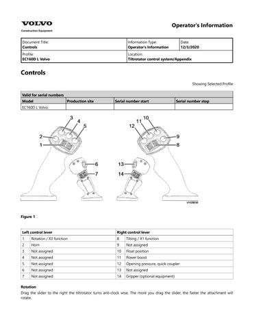
Figure 1
Left control lever
Right control lever
1
Rotation / X3 function
8
Tilting / X1 function
2
Horn
9
Not assigned
3
Not assigned
10
Float position
4
Not assigned
11
Power boost
5
Not assigned
12
Opening pressure, quick coupler
6
Not assigned
13
Not assigned
7
Not assigned
14
Gripper (optional equipment)
Rotation Drag the slider to the right the tiltrotator turns anti-clock wise. The more you drag the slider, the faster the attachment will rotate.
Figure 2 Horn Press the button to sound the horn. Not assigned Not assigned Not assigned Not assigned Not assigned Tilting
Figure 3 Drag the slider to the right to lower the right hand side of the attachment. Drag the slider to the left to lower the left hand side of the attachment. The more the slider is moved, the faster the attachment will tilt. Not assigned Float position Press button to activate and deactivate the float position. A control lamp on the display unit lights up. Power boost Press button to activate the power boost function. A control lamp on the display unit lights up. Opening pressure, quick coupler Press this button to give hydraulic flow to the tiltrotator’s quick coupler for locking and unlocking. The tiltrotator must be mounted and the control lockout lever in the upper position to get a hydraulic flow in the tiltrotator. This is needed for the locking and unlocking of the quick coupler. Not assigned Gripper (optional equipment)
Figure 4 Drag the slider to the right to open the gripper. The more the slider is moved the faster the gripper moves. NOTE! Make sure that the optional pedal (X1) is in locked position when it is not used in order to prevent unwanted manoeuvres.
Operator's Information Document Title: Display unit
Information Type: Operator's Information
Date: 12/3/2020
Profile: EC160D L Volvo
Location: Tiltrotator control system/Appendix
Display unit Showing Selected Profile Valid for serial numbers Model
Production site
Serial number start
Serial number stop
EC160D L Volvo The display unit is a touch screen interface. When the buttons are available, they are shown in colour. When a button is currently unavailable, it is greyed out. At the top of the display, your current working profile and level is indicated. Symbols in menu
Figure 1
1. 2. 3. 4. 5. 6. 7.
Warning indicator Error indicator Menu Help OK Cancel/Return Arrows
1.
Warning indicator The warning indicator will light up when the system detects a state that is not normal. It is still possible to operate the tiltrotator, but only operate the tiltrotator in a safe way and make sure that you will not create a risk to the machine or bystanders until you have detected and solved the problem or the cause for the warning indicator. Error indicator The error indicator lights up if the system detects an error. Some functions or the complete tiltrotator may stop working depending on what error occurs; please refer to the error code explanation for further instructions. To get more information about the error, tap Menu followed by Troubleshooting on the display. Menu
2.
3.
4. 5. 6.
7.
Go to menus for further settings. Help Help information about the current screen. OK Save the settings and go back to main menu. You can alter several different settings before you press OK. Cancel/Return Cancel and return without saving. NOTE! After ten minutes of non-interaction the screen will automatically return to operation mode. Arrows Use the arrows to navigate between the pages in the menu. Figures in between the arrows indicate current page and total number of pages.
Operator's Information Document Title: High sulphur fuel conversion kit
Information Type: Operator's Information
Date: 12/3/2020
Profile: EC160D L Volvo
Location: High sulphur fuel conversion kit/Appendix
High sulphur fuel conversion kit Showing Selected Profile Valid for serial numbers Model
Production site
Serial number start
Serial number stop
EC160D L Volvo This Operator’s Manual Appendix must be kept with the machine Operator’s Manual. If the conversion kit decal is installed on the machine, it means that the emissions controlled engine has been converted to run on fuel with a sulphur content of up to 10000 ppm (1%). Parts for the exhaust aftertreatment system have been disconnected, removed and/or replaced. Related display messages are blocked in the machine software. NOTE! The high sulphur conversion kit is permanent. The engine cannot be converted back to the original emission certification and cannot legally be used in the EU, the US or other countries with emissions regulations for non-road engines. Machines with engines that have been converted to run on fuel with a high sulphur content can be identified by two conversion kit decals. The conversion kit decals are installed on the frame next to the machine PIN plate and on the engine next to the engine identification plate.
Figure 1 Conversion kit decal If the machine has been converted, disregard information in the Operator’s Manual and on machine decals related to: regeneration exhaust aftertreatment system CE marking emissions compliance sound power levels sound pressure levels
This is the sample of the manual if you need complete manual
Click Here to download
Operator's Information Document Title: Menu functions
Information Type: Operator's Information
Date: 12/3/2020
Profile: EC160D L Volvo
Location: Tiltrotator control system/Appendix
Menu functions Showing Selected Profile Valid for serial numbers Model
Production site
Serial number start
EC160D L Volvo Tap the tool icon to enter the main menu below.
Figure 1
1
Speed
5
Clinometer
2
Brightness
6
Troubleshooting
3
Profile
7
Information
4
Layout
8
Language
Speed With this menu you can adjust the maximum speed of the different functions.
Serial number stop
Figure 2
1. 2.
Choose the function you want to adjust the speed of in the drop-down menu. Move the slider to the right to increase the maximum speed and to the left to decrease it. NOTE! The speed may have to be reduced on the extra function to allow handling of work tools with limited hydraulic capabilities.
3.
Press OK to save the settings and go back to main menu or cancel to quit without saving settings.
Brightness You can choose between two different modes for the screen:
Figure 3
A. B.
Day mode Night mode
Adjust the brightness (C) by dragging the slider next to the symbol. Change the time before the screen will go to sleep (D) by dragging the slider next to the symbol. Drag the slider all the way to the right to turn of the screen saver completely. Press OK to save the settings and go back to main menu or cancel to quit without saving settings. Profile A profile stores settings for different work tools or different operator.
Figure 4 You can save up to four different profiles. This enables you to quickly shift settings for different attachments or operators. NOTE! All settings made are stored only to the profile currently active. The active profile is shown in the upper right corner of the screen. Change profile: 1. 2. 3.
Use the drop-down menu and tap on “Change profile”. Press the profile that you want to activate. Press OK to save the settings and go back to main menu or cancel to quit without saving settings.
Rename profile:
Figure 5
1. 2. 3. 4.
Use the drop-down menu and tap on “Change name”. Press the profile name you want to change. Write the new name using the on-screen keyboard. Press OK to save the settings and go back to main menu or cancel to quit without saving settings.
Copy profile: 1. 2.
Use the drop-down menu and tap on “Copy profile”. Choose a profile that you want to copy the settings from. NOTE! The saved settings in the target profile will be deleted.
3. 4.
Choose a target profile that you want to copy the settings to. Press OK to save the settings and go back to main menu or cancel to quit without saving settings.
Reset profile: NOTE! When you reset a profile your settings will be deleted and exchanged to the original settings. The profile name will be changed to Default. 1. 2. 3.
Use the drop-down menu and tap on “Reset profile”. Tap the profile that you want to reset. Press OK to save the settings and go back to main menu or cancel to quit without saving settings.
Layout
Figure 6 Layout of left hand side joystick, press right arrow to see the right hand joystick. In the layout menu you can find information about how your joystick controllers, sliders and push buttons are configured. R1-R4 indicate the sliders. 1-14 indicate the push buttons. RX+X indicates that the function is controlled by simultaneously using a push button and a slider. Use the arrows to switch between the menu for left and right joystick control. Press cancel to return to main screen. Clinometer
Figure 7 The clinometer indicates how your attachment is positioned. NOTE! According to machine type, this function can not be supported. The tilt angel is displayed by the indicator line (A).
The bucket angle is displayed by the indicator (A) moving up or down. The rotation angle is indicated by the dot (B) circulating round the perimeter of the clinometer. A desired reference value can be set as follows: 1. 2.
Press the “Set” button to indicate a reference position, e.g. the axis is set to 0. When you operate the attachment values for tilt, bucket and rotation is indicated in relation to the chosen reference position.
Troubleshooting
Figure 8 With the troubleshooting menu, you can get help in solving system errors. You can also test that the signals coming in from the joysticks are correct and verify the outputs signals. See active errors: Press the “Error code” for the error and an explanation of the error code will appear, further you can get suggested solutions to solving the problem. See previous errors: Errors which have been resolved is shown in a separate list. You can delete the list by pressing “Erase”.
Figure 9
Check input signals: By activating buttons, sliders and switches you can test the joystick input signals. Beside the two joysticks the following is represented in the middle of the display: “Safety gate”: Control lockout lever “Tool lock 1/2”: Quick coupler switch Green indicates that the signal is okay. For sliders you can also see the % value - normal values are between 1–100%. If no
indication is visible when a slider/switch is activated it is either inactive or the slider/switch is faulty or the cable or wire is broken. Please contact a workshop authorized by Volvo.
Figure 10
Check output signals: The system converts the input signals to control signals for the various functions. Green indicates that the signal seems to be okay. Yellow indicates that the system does not have contact with the particular output. This means that the cable, valve or connector is broken. Red indicates short circuit, which means that the cable or connector is probably faulty. Fixed level outputs are also indicated with the current mA. If the output is digital a low level will be indicated with NA. Information This menu shows various system information for the system and its components, such as power, software version etc. Language Choose language 1. 2.
Press the button corresponding to the language you wish. (The current language is darker with a green edge.) Press OK to save the settings and go back to main menu or cancel to quit without saving settings.
Operator's Information Document Title: Oil change interval
Information Type: Operator's Information
Date: 12/3/2020
Profile: EC160D L Volvo
Location: High sulphur fuel conversion kit/Appendix
Oil change interval Showing Selected Profile Valid for serial numbers Model
Production site
Serial number start
Serial number stop
EC160D L Volvo If the machine has been converted, some maintenance intervals may have changed. Use the maintenance intervals listed below. [1] Engine oil and filter change intervals Oil grade [T1]
Volvo Engine Oil VDS-4.5
Change intervals (Sulphur content in the fuel) <15 - 3000 ppm
3000 ppm
-
5000 >5000 ppm
every 500 hours
every 250 hours
every 125 hours
every 250 hours
every 125 hours
every 75 hours
Other approved VDS-4.5 oil Volvo Engine Oil VDS-4 Other approved VDS-4 oil Volvo Engine Oil VDS-3 Other approved VDS-3 oil API CJ-4 or API or CK-4 or ACEA E9
[T1] Refer to the Operator’s Manual for recommended lubricant specifications based on ambient operating temperature. [1]English
Operator's Information Document Title: Operating
Information Type: Operator's Information
Date: 12/3/2020
Profile: EC160D L Volvo
Location: Tiltrotator control system/Appendix
Operating Showing Selected Profile Valid for serial numbers Model
Production site
Serial number start
Serial number stop
EC160D L Volvo The machine’s quick coupler lock (1) can not be opened when the electrical connector on the tiltrotator is connected properly to the machine. This is a safety feature to ensure opening is not done by mistake when operating the tiltrotator. Instead the quick coupler switch is used for attaching the attachment to the tiltrotator’s quick coupler (2). To be able to open the machine’s quick coupler it is necessary to install a safety plug instead of the tiltrotator’s electrical connector on the dipper arm. Without safety plug or electrical connector installed the quick coupler switch will not function.
WARNING Risk of crushing. Hydraulic or mechanical failure could cause the attachments to fall, resulting in severe personal injury or death. Always place the attachment on the ground when installing or removing it and make sure nobody enters the working area. Installing the tiltrotator 1.
Attach the tiltrotator to the machine’s quick coupler (1) according to information about quick couplers in the Operator’s Manual.
Figure 1
This is the sample of the manual if you need complete manual
Click Here to download
1. 2.
Machine’s quick coupler Tiltrotator’s quick coupler
A. B. C. D. E. F. G.
Tiltrotator disconnected Tiltrotator connected Holder for safety plug Safety plug Electrical connector for tiltrotator Stop valve for X1 Hydraulic connectors
NOTE! Be careful so no hydraulic or electrical lines are damaged on the tiltrotator. 2. 3. 4. 5. 6. 7. 8.
Place the tiltrotator on the ground and position the machine for best access to the hydraulic connectors. Stop the engine and depressurize the hydraulic system. Connect the hydraulic lines on the tiltrotator to the connectors (G) on the machine. Start with the one on the right hand side (tank side). Open the stop valves for X1 (F) with a wrench slowly. There is one stop valve on each side. Flip up the lock to remove the safety plug (D) on the dipper arm. Store the safety plug in the holder (C) to the right. Connect the electrical connector (E) on the tiltrotator to the dipper arm. Install the attachment according to information in the machine’s Operator’s Manual about the quick coupler.
Figure 2
Stop valve for X1, positions 1. 2.
Open Closed
NOTE! Remember that the hydraulic system must be pressurized in order to make the quick coupler lock or unlock. Build up the pressure by operating any of the features in tiltrotator with the joystick or pressing the button for opening pressure quick coupler. Removing the tiltrotator 1.
Remove the attachment from the tiltrotator’s quick coupler (2).
Figure 3
1. 2.
Machine’s quick coupler Tiltrotator’s quick coupler
A. B. C. D. E. F. G.
Tiltrotator disconnected Tiltrotator connected Holder for safety plug Safety plug Electrical connector for tiltrotator Stop valve for X1 Hydraulic connectors
2. 3. 4. 5. 6.
Put the tiltrotator flat on the ground. Stop the engine and depressurize the hydraulic system. Close the stop valves for X1 (F) with a wrench slowly. There is one stop valve on each side. Remove the hydraulic lines (G) from the dipper arm. Remove the electrical connector (E) and flip up the lock to insert the safety plug (D). NOTE! When the safety plug is installed the machine will work as described in Operator’s Manual, with the exception of the control levers, which is shown on page Controls.
7.
Remove the tiltrotator from the machine’s quick coupler (1) according to information in the Operator’s Manual.
NOTE! Be careful so no hydraulic or electrical lines are damaged on the tiltrotator.
Operator's Information Document Title: Presentation
Information Type: Operator's Information
Date: 12/3/2020
Profile: EC160D L Volvo
Location: Tiltrotator control system/Appendix
Presentation Showing Selected Profile Valid for serial numbers Model
Production site
Serial number start
Serial number stop
EC160D L Volvo This appendix contains information about the Volvo Tiltrotator Control System available as optional equipment on EC55C, ECR58D, ECR88D, EC140D, EC160D, EC180D, EC220D, EC250D, EC300D, ECR145D and ECR235D. The Tiltrotator Control System is specifically designed to operate tiltrotators. Functionality for other tools or functions may be added with the use of additional integrated hardware and software options. All other information for the machine, such as general safety instructions and maintenance, can be found in the machine’s Operator’s Manual. All other information for the tiltrotator, such as operating, specifications and maintenance can be found in the documentation from the supplier of the tiltrotator. When the tiltrotator is disconnected a plug needs to be installed in the electrical connector on the dipper arm for the machine to function as described in the machine’s Operator’s Manual, including the functionality for X1 and X3. NOTE! Do not update the Software of S-ECU (Tiltrotator ECU or Cabin module), unless otherwise announced officially by Volvo Construction Equipment. Any unofficial software update may affect the integrity of the machine and/or the ability of the machine to perform as designed. NOTE! Volvo Construction Equipment is not liable for any fault or problem of the tiltrotator assembly. Contact the supplier of the tiltrotator for more information.
Operator's Information Document Title: CareTrack with anti-theft
Information Type: Operator's Information
Date: 03-12-2020
Profile: EC160D L Volvo
Location: Display unit/Instrument panels
CareTrack with anti-theft Showing Selected Profile Valid for serial numbers Model
Production site
Serial number start
Serial number stop
EC160D L Volvo CareTrack (optional equipment) CareTrack is a telematics system enabling machine owners to track and monitor machines from a computer with connection to the Internet, regardless of how far away the machine is. By logging in to the CareTrack portal, it is possible to get information about the machine’s condition, at any time. For example, when they have been used, at what work mode they have been operated, how much fuel they have consumed, or the exact positions of the machines. CareTrack uses GSM (Global System for Mobile communication, same as is used for mobile telephones) for direct connection to the machine’s built-in computers (ECUs). By using a combination of the GSM-net and the satellite-based GPS-system (Global Positioning System), CareTrack can move information from a machine to a computer connected to the Internet, via the CareTrack portal. The CareTrack unit consists of a built-in GPS receiver, satellite modem, and two antennas. When the machine is running, it is online, and can be localized - at any time and in any place. After having logged in via the secure CareTrack portal, the machines can be tracked and monitored online, in real-time. However, the machine must be running to send real-time information, all other information is sent within 24 hours. CareTrack is available on several continents, but in principle CareTrack works everywhere there is GSM coverage. Where there is no coverage, satellite link can be used. CareTrack with anti-theft (optional equipment)
Figure 1 CareTrack unit 1. 2. 3.
W-ECU Satellite modem Back-up battery
CareTrack with anti-theft function works by W-ECU, web portal, Volvo's service tool (Tech Tool), V-ECU, and I-ECU. The antitheft function is to immobilize the machine according to the following conditions. Wrong code alarm Geofence broken Timefence broken
System tampered Machine movement Battery power lost Remote immobilization No coverage ECU tampered Machine immobilized information
Figure 2 This screen is to warn the operator when the machine is immobilized. To get more information about the message on the screen, press the SELECT button. To go back to the previous screen, press the ESC button. Wrong code alarm
Figure 3
Enter operator code Wrong code Retry in XX : XX When the machine is turned on, the authorization code display is shown if the anti-theft system is selected as an optional equipment. Wrong code display appears on the I-ECU when the operator or machine owner has entered the wrong code. After 3 inputs of an incorrect code, the authorization will be limited for 5 minutes and a wrong code alarm will send to the CareTrack portal. The default code lock's delay time is 2 minutes and it can be changed with Volvo's service tool. There are 3 levels for authorizing machine operation. Level 1: This is the operator code with 4 digits which are set by the machine owner in I-ECU menu or CareTrack portal. Level 2: This is a machine owner code with 6 digits which are set using Volvo's service tool. Level 3: This is a one-time authorization code with 8 digits which are obtained from the CareTrack portal. Geofence broken
Figure 4
When the machine owner activates a geofence in the CareTrack portal and the machine is outside the geofence, the geofence broken message will appear on the I-ECU. When the machine owner activates a geofence and configures automatic immobilization in the CareTrack portal and the machine is outside the geofence, the geofence broken warning message will appear on the I-ECU and the machine is immobilized at the next start.
Figure 5 W-ECU sends the warning message to the CareTrack portal. The warning condition is revoked when the machine is inside the geofence. Timefence broken
Figure 6
When the machine owner activates a timefence in the CareTrack portal and the machine is outside the timefence, the timefence broken message appears on the I-ECU. When the machine owner activates a timefence and configures automatic immobilization in the CareTrack portal and the machine is outside the timefence, the timefence broken warning message appears on the I-ECU and the machine is immobilized at the next start.
Figure 7 W-ECU sends the warning message to the CareTrack portal.
The warning condition is revoked when the machine is inside the timefence. System tampered
Figure 8
Figure 9
GPS tampered If the machine lost GPS antenna cable connection, the V-ECU informs the operator with the warning message on the I-ECU and activates machine immobilization. GSM/3G tampered If someone cuts the GSM/3G antenna, the V-ECU informs the operator with the warning message on the IECU and activates machine immobilization. Open box detection If someone tries to open the W-ECU enclosure, the V-ECU informs the operator with the warning message on the I-ECU and activates machine immobilization. SIM card tampered If someone removes or changes the SIM card, the V-ECU informs the operator with the warning message on the I-ECU and activates machine immobilization. NOTE! W-ECU sends the warning message to the CareTrack portal. Machine movement
Figure 10
If the machine moves 100 metres without its own power, the W-ECU detects the machine movement and the machine will be immobilized and W-ECU sends the warning message to the CareTrack portal. After the machine has been immobilized, the warning message will appear on the I-ECU before the authorization code display. The machine owner or dealer can mobilize (de-immobilize) the machine with codes for Level 2 and Level 3. Battery power lost
Figure 11
If the W-ECU is disconnected from battery power cable or detects the battery supply voltage lower than 8 V, the WECU operates on its own internal battery. The V-ECU activates machine immobilization and the red warning message will appear on the I-ECU. W-ECU sends the warning message to the CareTrack portal. The warning condition is revoked when the trigger has disappeared. Remote immobilization
Figure 12
If dealer (level 3 code owner) requests machine immobilization in the CareTrack portal, the remote immobilization warning message will appear on the I-ECU and the machine is immobilized at the next start. If machine owner requests machine immobilization in the CareTrack portal, the remote immobilization warning message will appear on the I-ECU and the machine is immobilized at the next start.
Figure 13
No coverage
Figure 14
If the W-ECU has not been connected to the CareTrack portal for the number of days set by Volvo's service tool, the machine will be immobilized. The no coverage days warning will appear at every start with number of remaining days set by Volvo's service tool. The active trigger and no coverage counter can be reset using a one-time authorization code or Volvo's service tool. If the machine gets a connection to the CareTrack portal, the machine will be mobilized (de-immobilized) and the coverage counter is reset. ECU tampered
Figure 15
When the machine is turned on, the W-ECU and V-ECU check the machine serial number of the other ECUs. If the machine's serial number is different, the V-ECU prevents machine start immediately and a warning message will appear on the I-ECU. If the W-ECU is disconnected from key on cable and the machine is turned on, the V-ECU prevents machine start immediately and a warning message will appear on the I-ECU. The warning condition is revoked when the trigger has disappeared. Anti-theft system, setup menu This menu is used for setting up the anti-theft system. This menu is divided into two sub-menus as follows. 1.
One time authorization: This is used for setting a one-time code when the machine is immobilized with level 3 remote immobilization or no coverage warning condition. The machine owner gets the one-time code from the dealer. The dealer gets an 8-digit random code in the CareTrack portal with 8-digit seed (number shown on I-ECU) and machine serial number.
Figure 16
Current 8-digit seed
Enter one-time code 2.
Owner menu: The machine owner's authorization code is required to access this menu. (6 digits)
Figure 17
Enter owner code Read operator code: This sub-menu allows the machine owner to read the current operator code. (4 digits)
Figure 18
Operator code Generate operator code: This sub-menu allows the machine owner to generate a random operator code. (4 digits)
Figure 19
New operator code Set operator code: This sub-menu allows the machine owner to set a preferred operator code. (4 digits)
Figure 20
Enter new operator code Service action: This sub-menu is used for service actions such as moving the machine, replacing the machine battery and disconnecting the GPS antenna. This disables the anti-theft system except for remote immobilization, no coverage immobilization and machine serial number check, and the W-ECU informs the CareTrack portal. The anti-theft system will be activated when the ignition is turned on the next time.
Figure 21
Service action on Immobilizer off Popup messages for anti-theft system Info screen for anti-theft system Info screen and indicator will be displayed as below. The I-ECU screen is replaced by a white-outlined box with title of "Anti-theft system". The buzzer alarm sounds on only 1 time. This screen disappears automatically in 2 seconds.
Geofence broken Go back to the site
Timefence broken Stop operating
Check screen for anti-theft system Check screen and indicator will be displayed as below. The I-ECU screen is replaced by a yellow-outlined box with title of "Anti-theft system". The buzzer alarm sounds on 4 times. To go back to the user's screen, press the ESC button.
Geofence broken Immo at next stop
Timefence broken Immo at next stop
Anti-theft sys tampered Immo at next stop
GPS cable cut Immo at next stop Warning screen for anti-theft system Warning screen and indicator will be displayed as below. The I-ECU screen is replaced by a red-outlined box with title of "Anti-theft system". A warning alarm sounds when the "Warning screen" pops up. Warning screen and buzzer alarm can not be canceled by pressing ESC button. NOTE! Contact an authorized Volvo Construction Equipment dealer or workshop immediately.
Machine immobilized
Machine inoperable Contact service
Geofence broken Timefence broken System tampered Machine movement Battery power lost Remote immobilization No coverage
Electronic power lost Inoperable at next stop
Machine immobilized Contact service
Requested by the owner Immo at next stop
No coverage Days left for immo: XX
No coverage Immo at next stop
Requested remotely Immo at next stop
Operator's Information Document Title: Control types for X1 and X3 operation
Information Type: Operator's Information
Date: 03-12-2020
Profile: EC160D L Volvo
Location: Display unit/Instrument panels
Control types for X1 and X3 operation Showing Selected Profile Valid for serial numbers Model
Production site
Serial number start
Serial number stop
EC160D L Volvo Toggle
Figure 1
Control types for X1 and X3 Push Proportional If a machine has a "proportional control option" for X1 or X3, the user can set one of these 3 types. Otherwise the user is only allowed to set one of 2 types that are "Toggle" or "Push". Refer to page Controls for more details on optional levers. Control using on/off switch on the control lever
Figure 2
Control lever with on/off switch 1.
2.
Toggle type in I-ECU Actuator for X1 or X3 is activated by pressing the on/off switch on the control lever and it will stay active even when the switch is released. The actuator will be deactivated when the same switch is pressed again or the other switch for opposite direction is pressed. Push type in I-ECU
Actuator for X1 or X3 is activated while the on/off switch is pressed (On position). The function will be deactivated when the on/off switch is released. Control using proportional switch on the control lever
Figure 3
Control lever with proportional switch 1.
2.
Toggle and Push-button type in I-ECU These controls with proportional switch are similar as the ones with on/off switch but it has a special point to activate the actuator because the proportional switch also has a proportional value. In toggle type, the actuator will be activated by moving the proportional switch to one direction and it will be deactivated when the switch is moved to same direction again or to opposite direction. Proportional type in I-ECU Actuator for X1 or X3 is activated proportional to the movement of the proportional switch.
Operator's Information Document Title: Display unit
Information Type: Operator's Information
Date: 03-12-2020
Profile: EC160D L Volvo
Location: Display unit/Instrument panels
Display unit Showing Selected Profile Valid for serial numbers Model
Production site
Serial number start
Serial number stop
EC160D L Volvo Startup sequence Initial startup sequence is done as follows. A.
Volvo logo If the user turns the ignition switch to ON position, the Volvo logo on the I-ECU screen lights up for a few seconds.
This is the sample of the manual if you need complete manual
Click Here to download