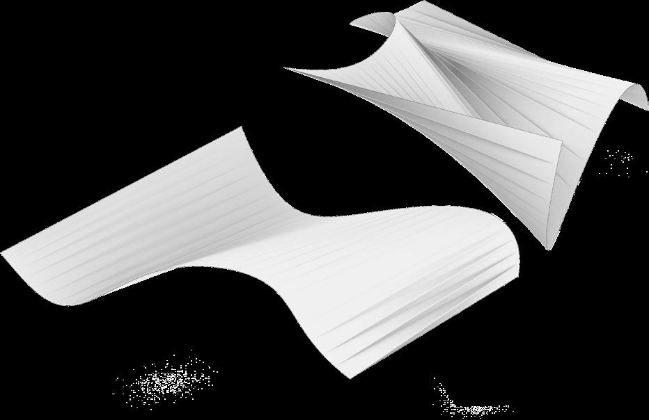
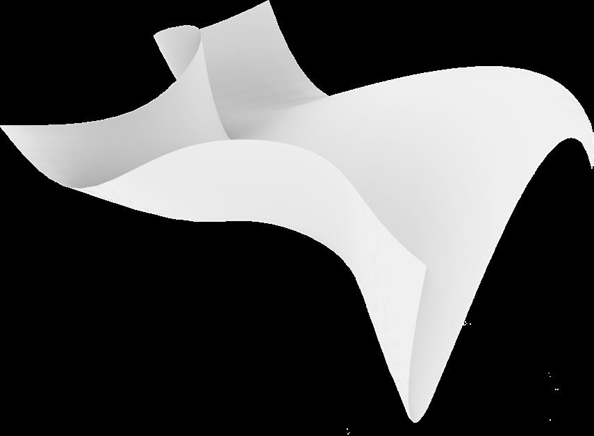
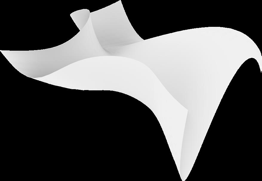
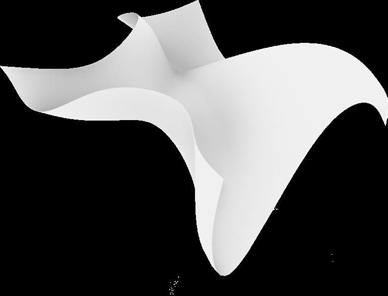
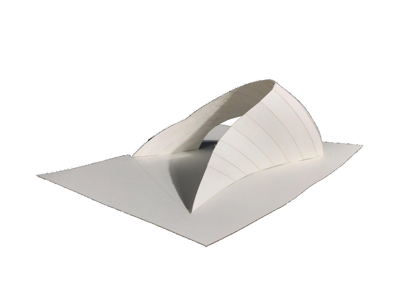
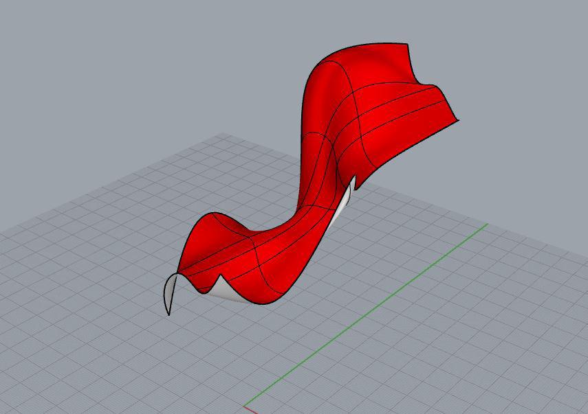
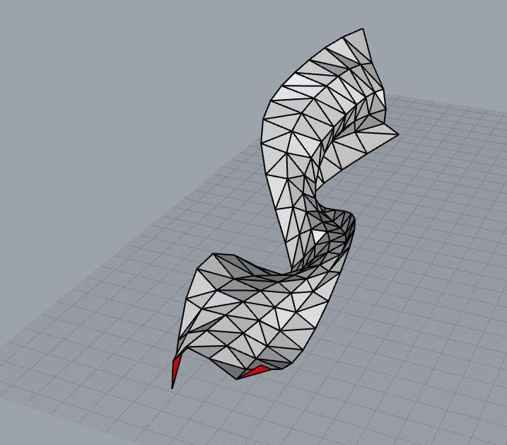
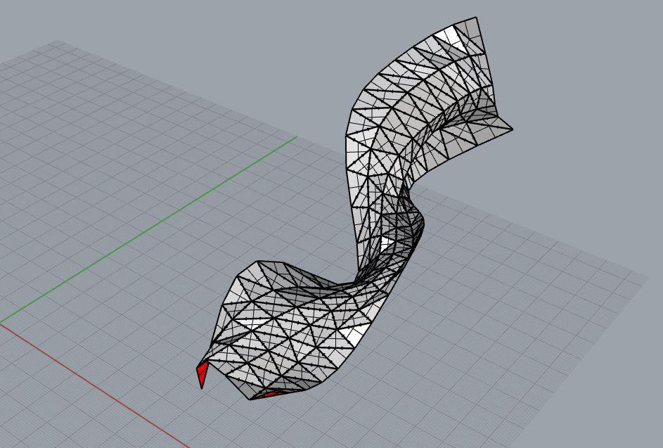
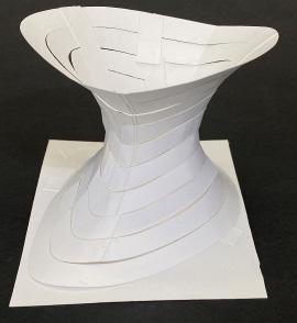
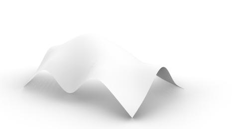
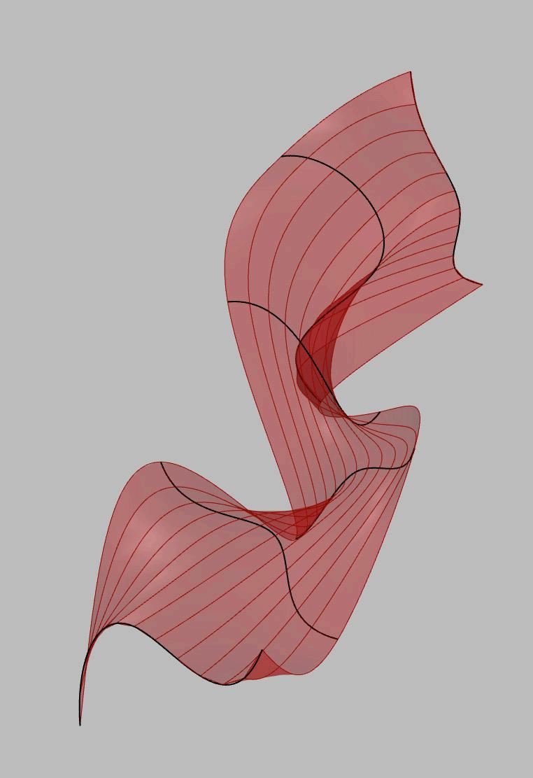
Various Rhino commands were used for surface generation. The most successful were the ones that created the most double curvature while staying true to the edge curves, such as NetworkSrf.
Loft Sweep2
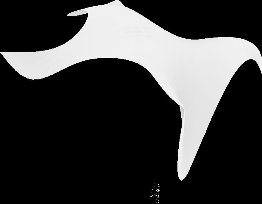
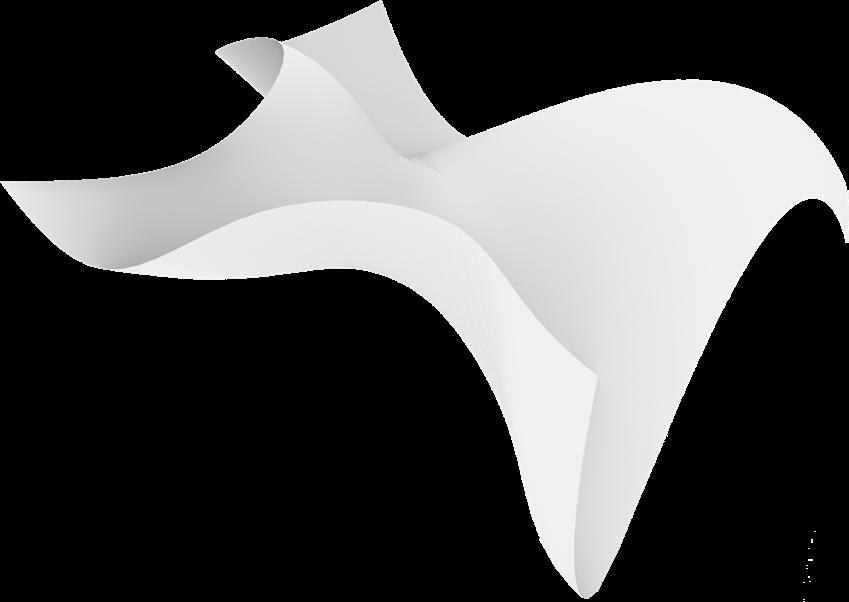
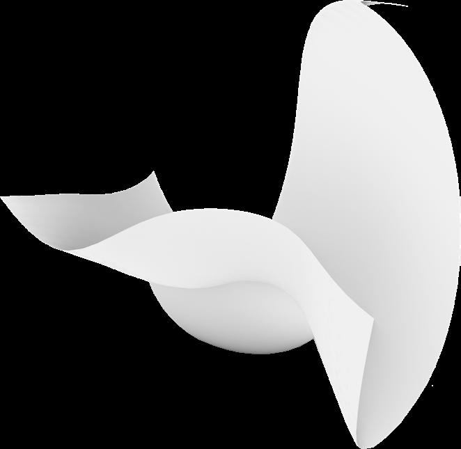
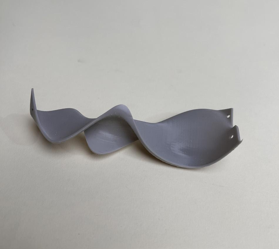
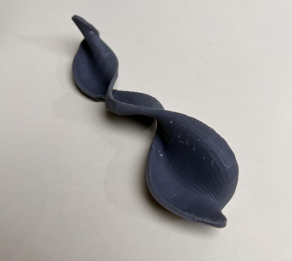
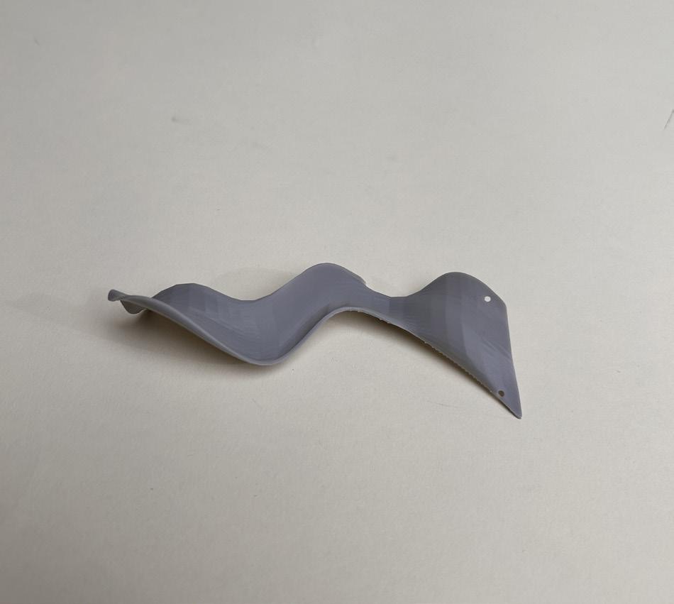
Methods and Commands for Generating a Double Curved Surface: Bend, Twist, SubD
Various Rhino commands were used for surface generation. The most successful were the ones that created the most double curvature while staying true to the edge curves, such as NetworkSrf.
Bend
Twist
SubD Loft
SubD Sweep2
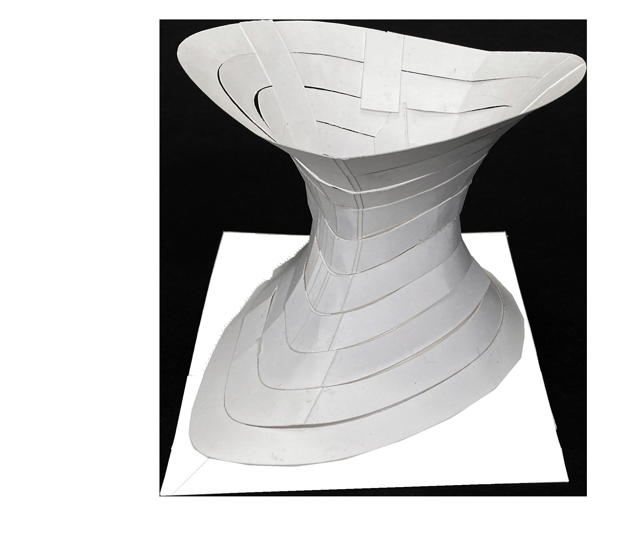
Methods for Subdivision:
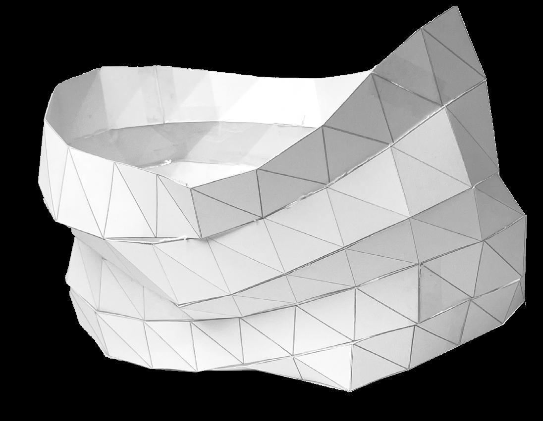
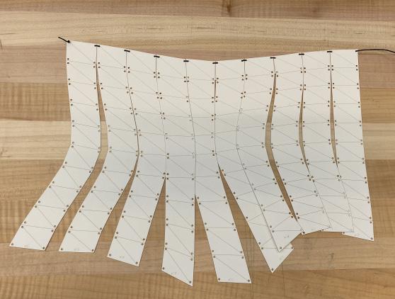
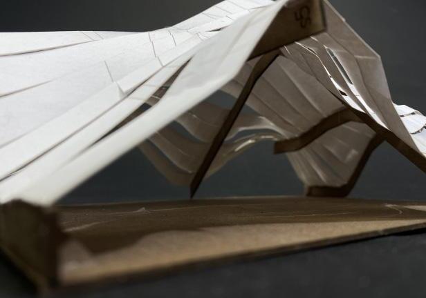
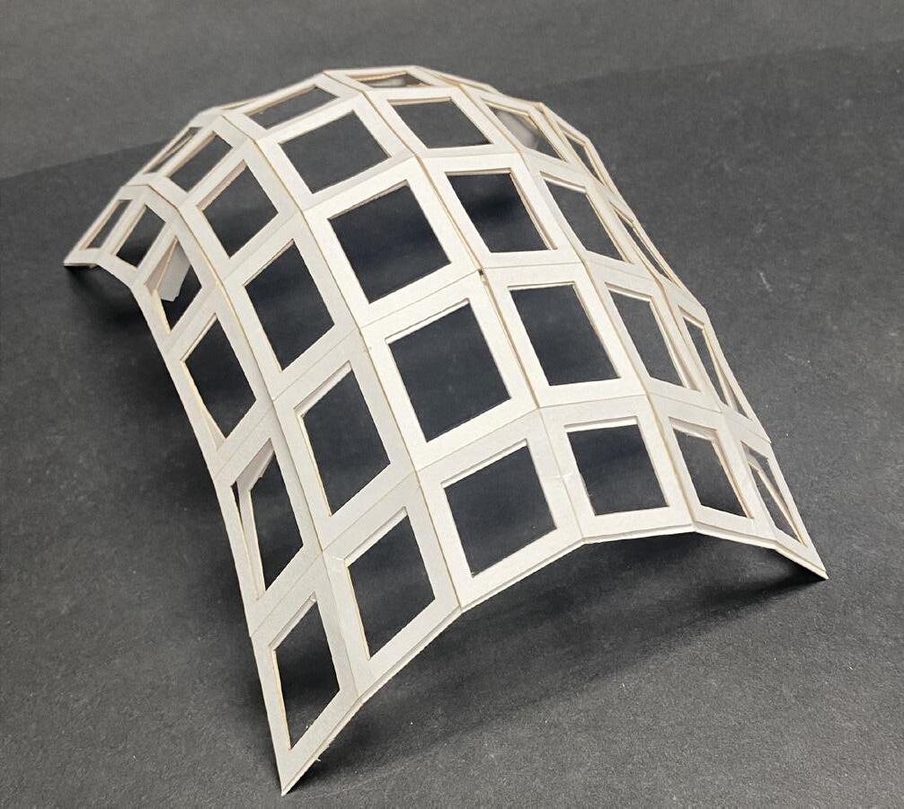
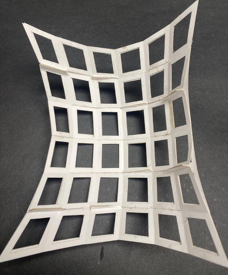
UV Strips
-Sweep2
-Made by extracting IsoCurves from a Nurbs Surface
- Tolerance
-Higher discretization usually creates more error.
-High control of order
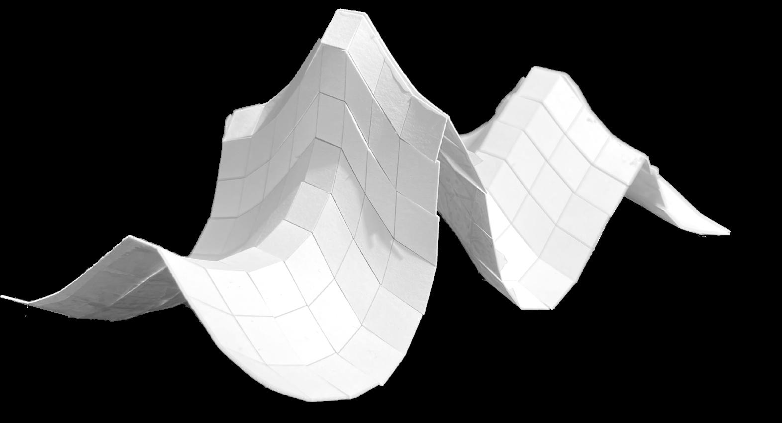
Methods for Subdivision:
Mesh
-Mesh, Mesh Reduction
-Divides a surface into planar parts
- Higher discretization with more subdivisions
-Lack of control of order
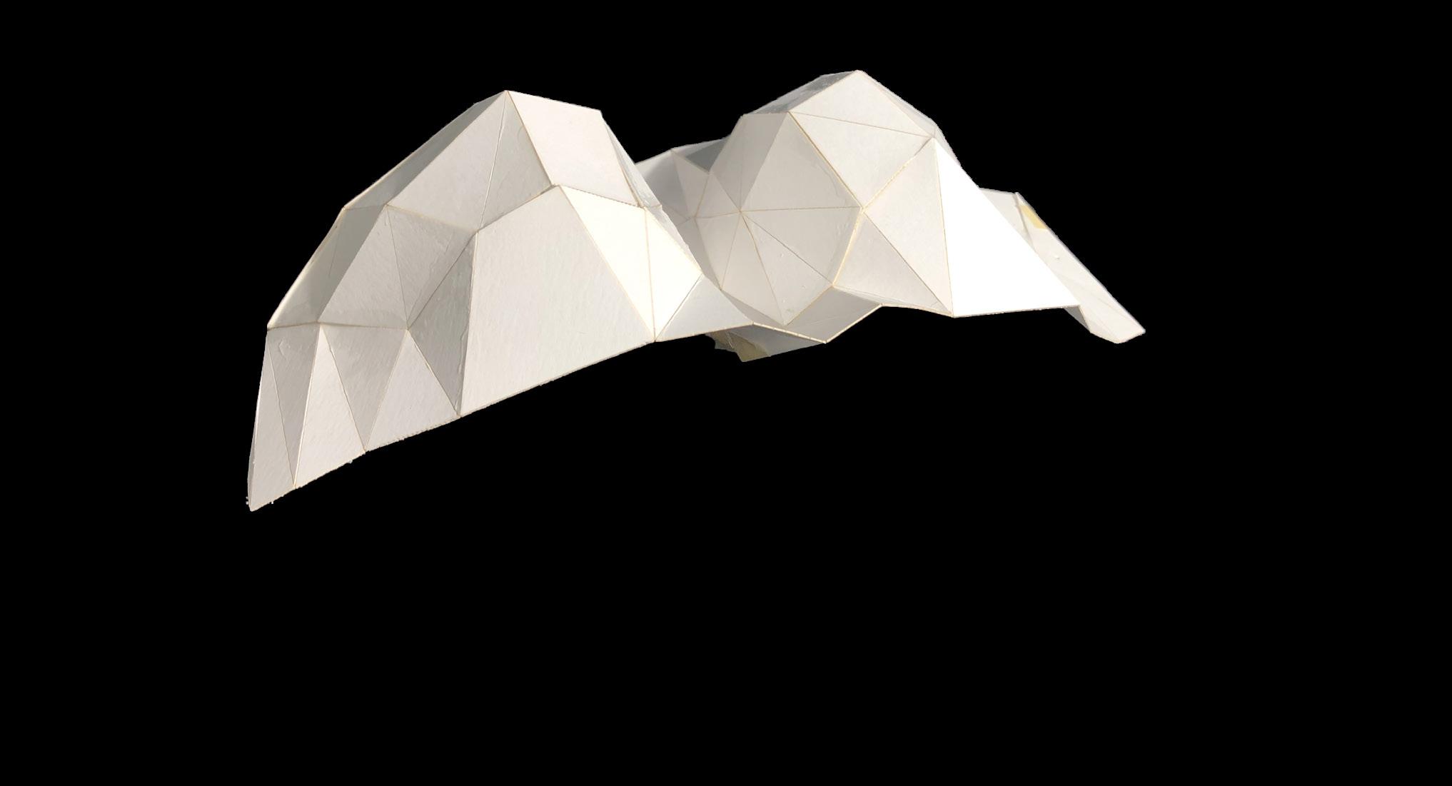
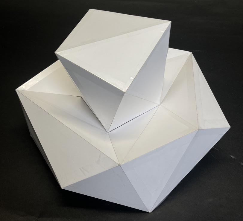
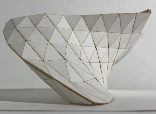
Methods for Subdivision:
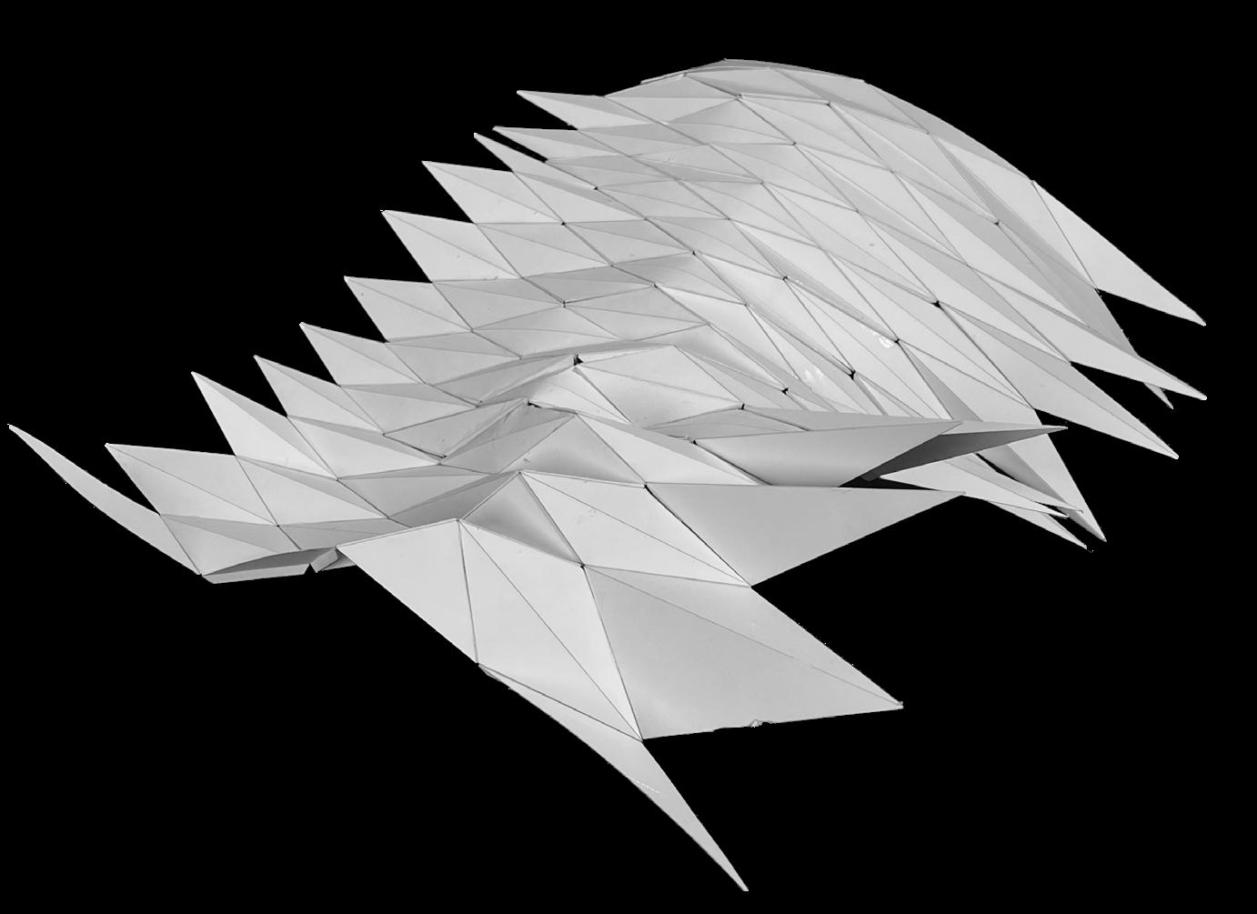
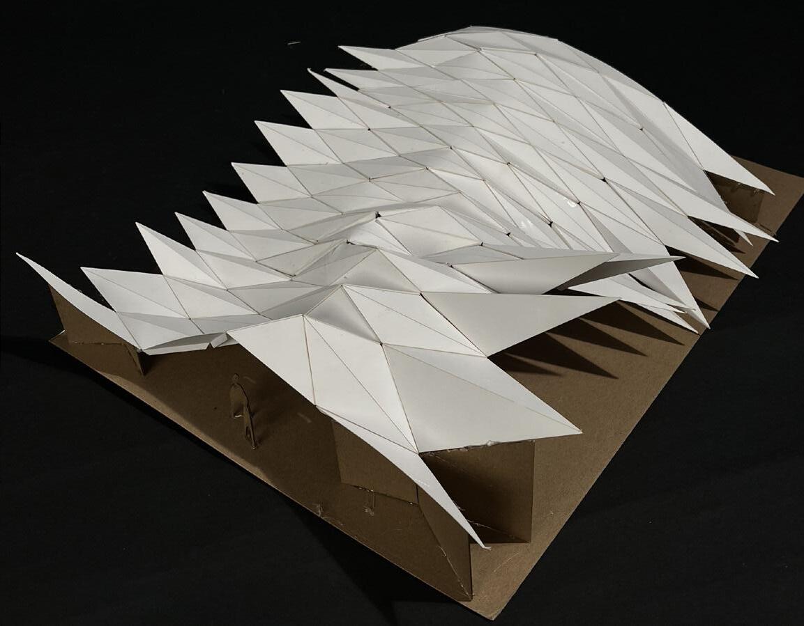
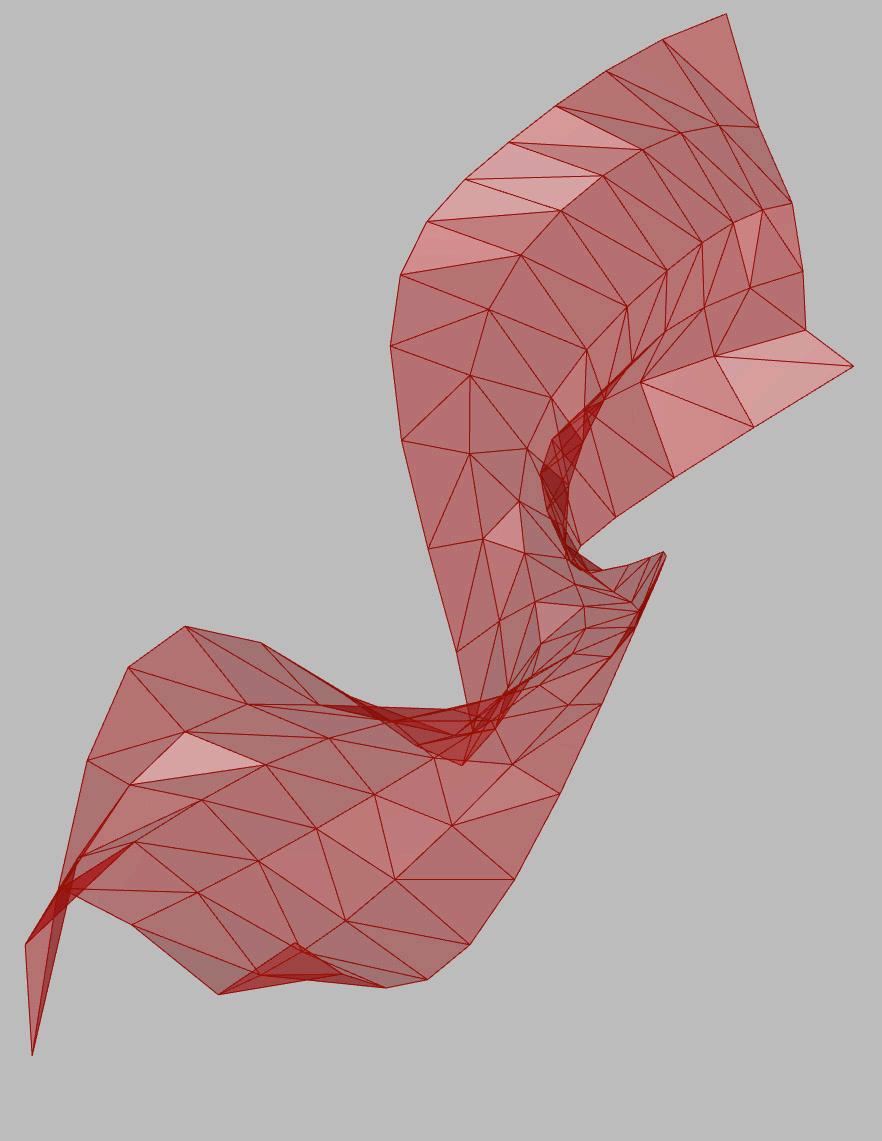
Triangulation (mesh or manually)
-Triangulate Nonplanar Quads or can be done manually
-All pieces are flat
-More control of order
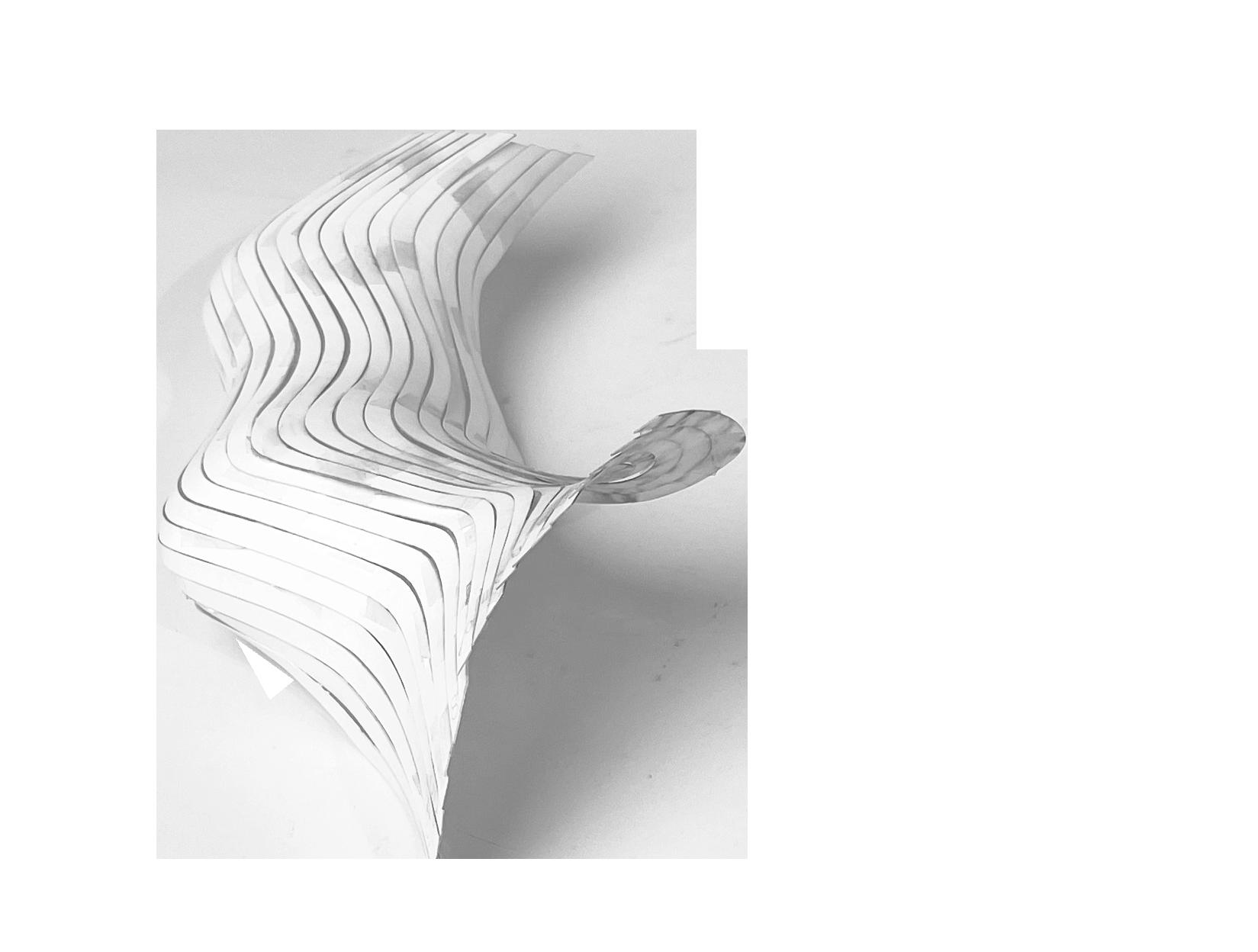
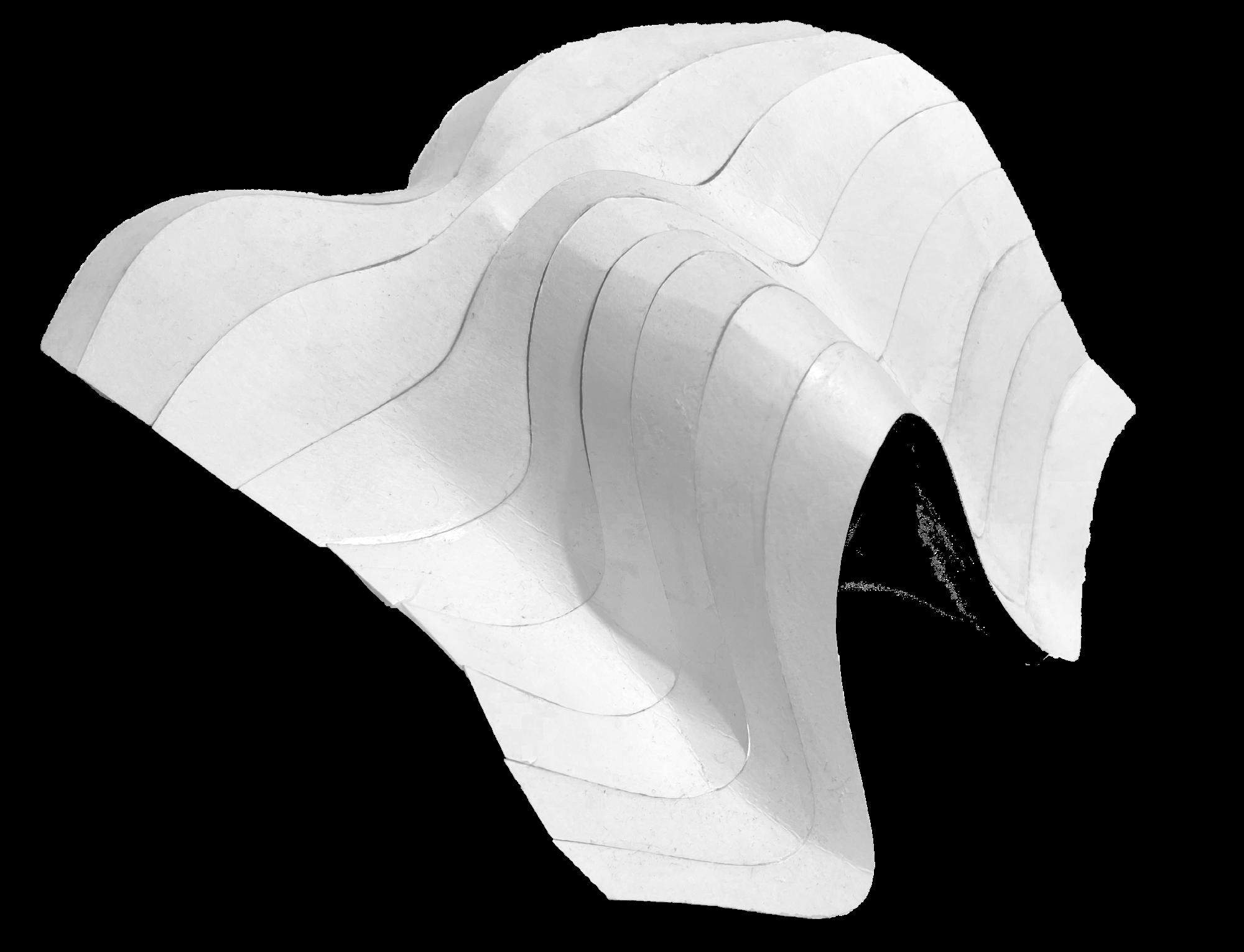
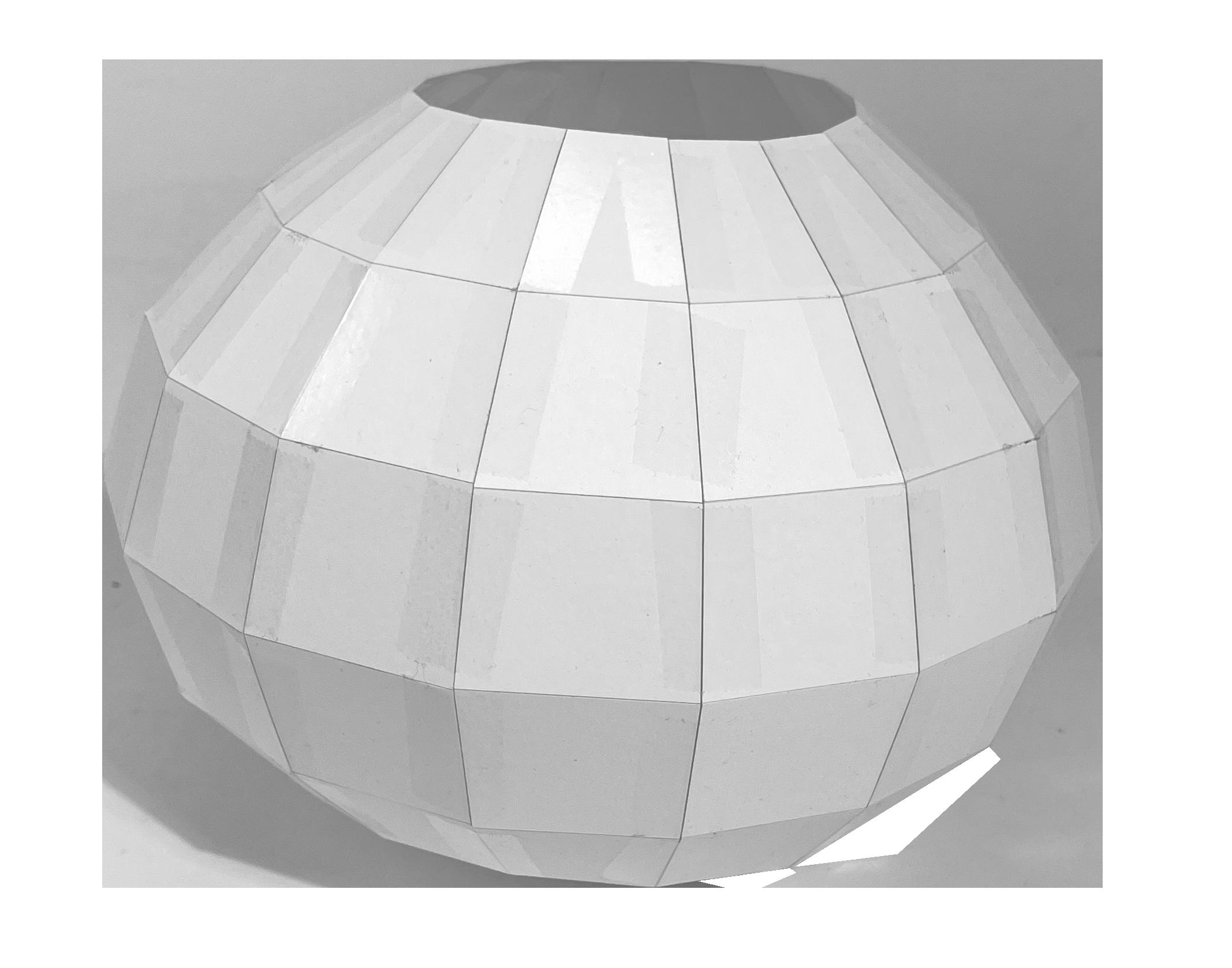
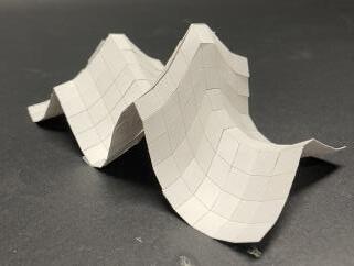
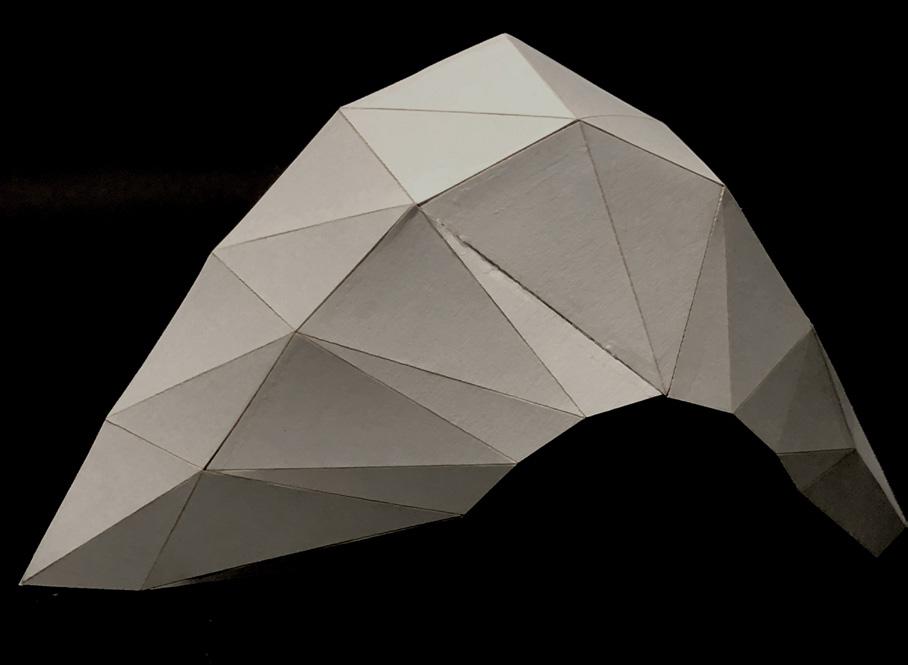
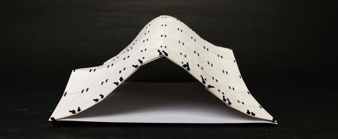
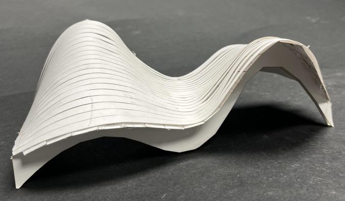
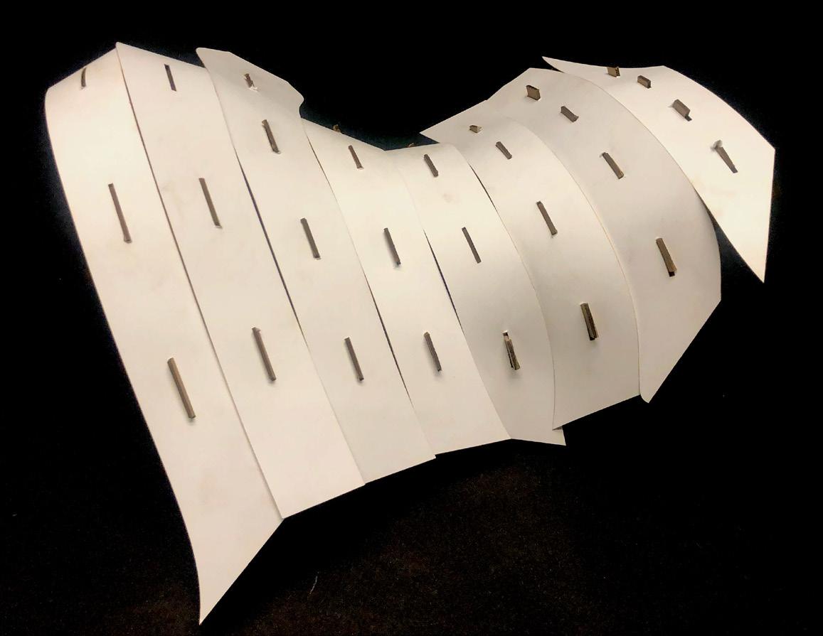
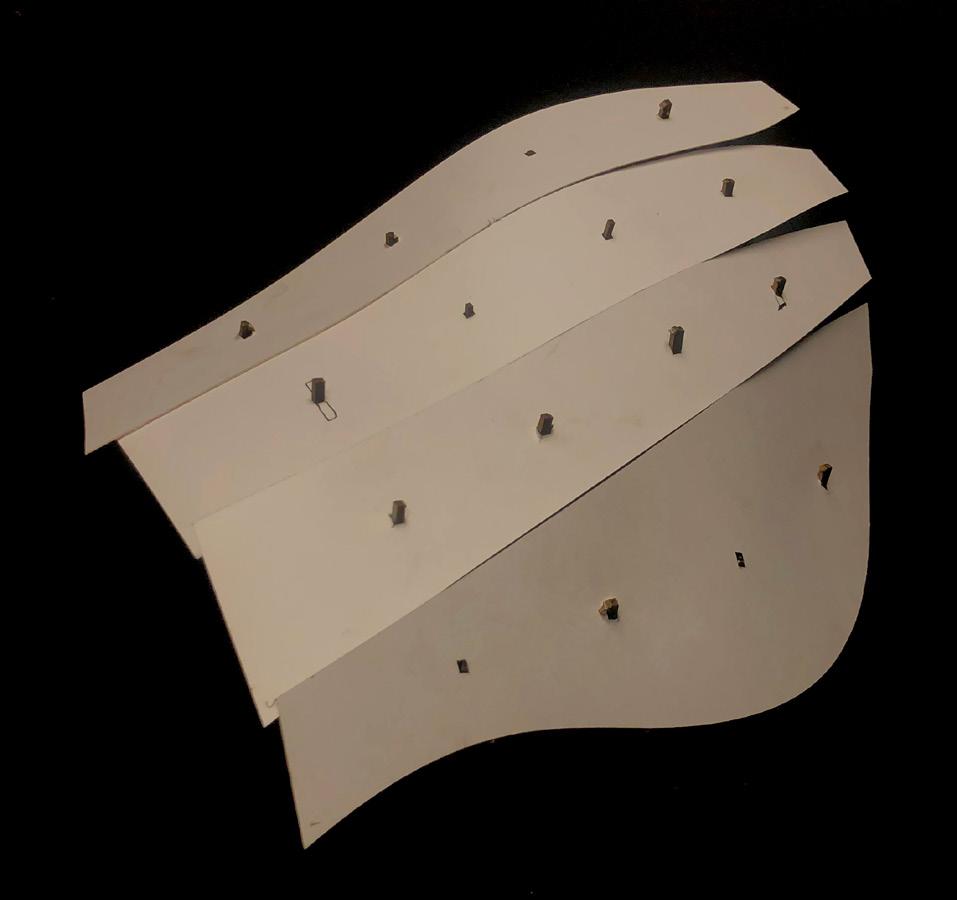
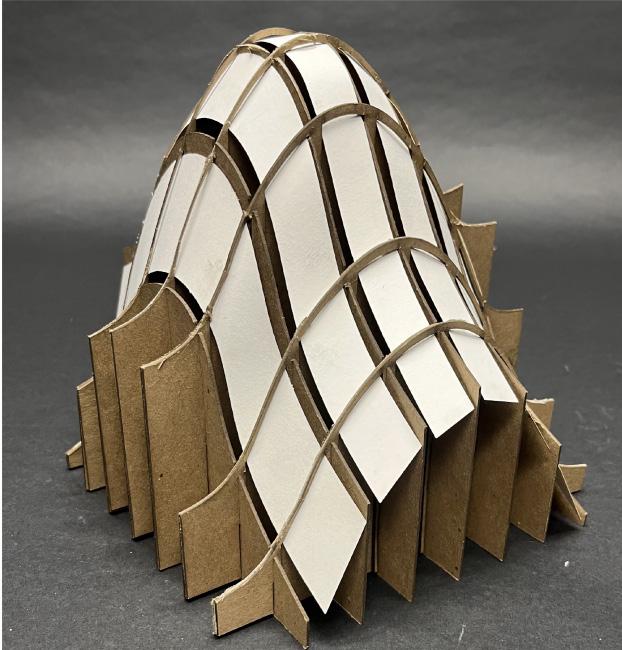
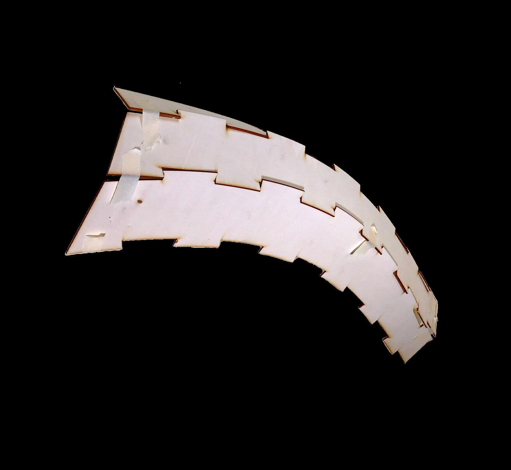
Unrolling Double Curved Surfaces
Rhino does not unroll double curved surfaces without any distortion.
Breaking a surface into less double curved strips, or small flat pieces (below)
We were able to unroll our panels with no distortion. This was not the case early in the semester
Organize these pieces onto sheets for the laser bed.
- you might wanna use the grouped surfaces to make the files rather than the duped edges so that we can keep the lables tied to them for as long as possible.
Then plot a stencil (with the material size edge boarder indicating the laser bed) to place the already CNC'd pieces on in the laser bed in exact positions. (We can just put a small piece of tape
Tolerance
Tolerance is the amount of errors allowed within a project. Some examples would be the distance between panels when assembed.
When unrolling, tolerance can allow us to be consistent with the amount of distortion that occurs.
Joinery Methods:
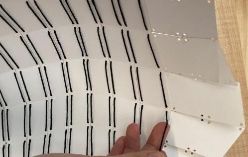
UV Strips with Glue and/or Tape
Joinery Methods:
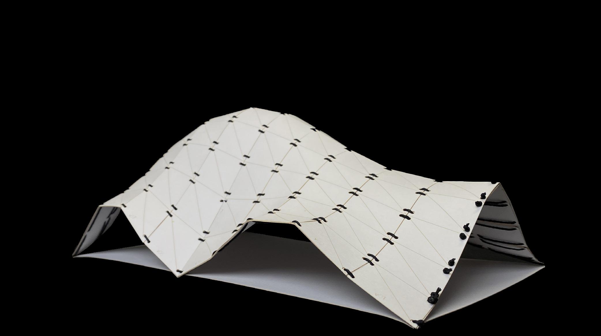
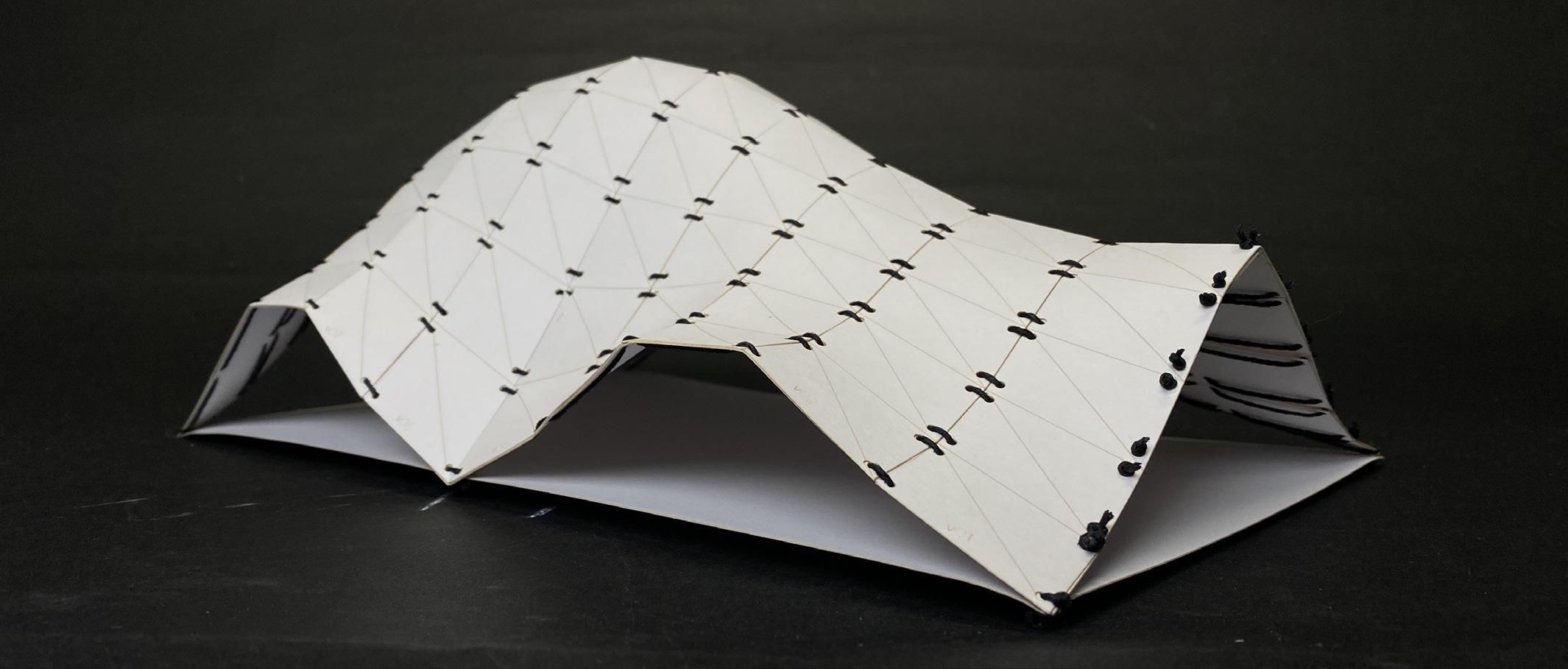
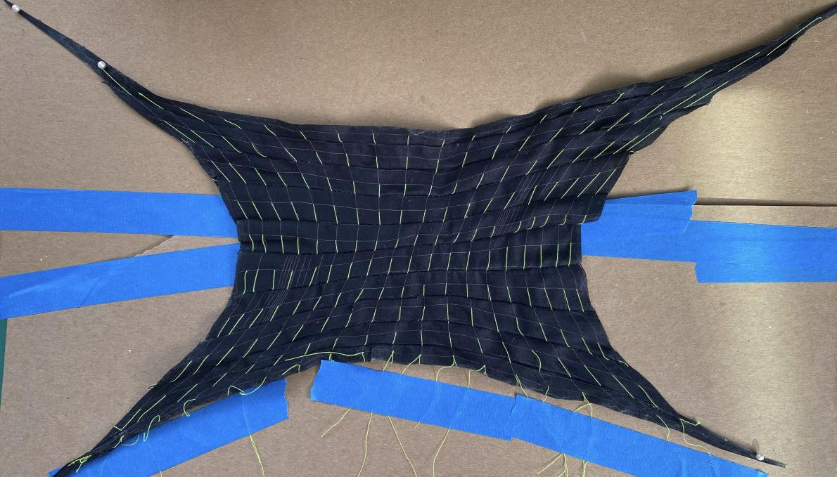
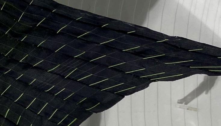
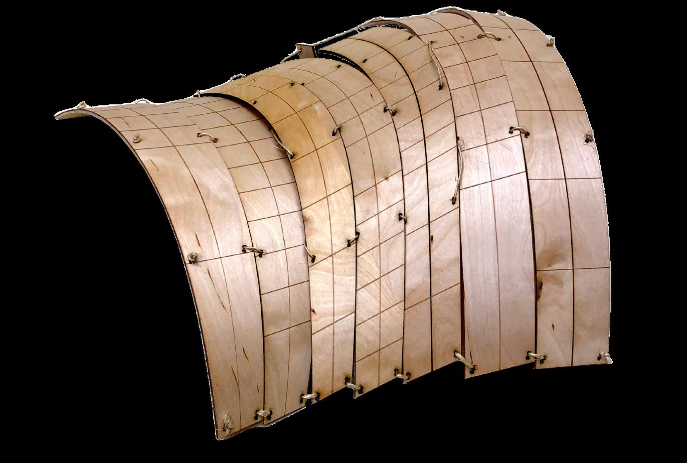
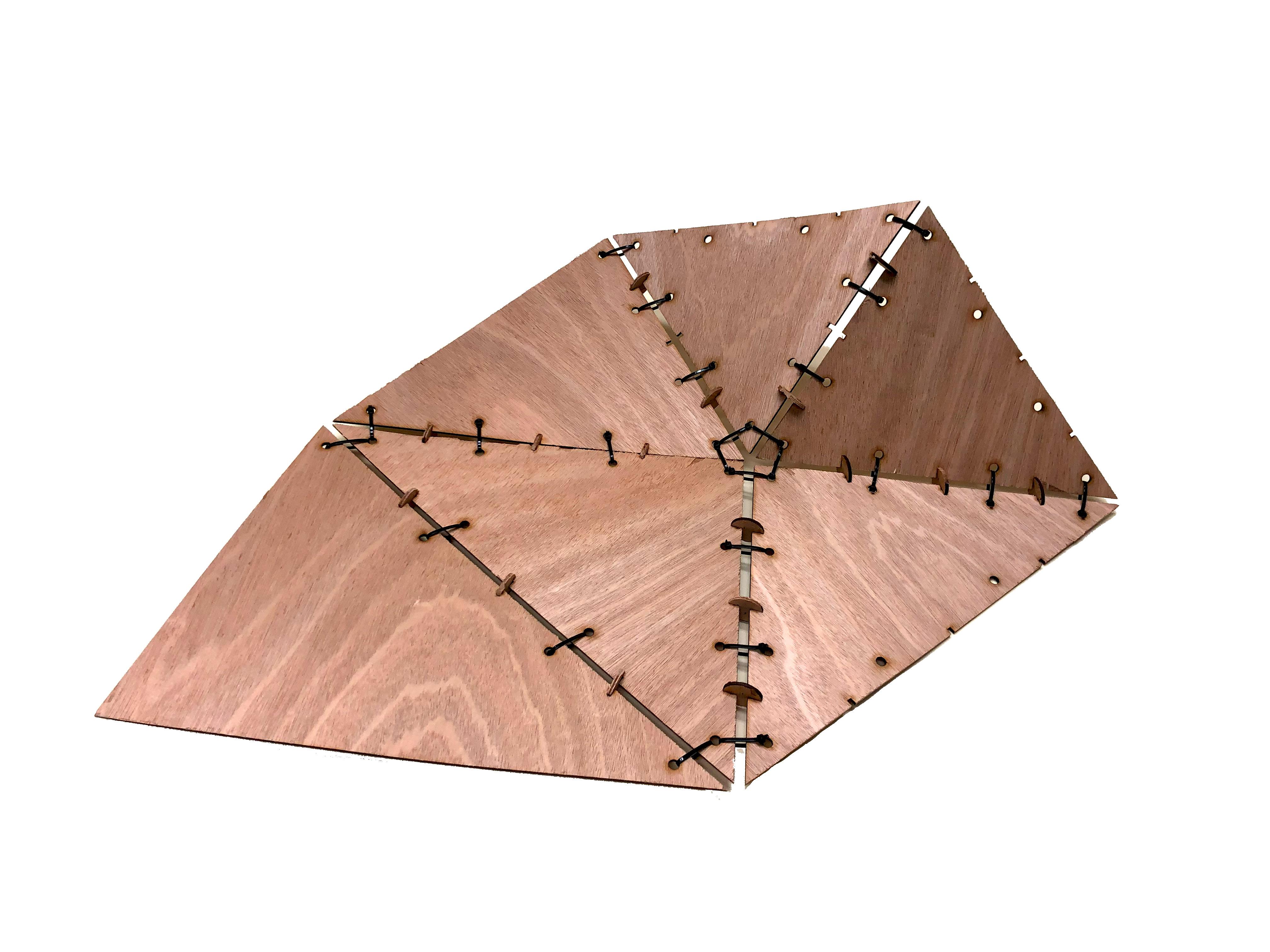
Cross Lamination with Sewing
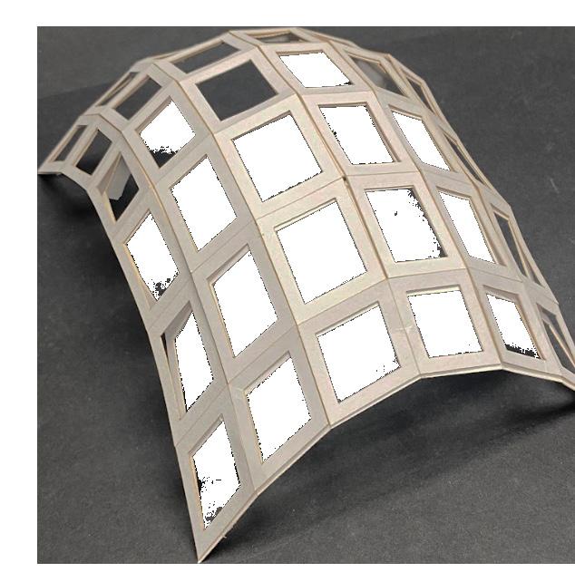
Joinery Methods: UV Strips with Structure
Joinery Methods:
Sewing Fabric/ Sewing Fabric with Structure
Joinery Methods:
UV Strips with Tabs and Structure
Joinery Methods: Other Methods
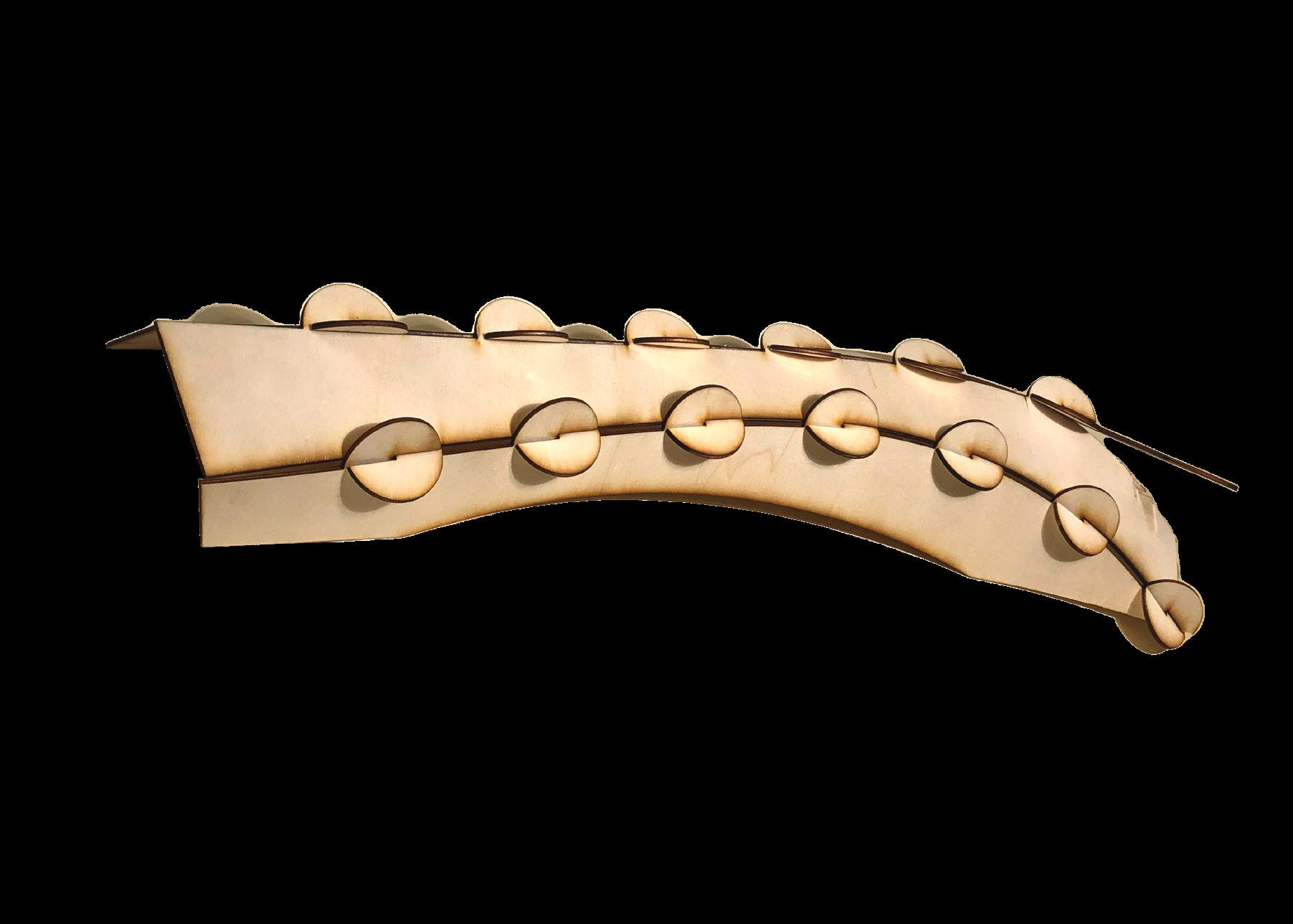
Strips with Holes
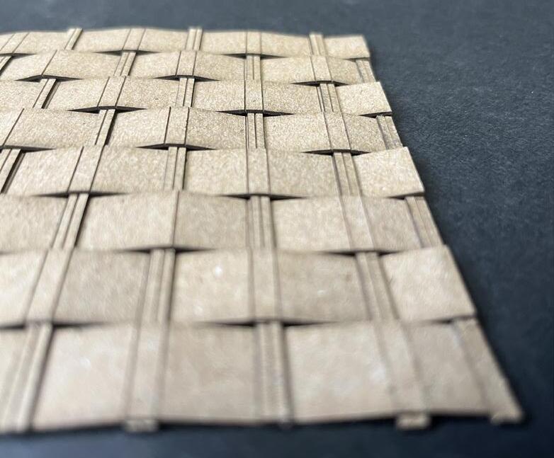
Waffle Structure with Strips
Cross Lamination with Tabs
Triangular Joinery
Cross Lamination
Grasshopper:
A parametric modeling tool that has the power to exponentially increase design efficiency.
definition
Used to:
-Generate surface iterations
-Populate curves with tabs and other shapes
-Divide surfaces into UV curves
-Populate surfaces with apertures at adjustable radii
Later it was used to:
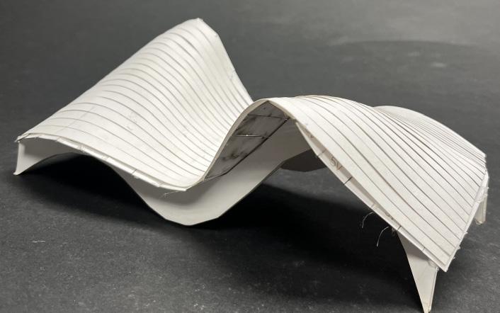
-Change any Nurbs surface to an adjustable number of developable strips (using Sweep2)
-Change any Nurbs surface to the one you see in the hallway (see definition later in the presentation)
definition
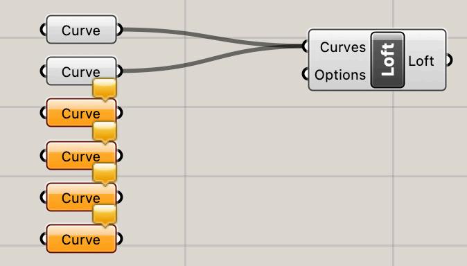
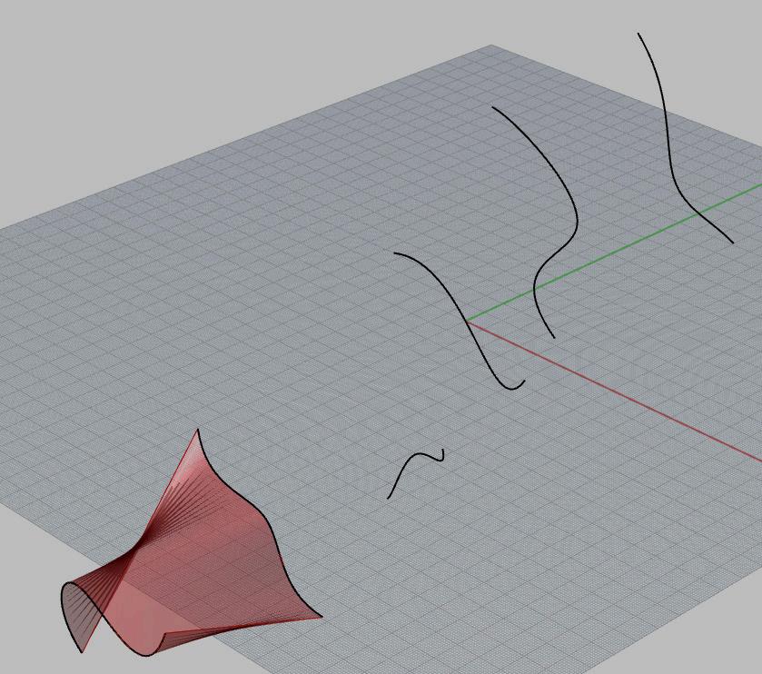
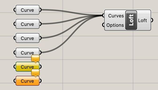
LOFT
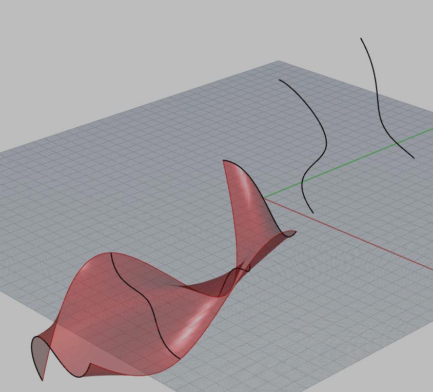
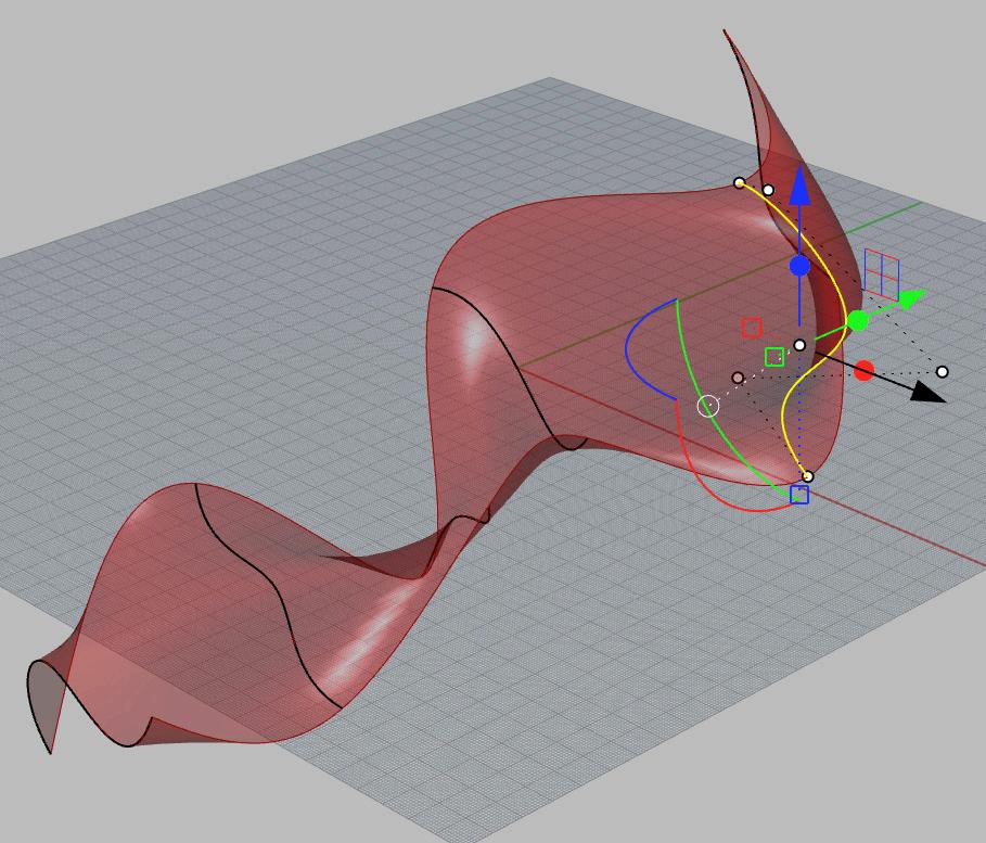
As the curves are added to the GH componant (above) and as curve positions in Rhino change (right) GH updates the surface live
Grasshopper
Grasshopper
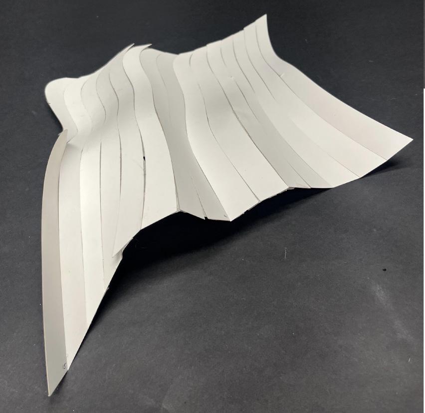
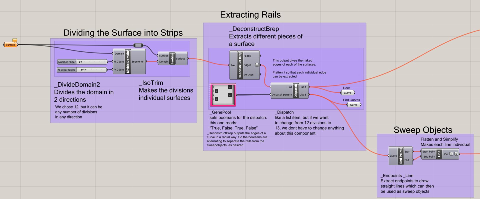
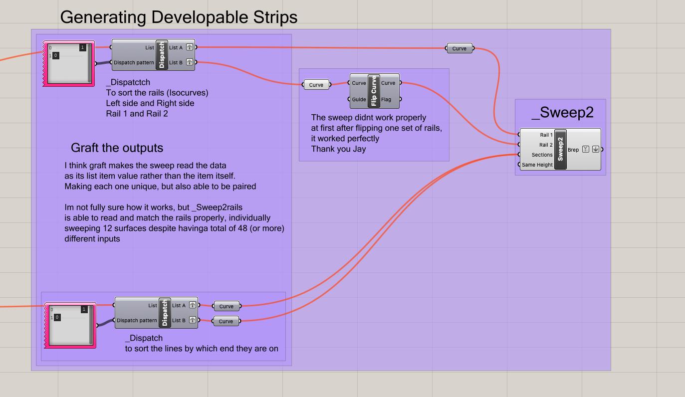
Grasshopper: Developable Strips Definition
This allows the number of strips (subdivisions) to be adjustable
Dividng the surface into segments using IsoCurves
Separating
alternating curves
Drawing line segments in between curves to create sweep objects
Separating straight lines that are on opposite ends of the surface
Sweep2, rails are the IsoCurves, Sections are the straight lines
SWEEP2 Surface generated by this grasshopper definition
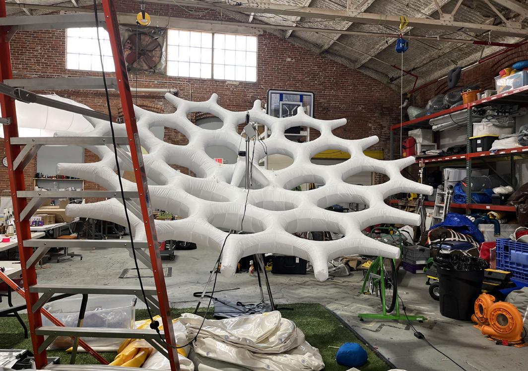
In the Field of Design
Feild Trips
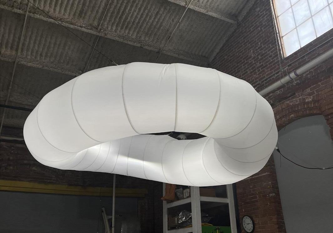
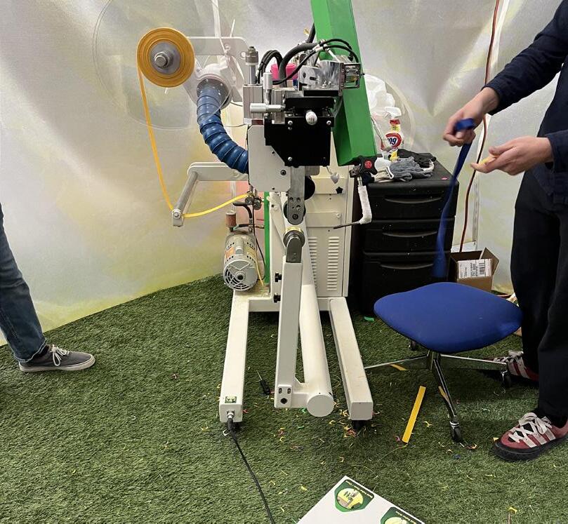
Pnuehaus, Rumford, Rhode Island
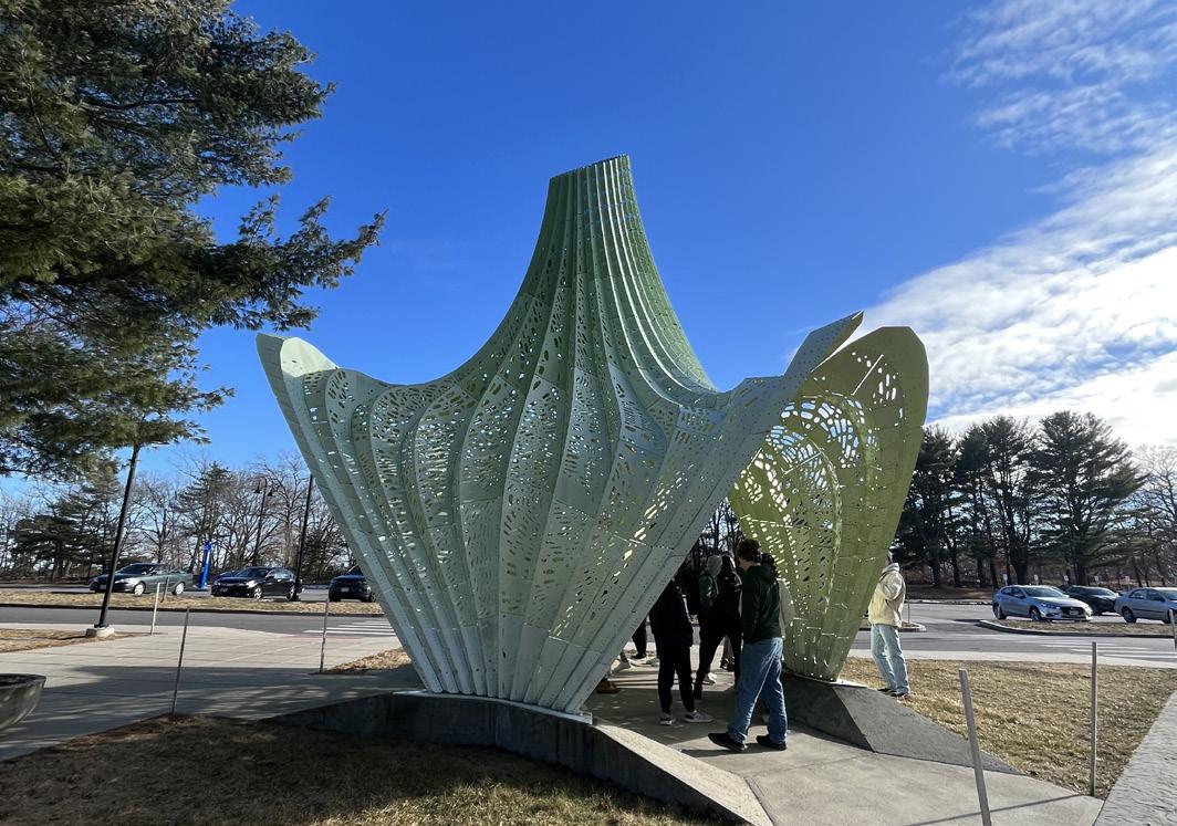
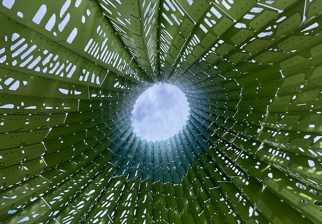
Hyperbole, Rhode Island College
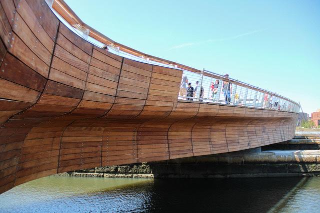
The Pedestrian Bridge, Providence, Rhode Island
Take-aways - Clear labeling system, method of joinery, simulation testing to ensure the success of the built model
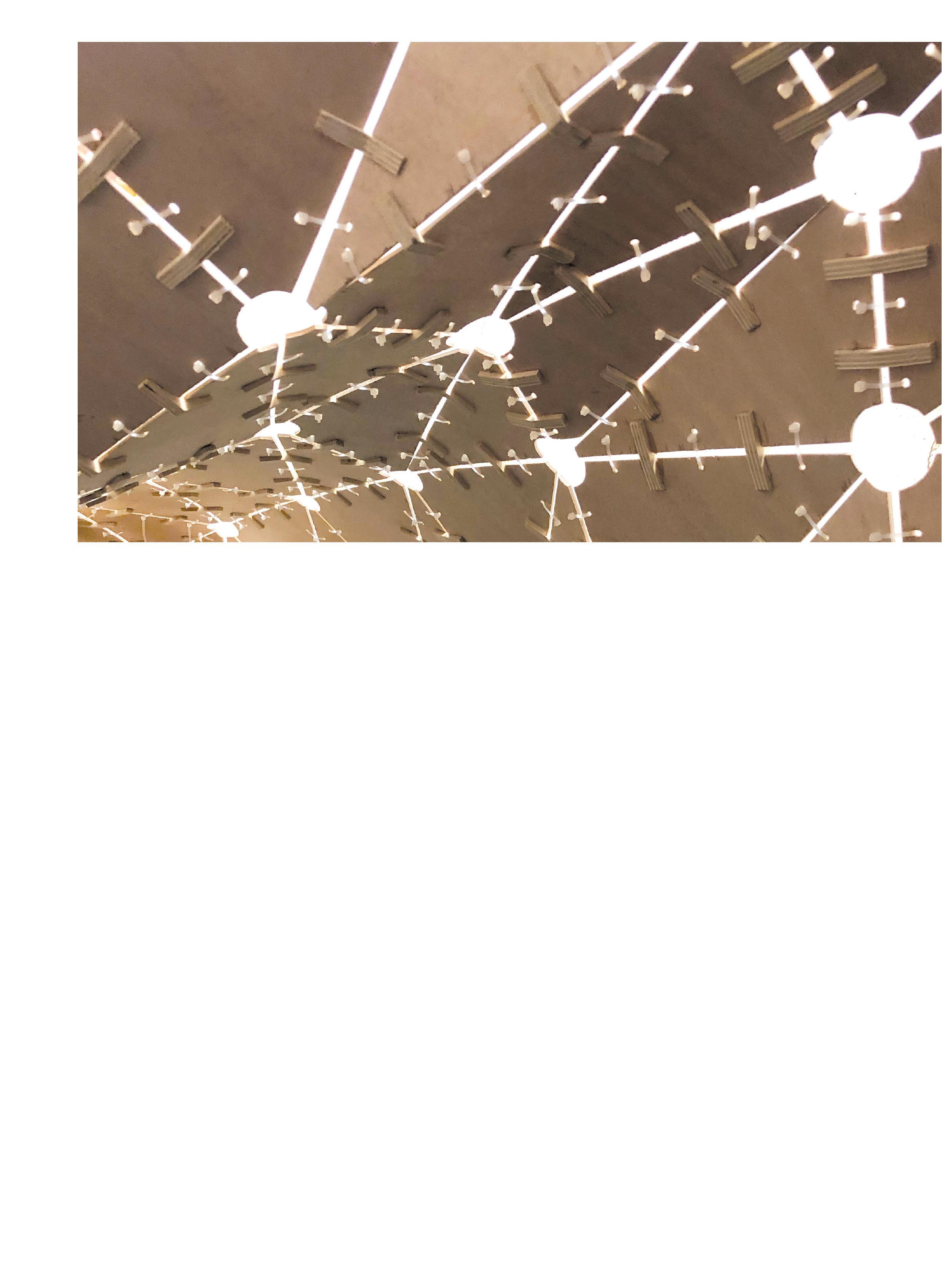
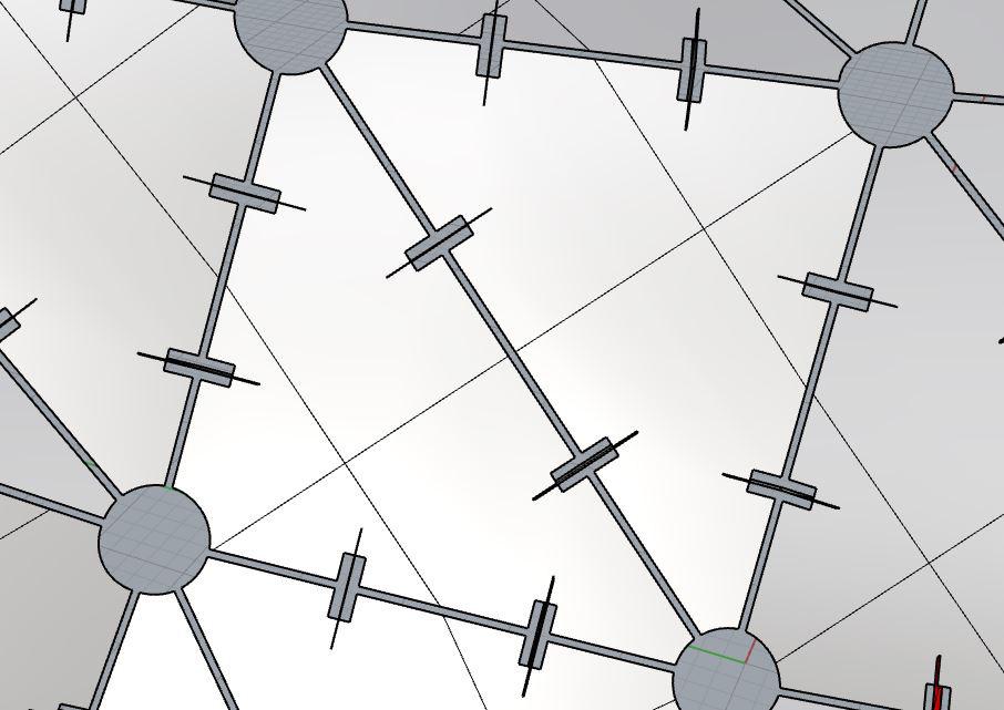
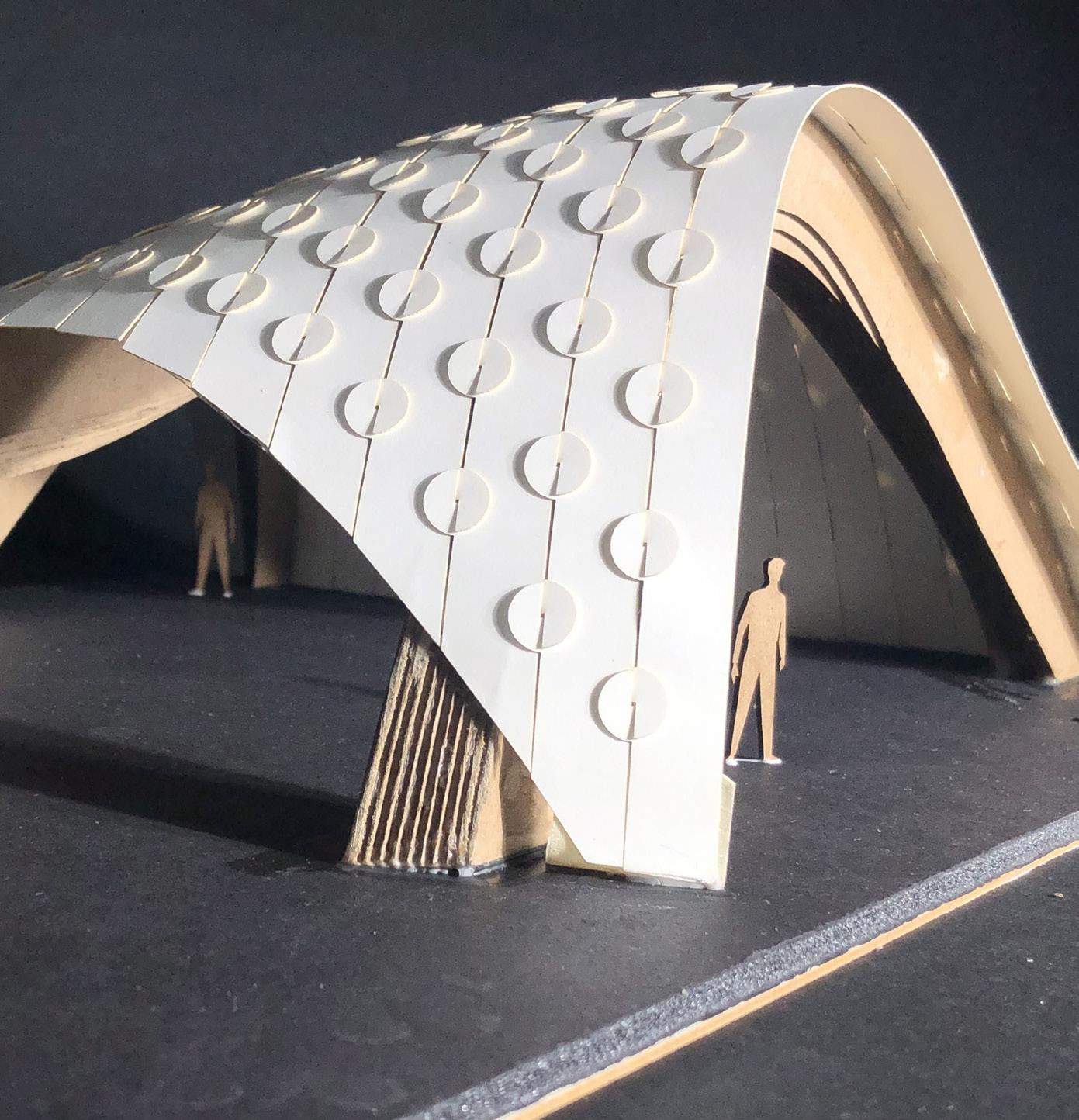
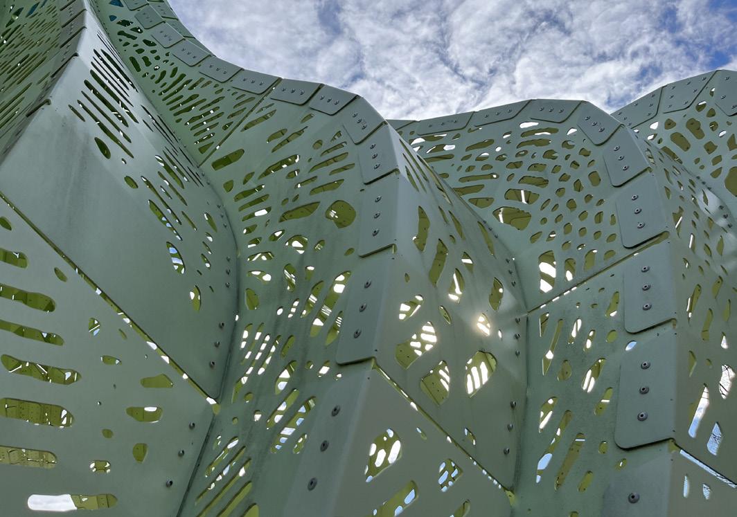
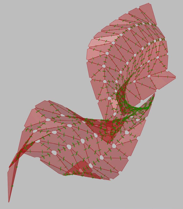
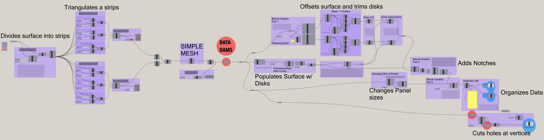
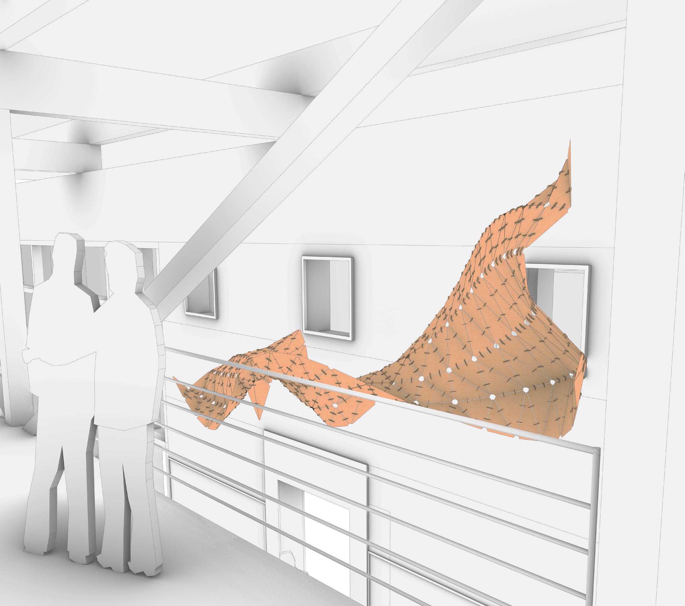
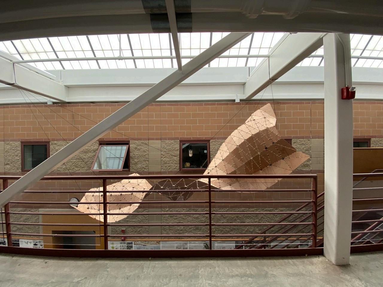
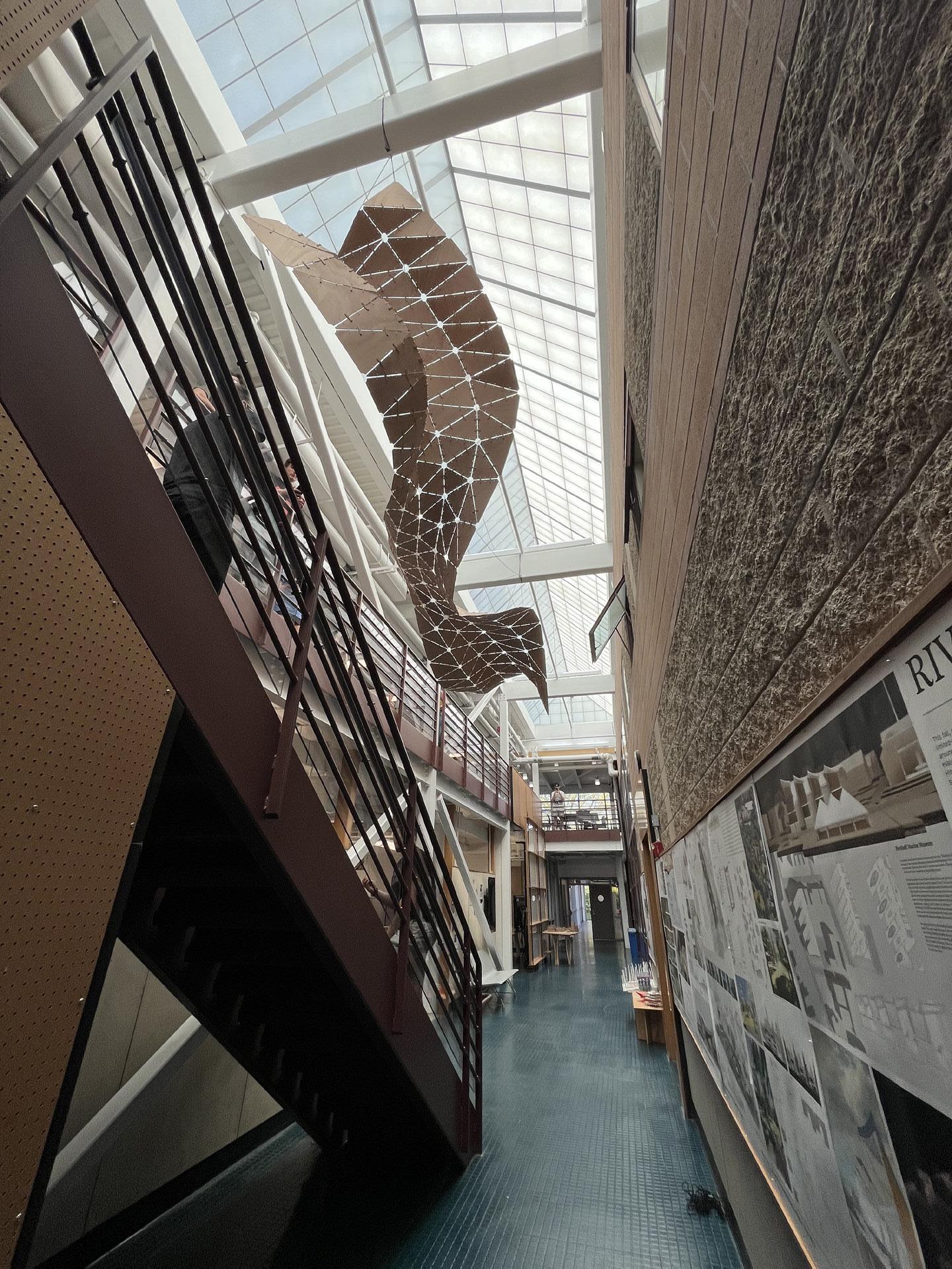
The Comprehensive Definition:
Grasshopper definition that transforms a nurbs surface into the final installation’s components
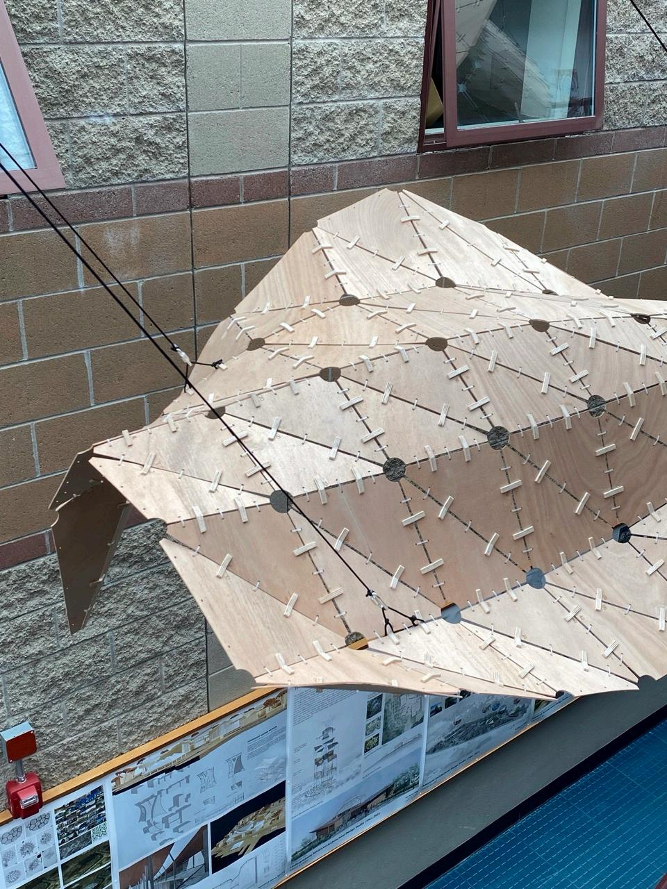
Surface Is divided into strips
The strips are triangulated, joined, and turned into a mesh
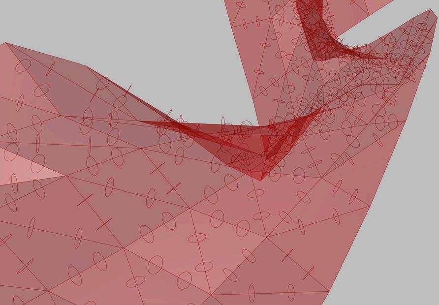
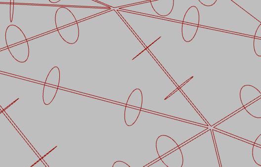
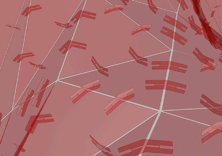
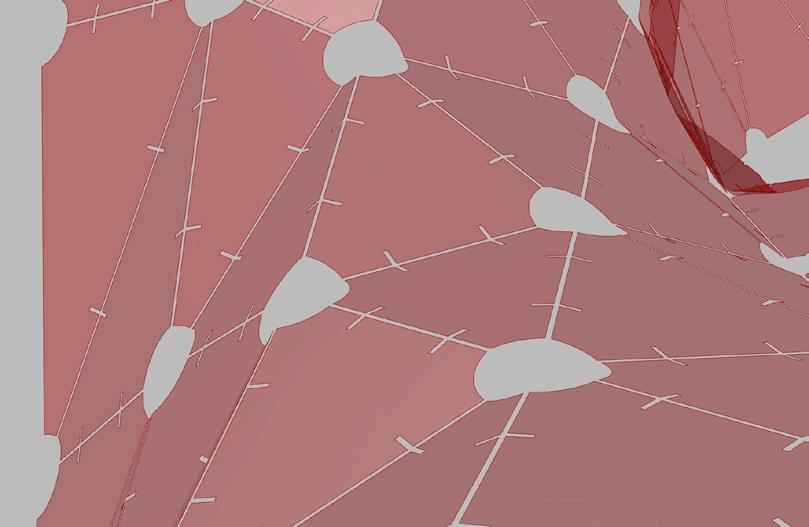
Disks populate the interior edges perpendicular to those curves
The mesh is offset and used as a trimming plane for the Disks
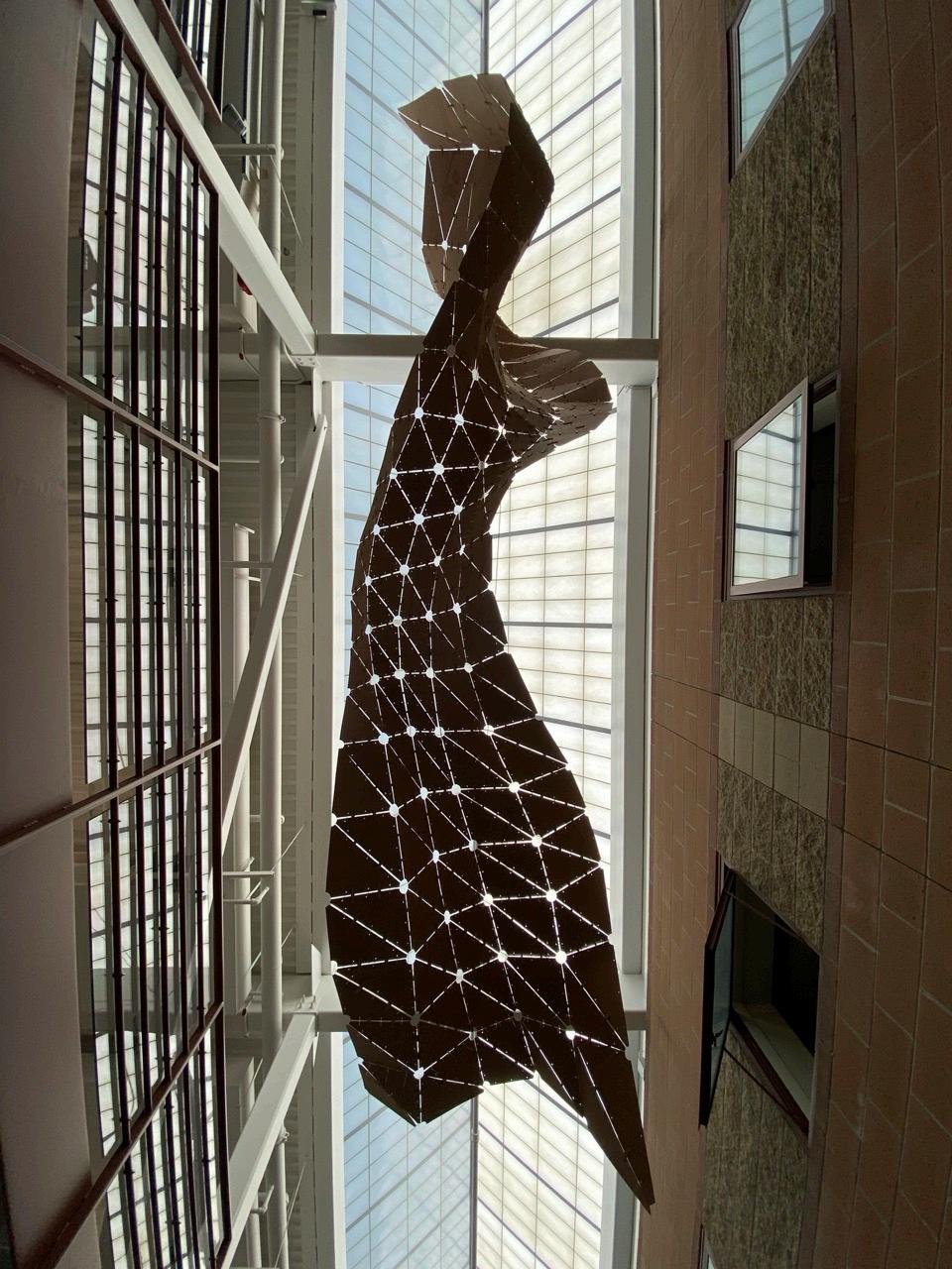
The triangles are scaled to a slightly smaller size, creating gaps inbetween each of them
Notches added at the intersection curves between each of the disks (now trimmed biscuits) and the panels
Holes trimmed at the vertex
Data Organized
The Comprehensive Definition:
The Design Team:
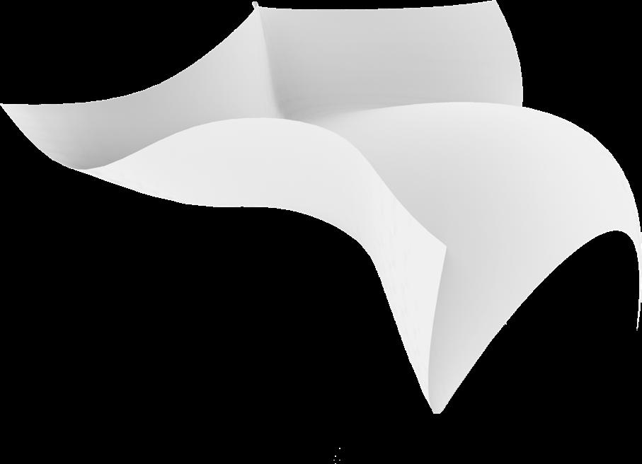
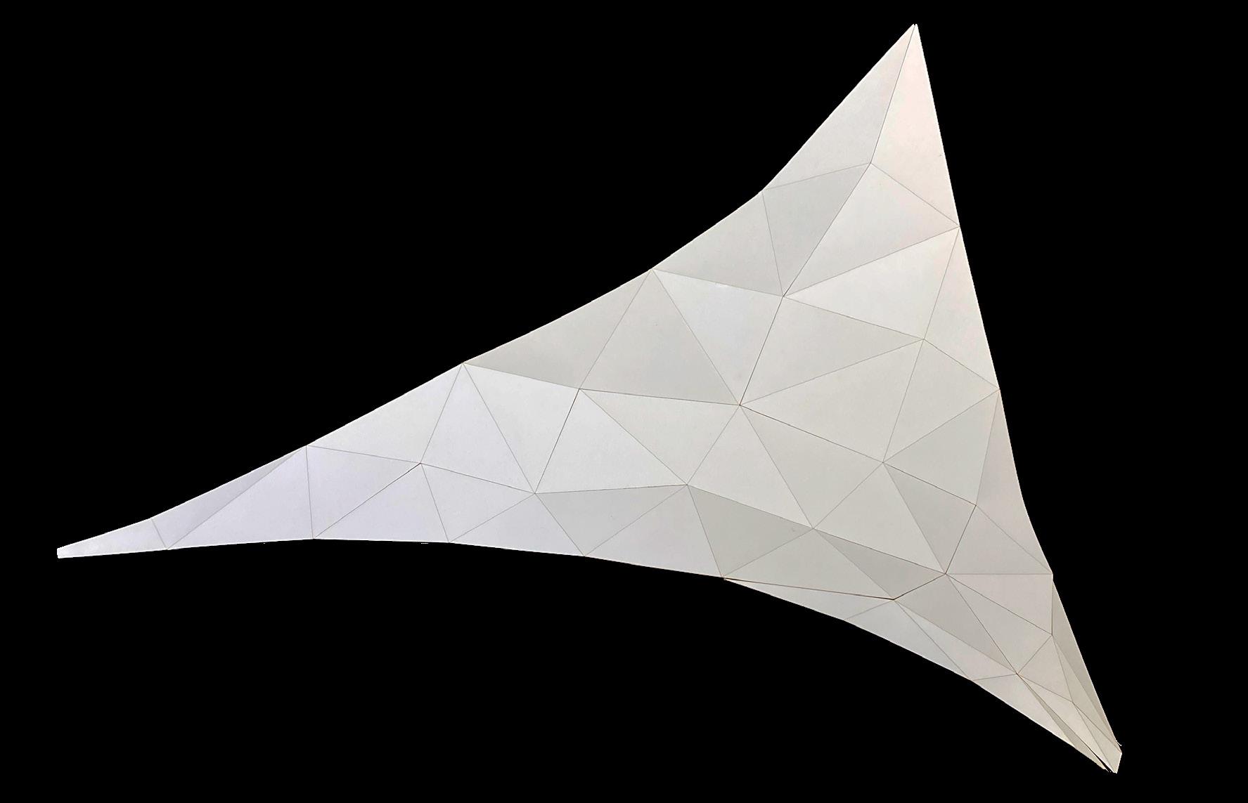
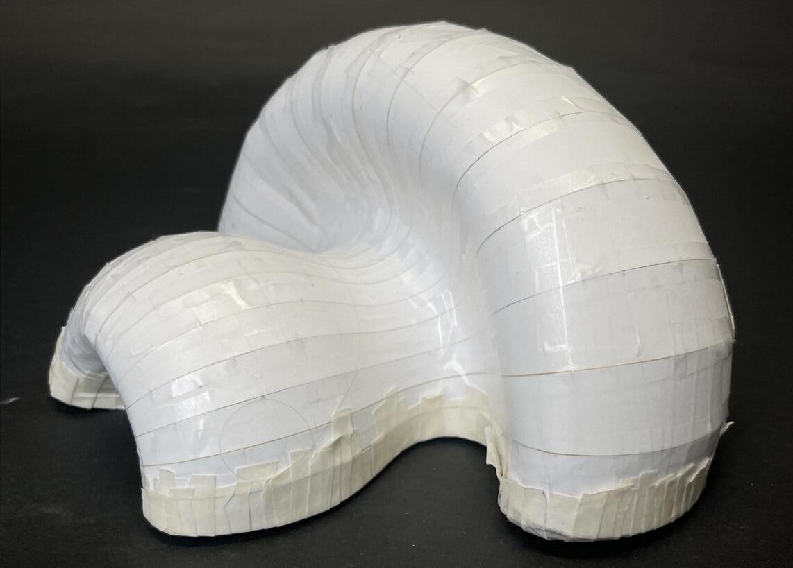
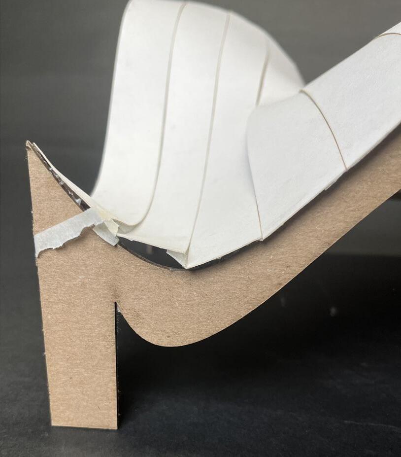
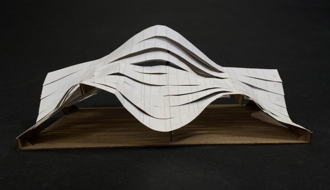
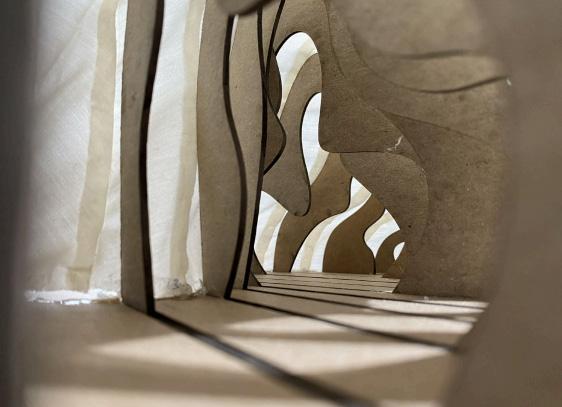
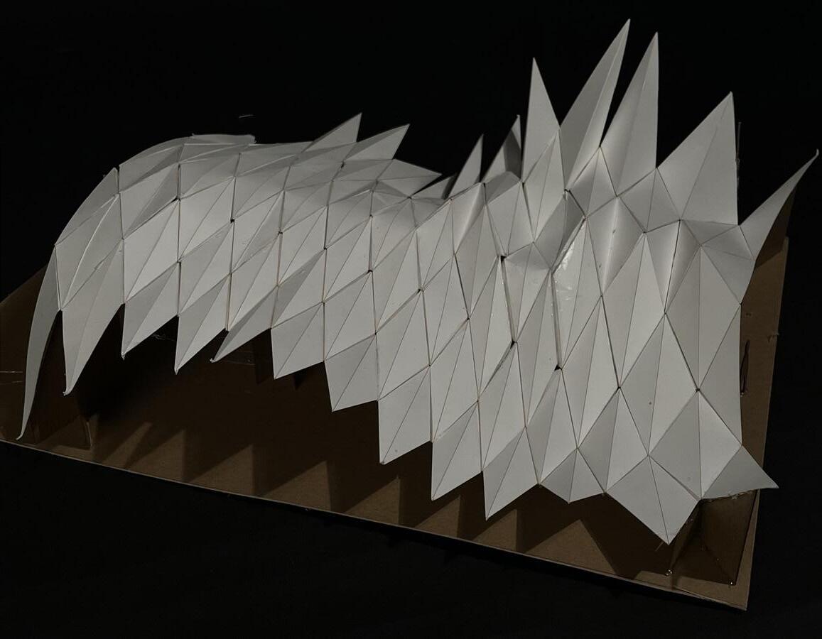
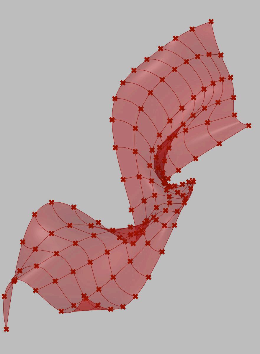
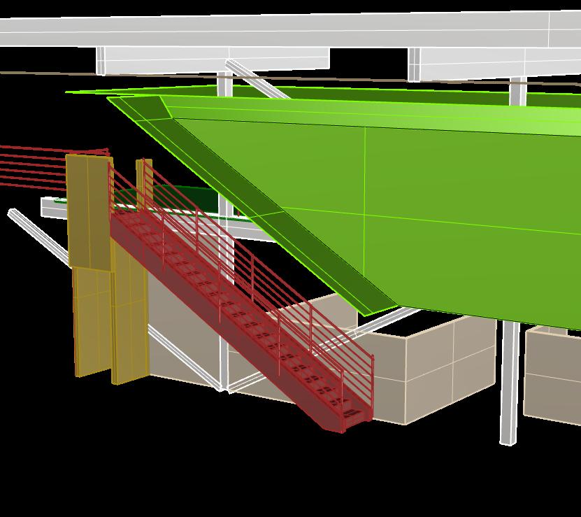
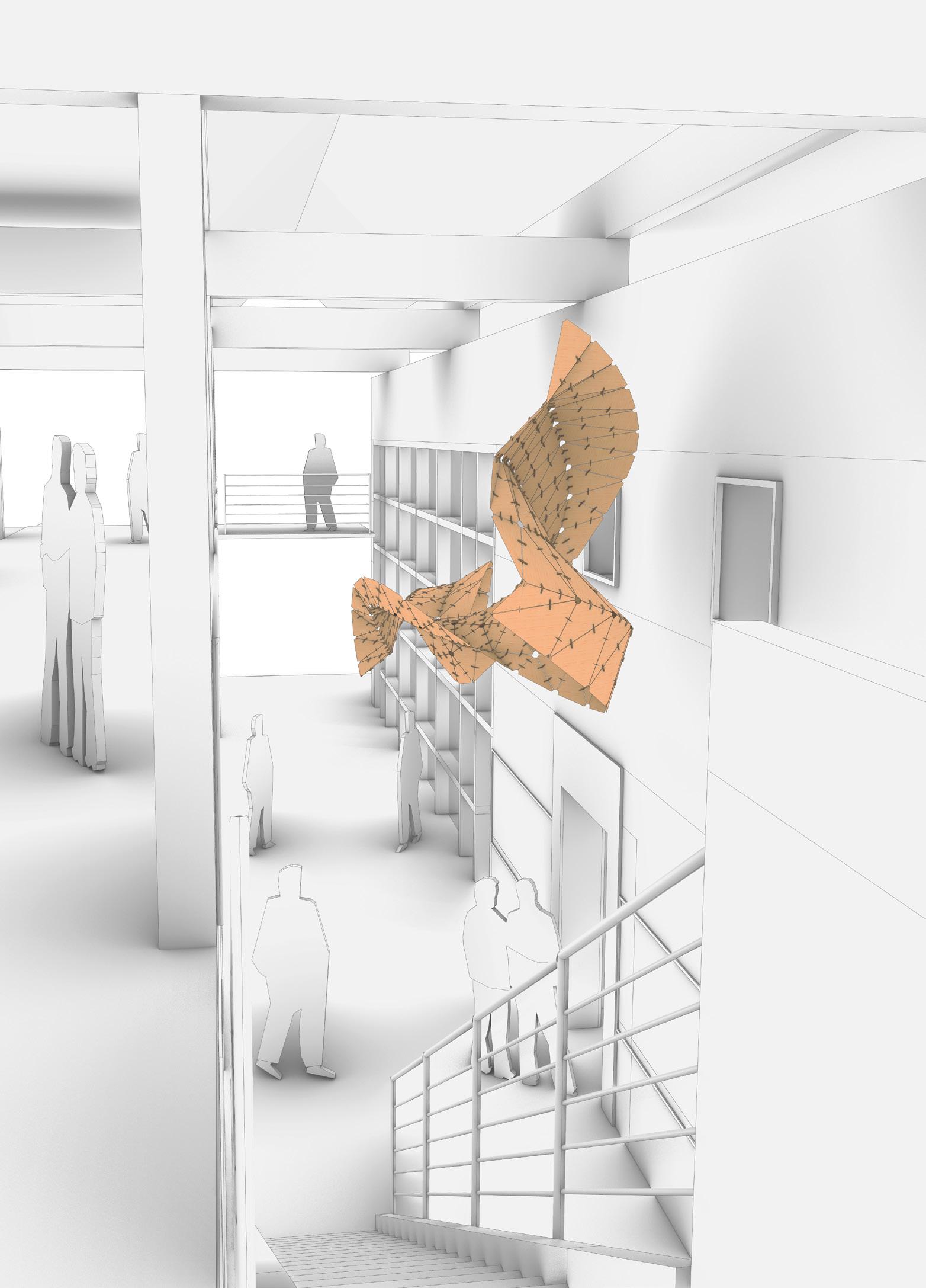
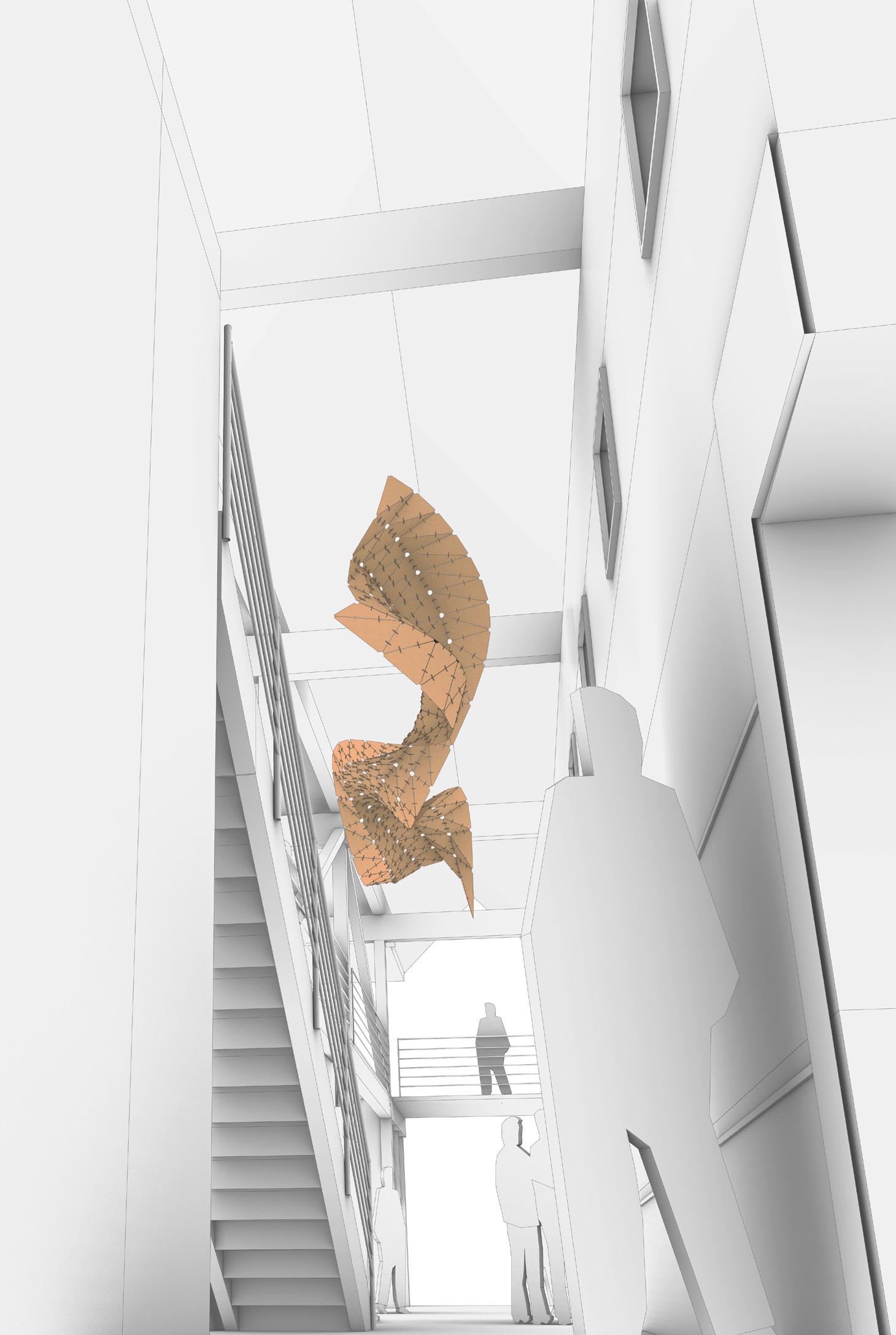
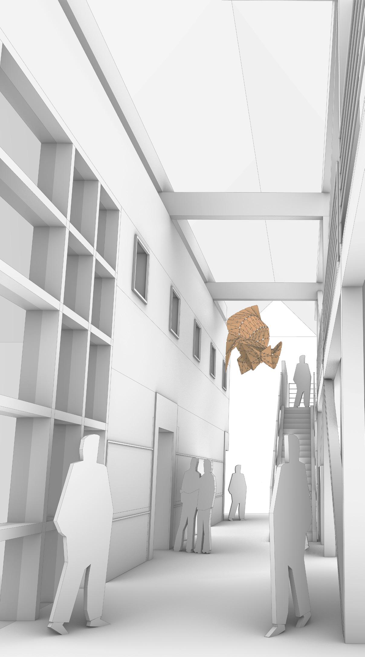
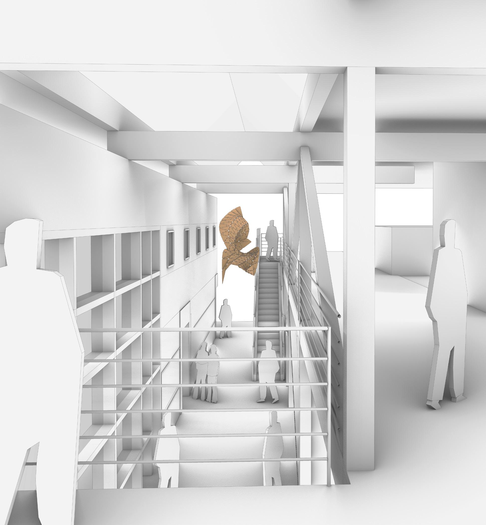
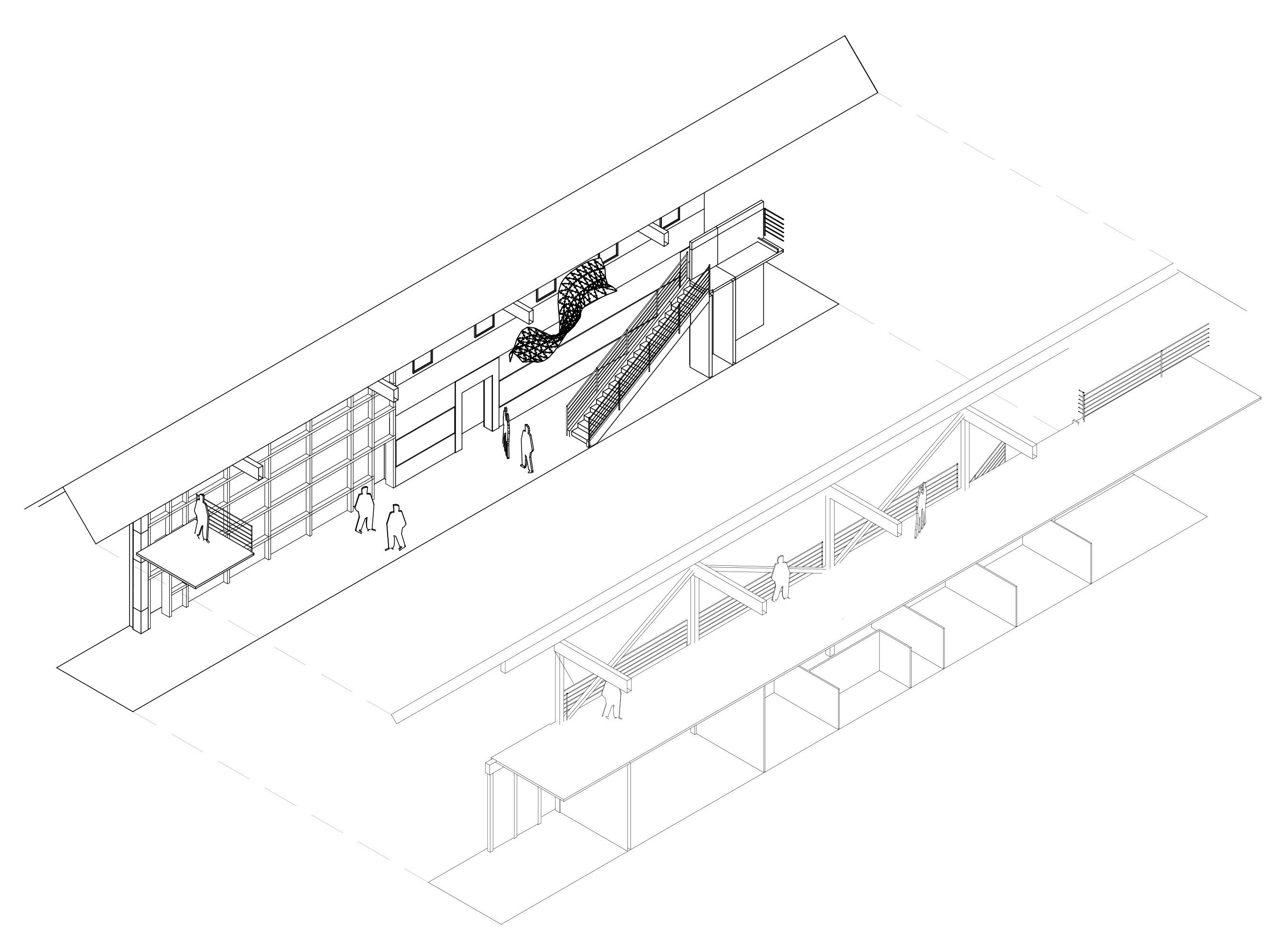
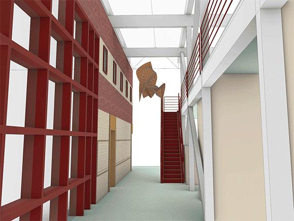
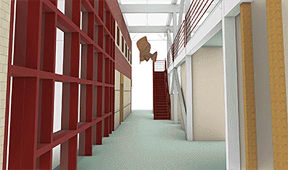
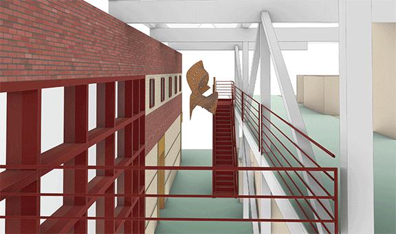
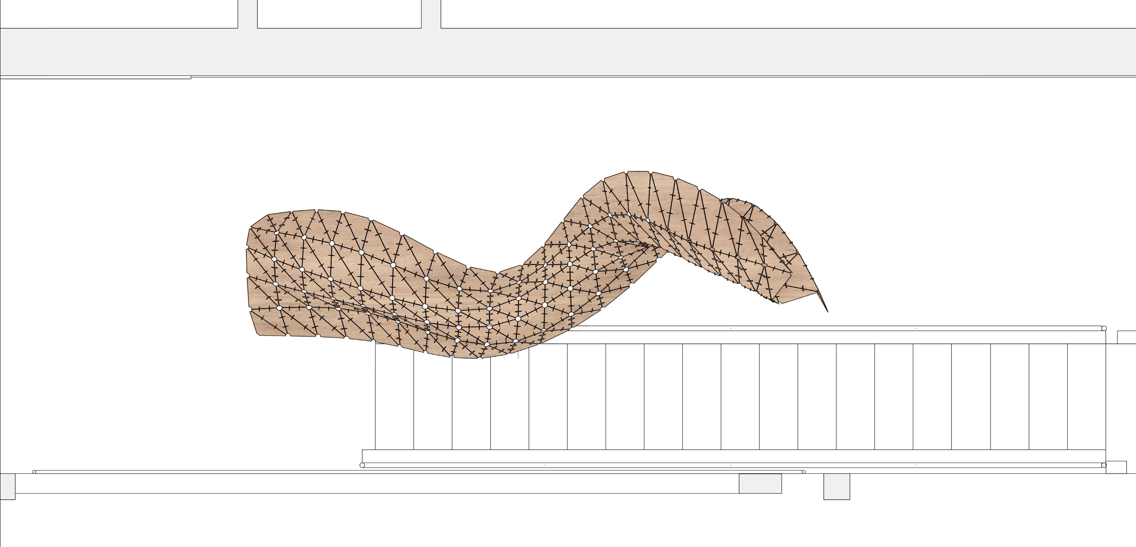
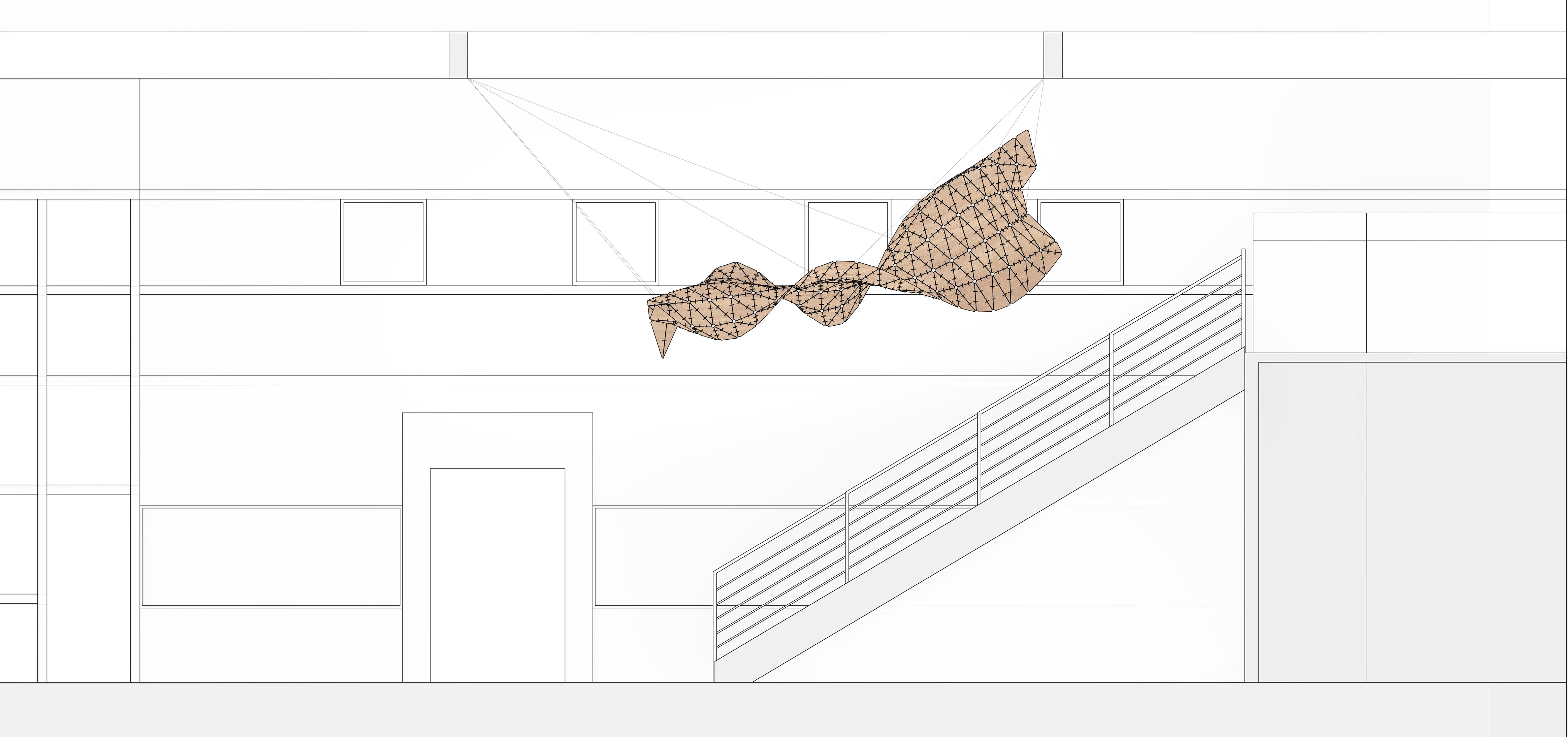
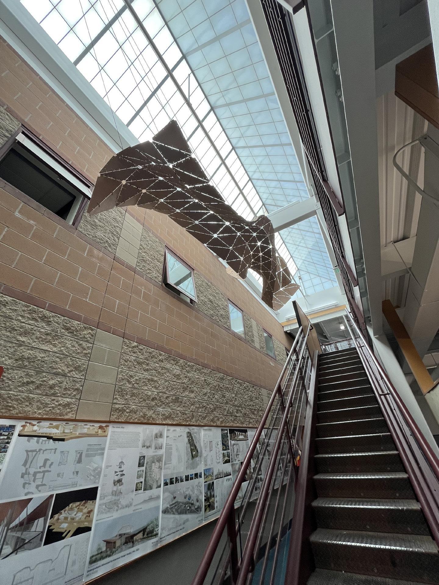
Design Development + Double Curvature
Goals:
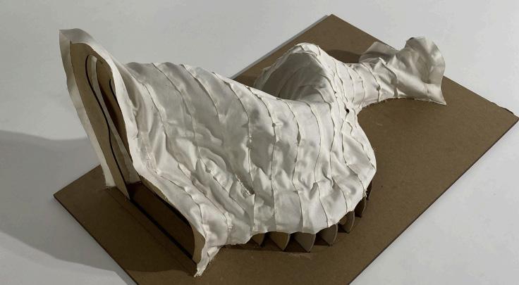
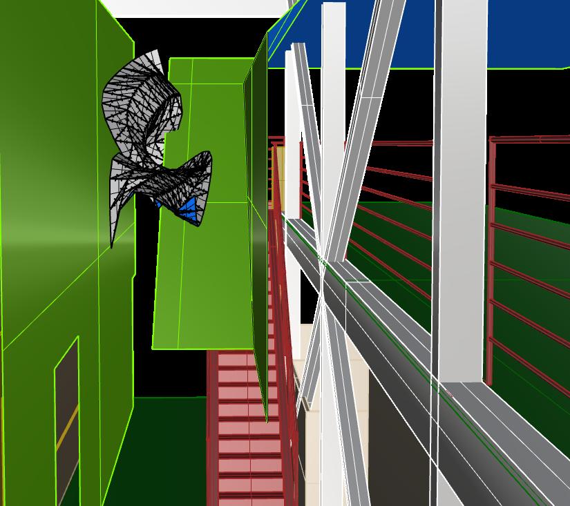
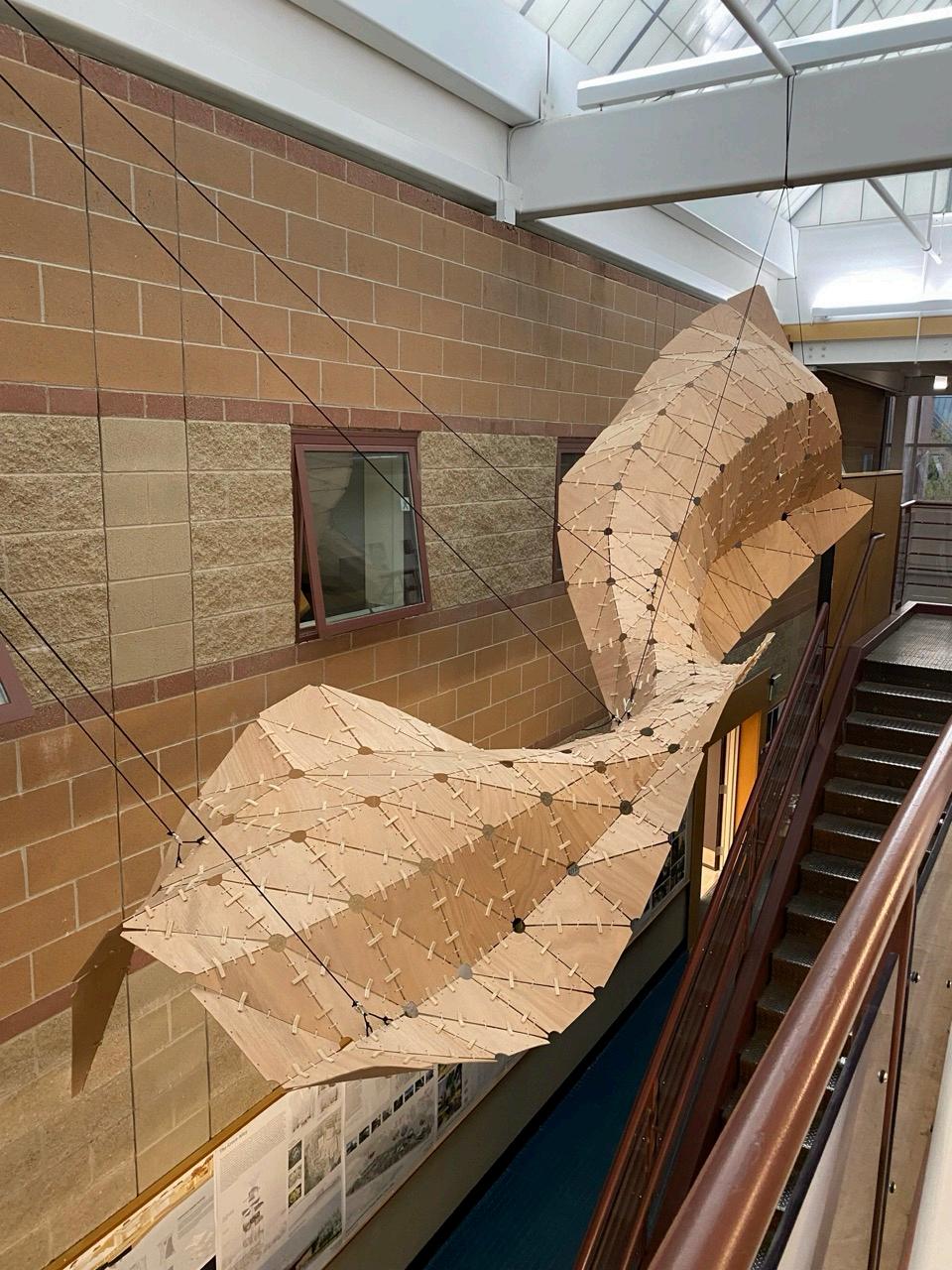
-Develop a form that reacts to the staircase in a way that it morphs around the slope of the stair.
-The form must have enough double curvature so that it mostly supports itself.
-Create a method of discretizing the surface into triangulated pieces.
-Create a surface that can easily be unrolled and nested.
Obstacles:
-Okoume plywood doesn’t flex the same way as Bristol Paper.
-Boundaries of the staircase and windows limited the habitable zone.
-After visiting RIC + The PVD Pedestrian Bridge it was clear that we needed a labeling system for a successful assembly process.
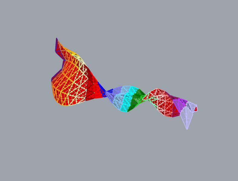
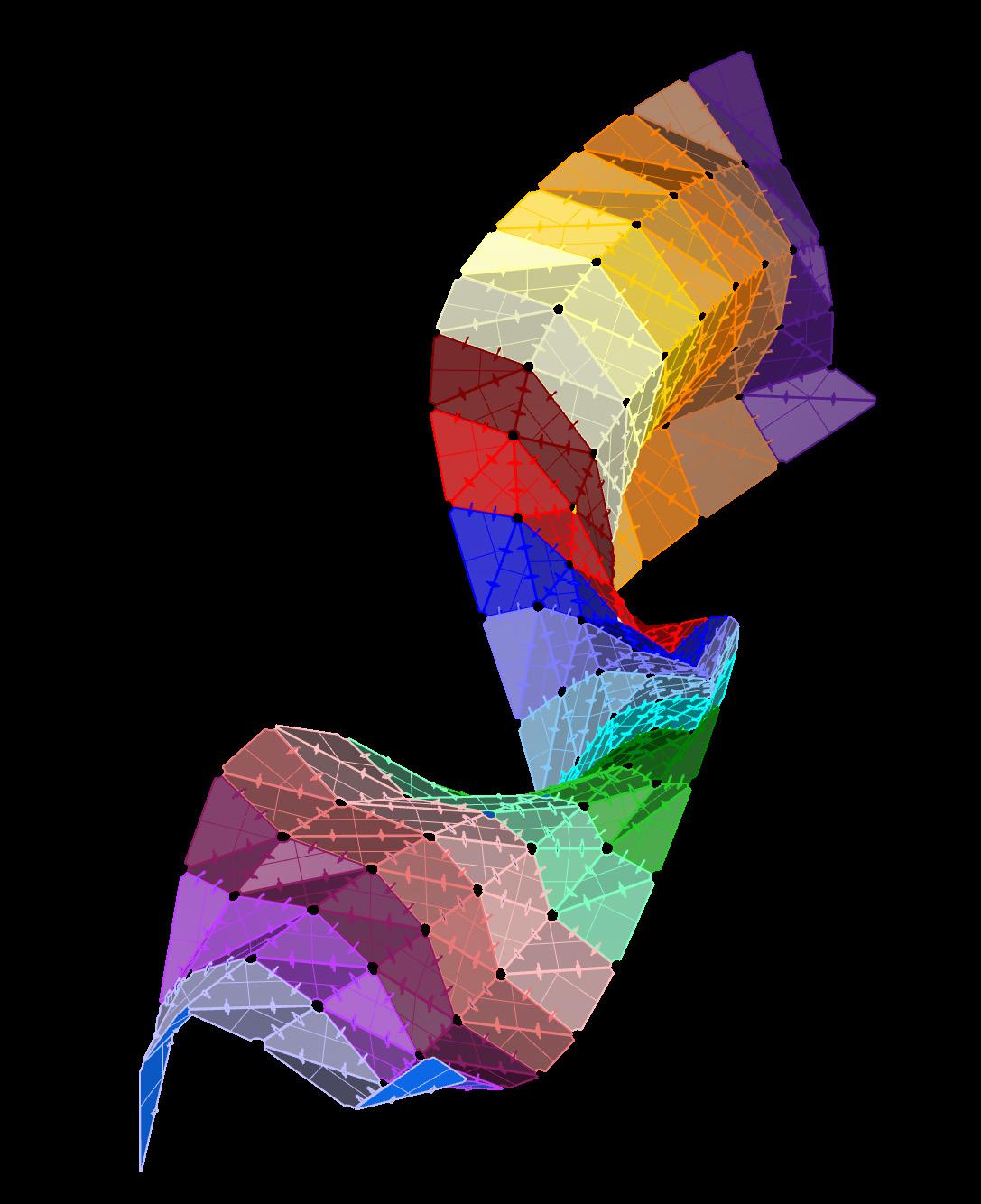
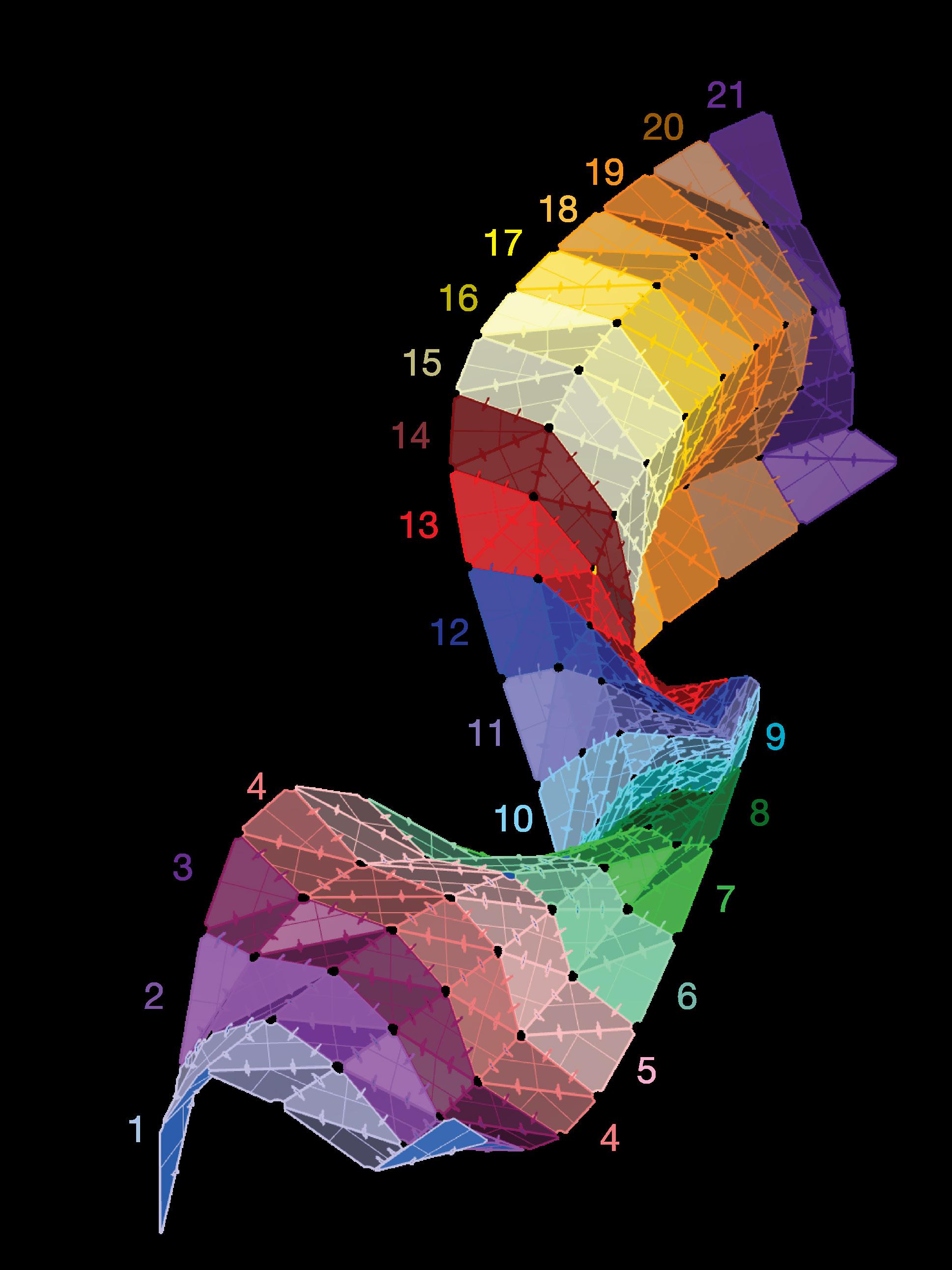
Color Coordinated 3D Model
The Design Team:
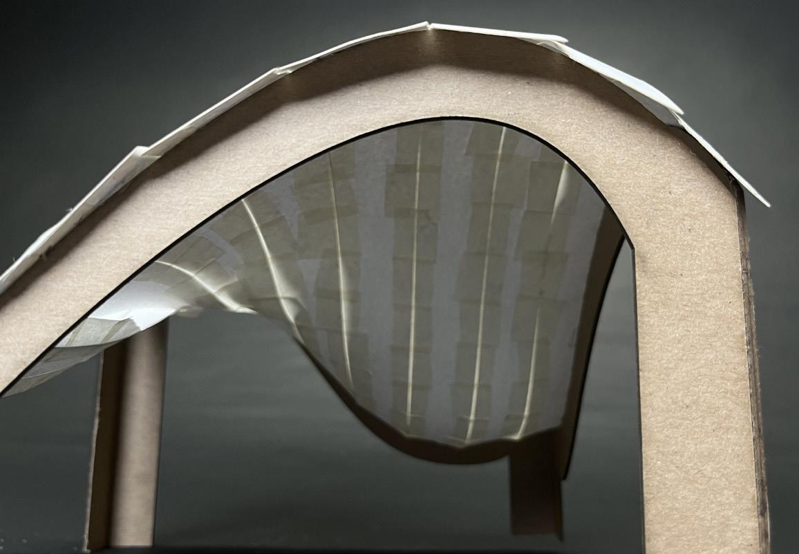
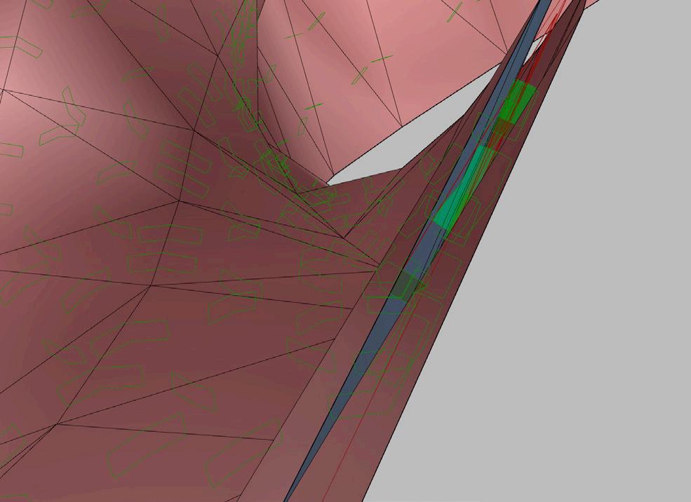
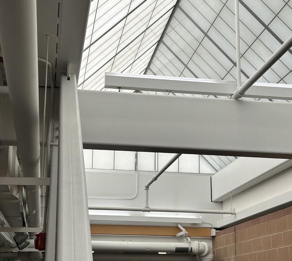
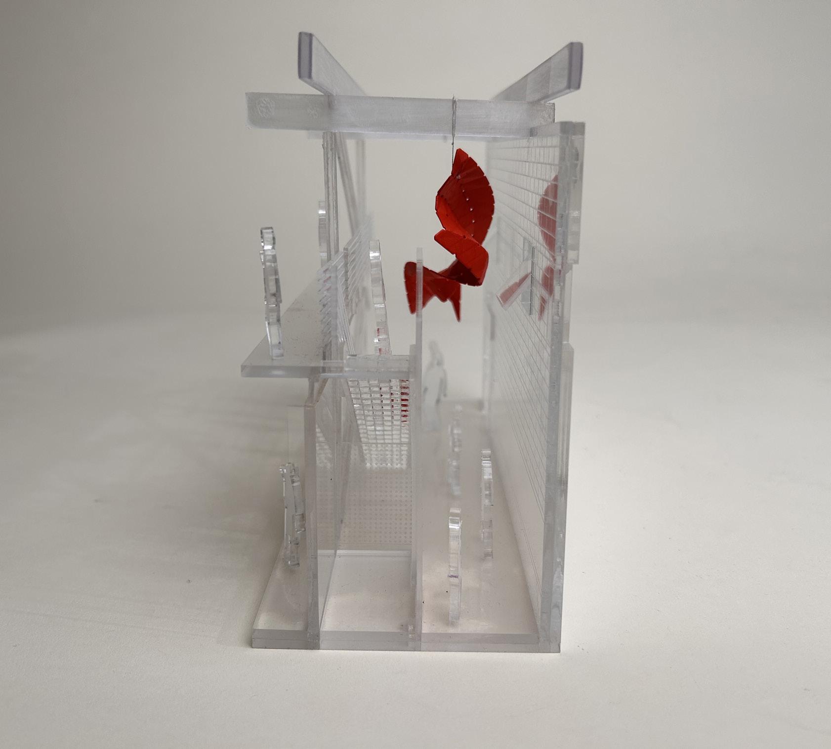
Boundaries + Limitations
Both the staircase and the windows have a clearance allowance of 3’. The surface had to stay out of these boundaries while maintaining the “swoop affect.”
As a team, we agreed that this shouldn’t be something that a passerby would able to reach out and touch.
So working the surface around these boundary “planes,”became necessary.
The beams have lights attached very closely on the topside.
The amount of discretization limited our design shape.
The Design Team:
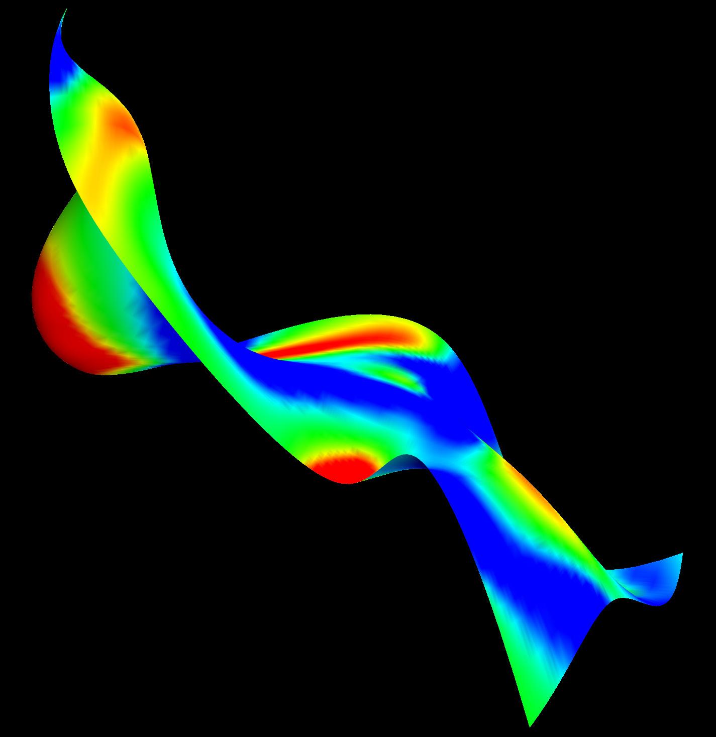
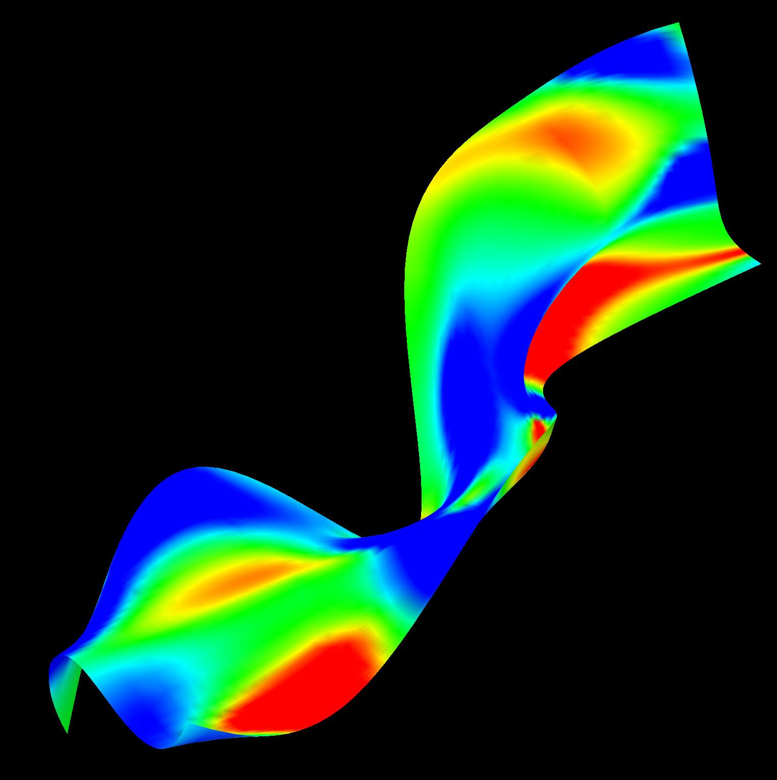
Curvature Analysis
Curvature Analysis Model
Curvature Analysis Model
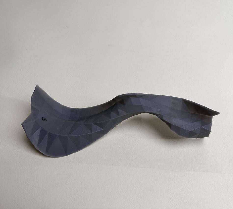
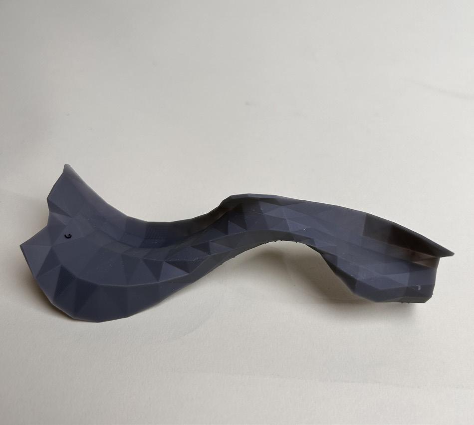
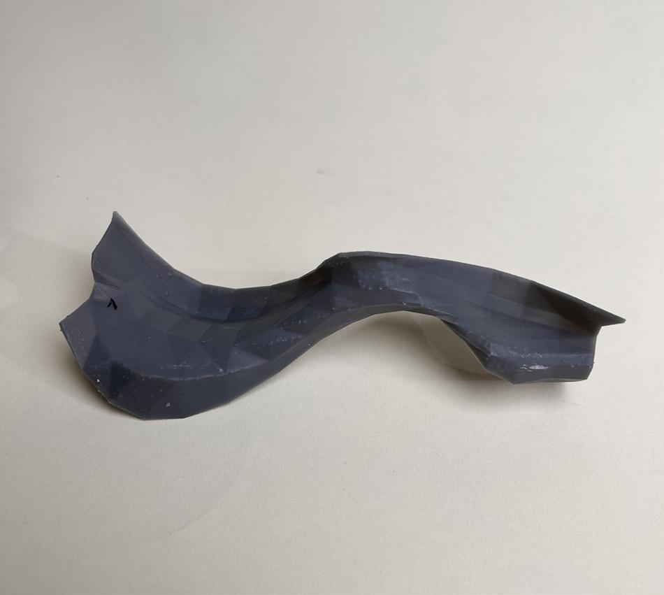
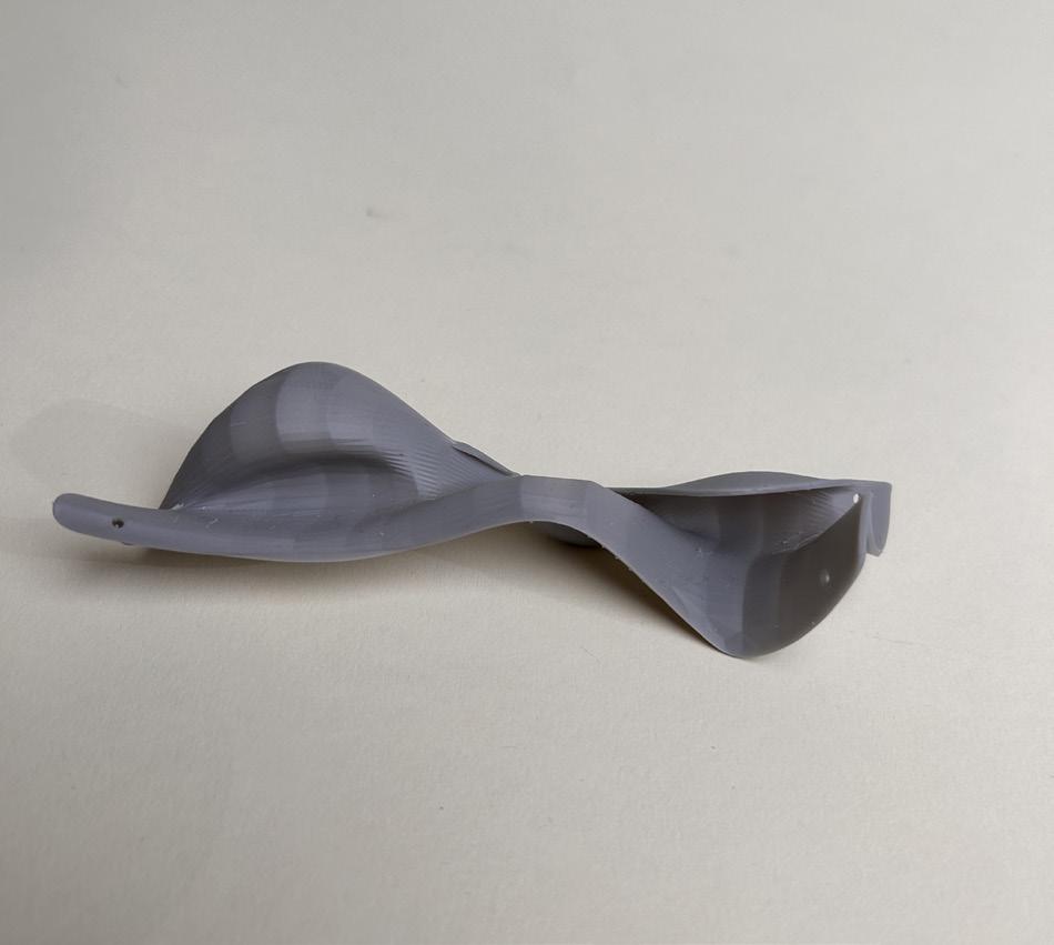
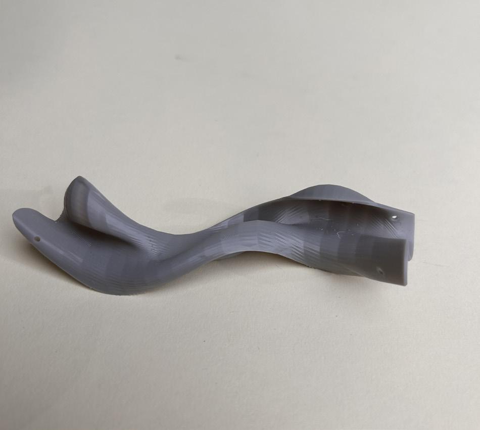
The Design Team: Resin
Printed Iterations
The Design Team:
Resin Printed Iterations
Final Resin Model
Final Resin Model
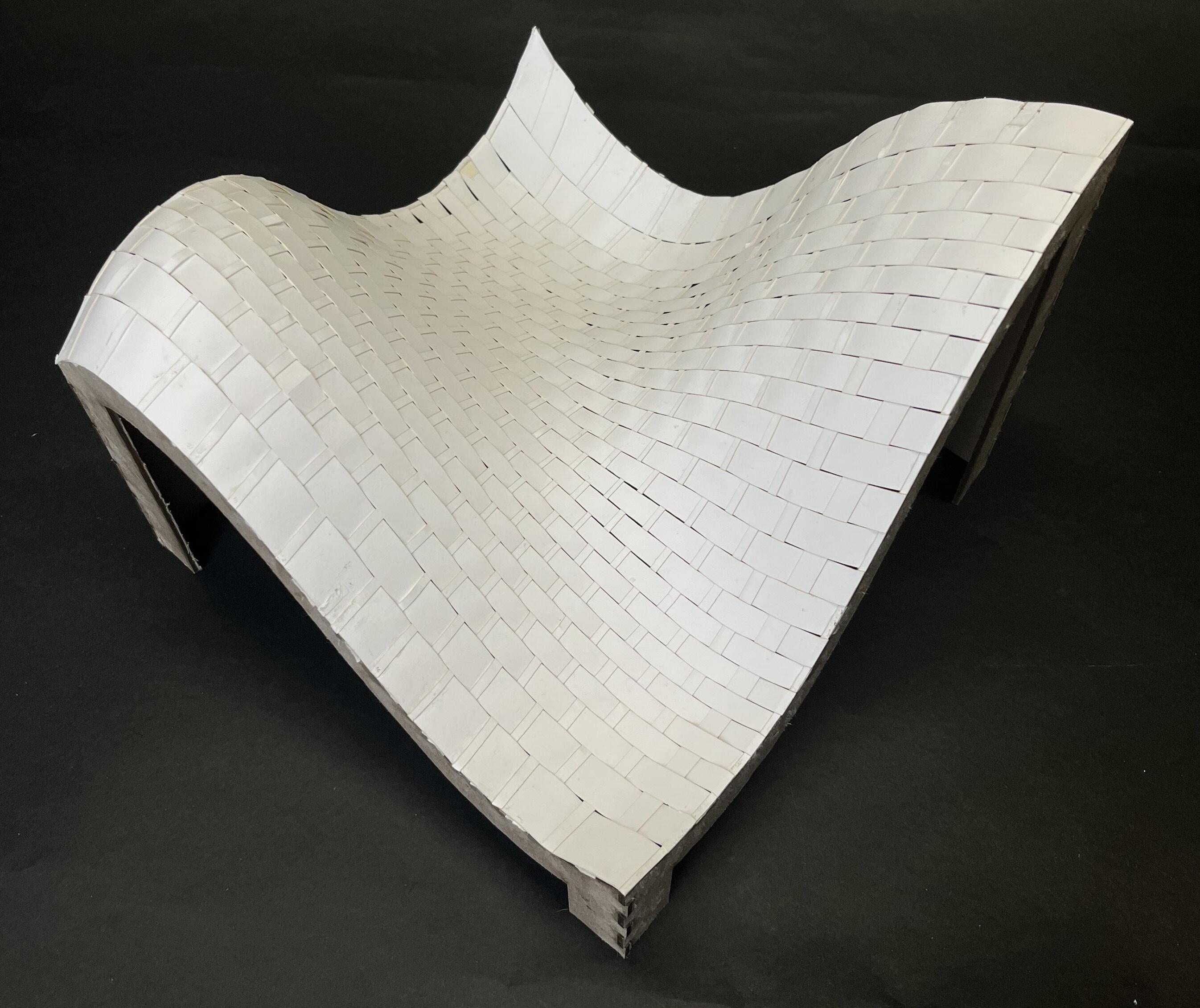
The Production Team:
Focused on developing joinery methods, performing material tests, and building physical models
Zip tie edge connection
Slot edge connection
Unreinforced zipper edge connection
Fishing line zipper edge connection
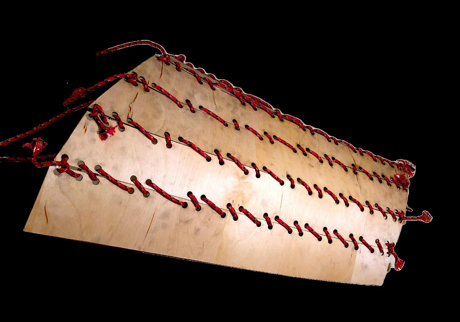
Paracord weaving edge connection
Twine weaving edge connection
The Production Team:
Materiality & Final Joinery Method
-More rigid, keeps its flat shape
-Small issues with warping
-Flexible, strong memory, wants to lay flat
-Snaps easily, weak
-Easily bent, memory of bent shape
-Brittle core, “bending” is breaking
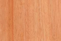
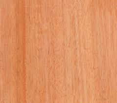
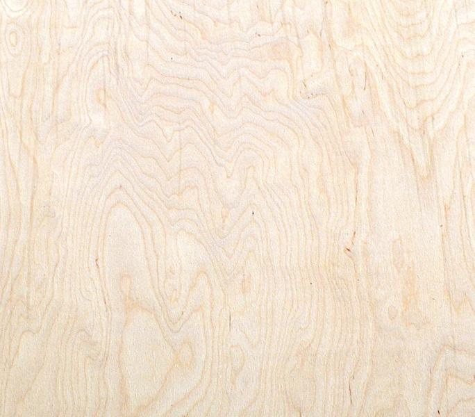
Okoume
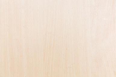
Birch
Poplar
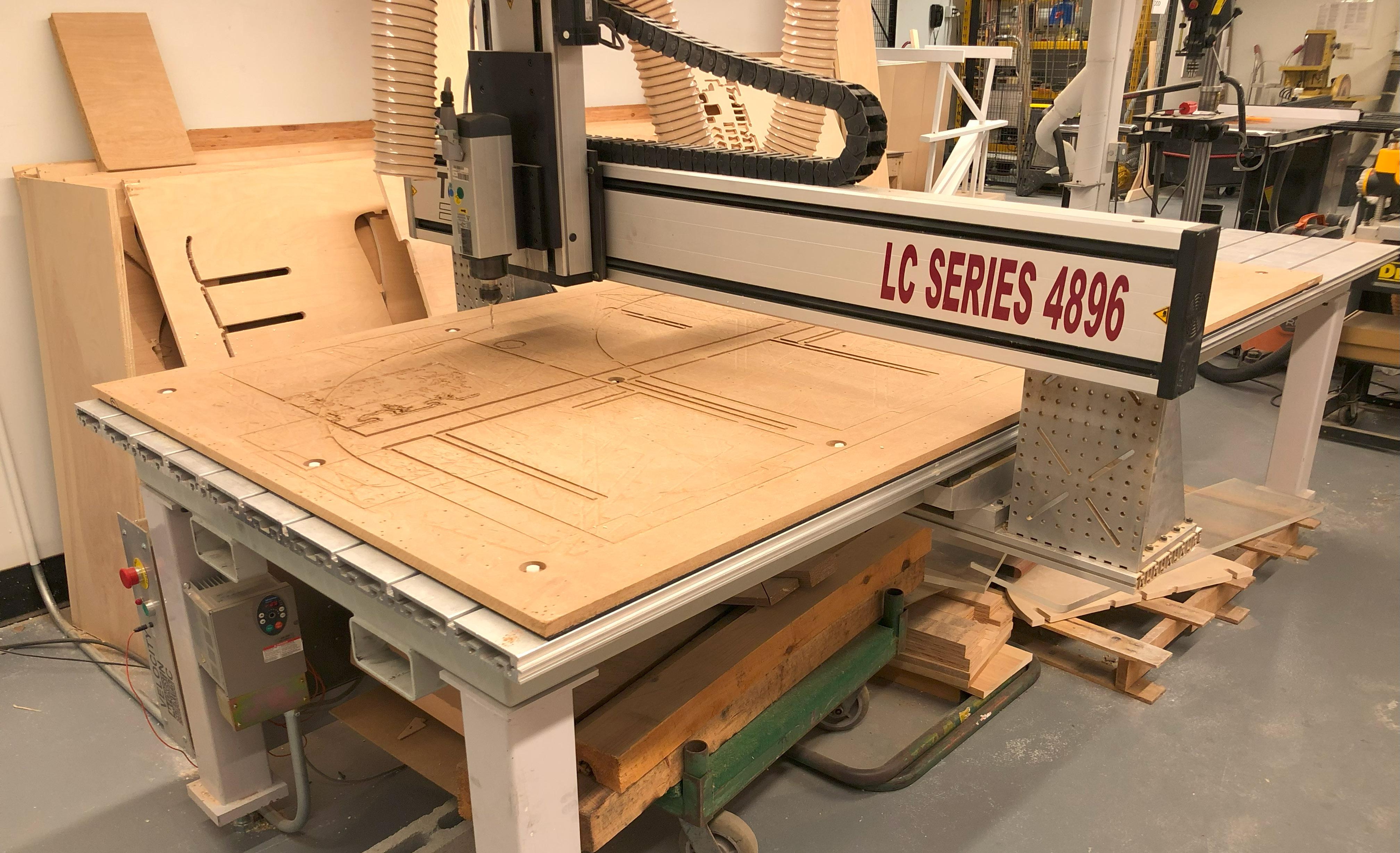
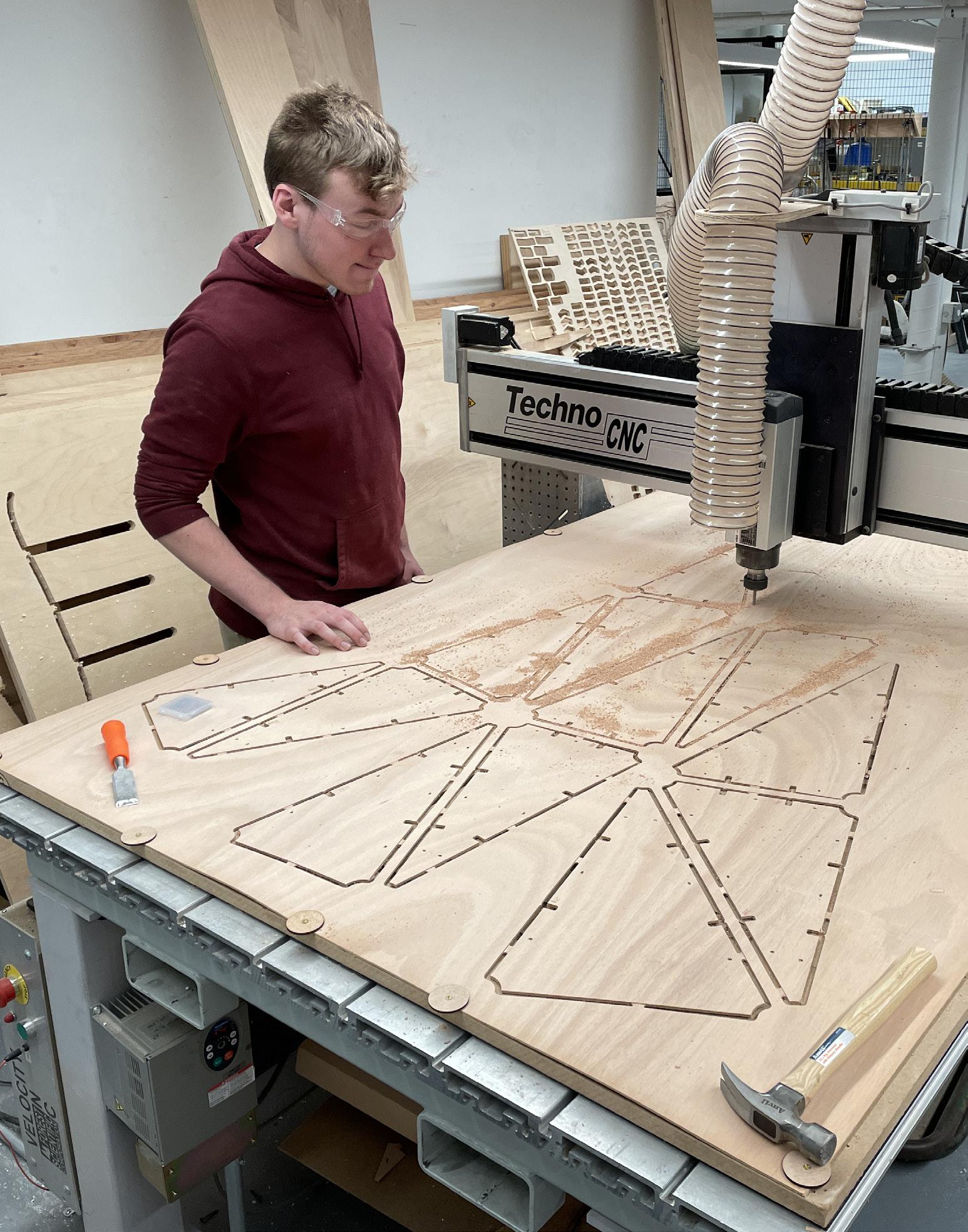
The CNC Router:
Every piece of the final model was cut on our own LC Series 4896 CNC Router. Cutting took just over one week.
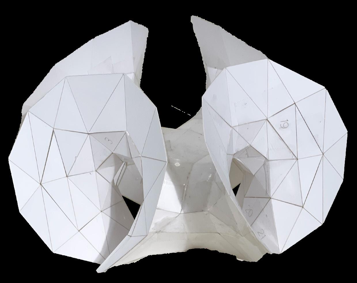
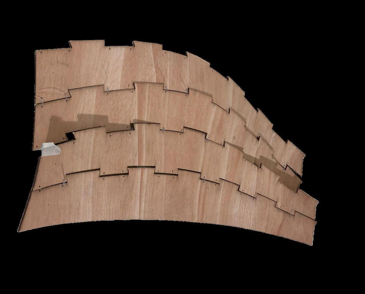
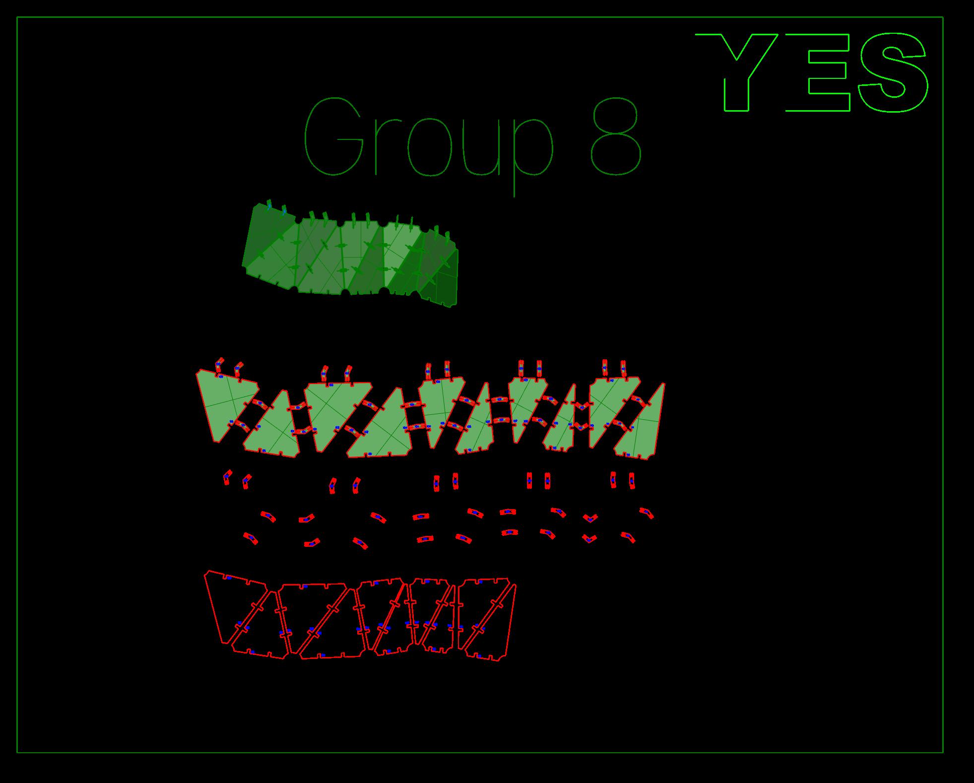
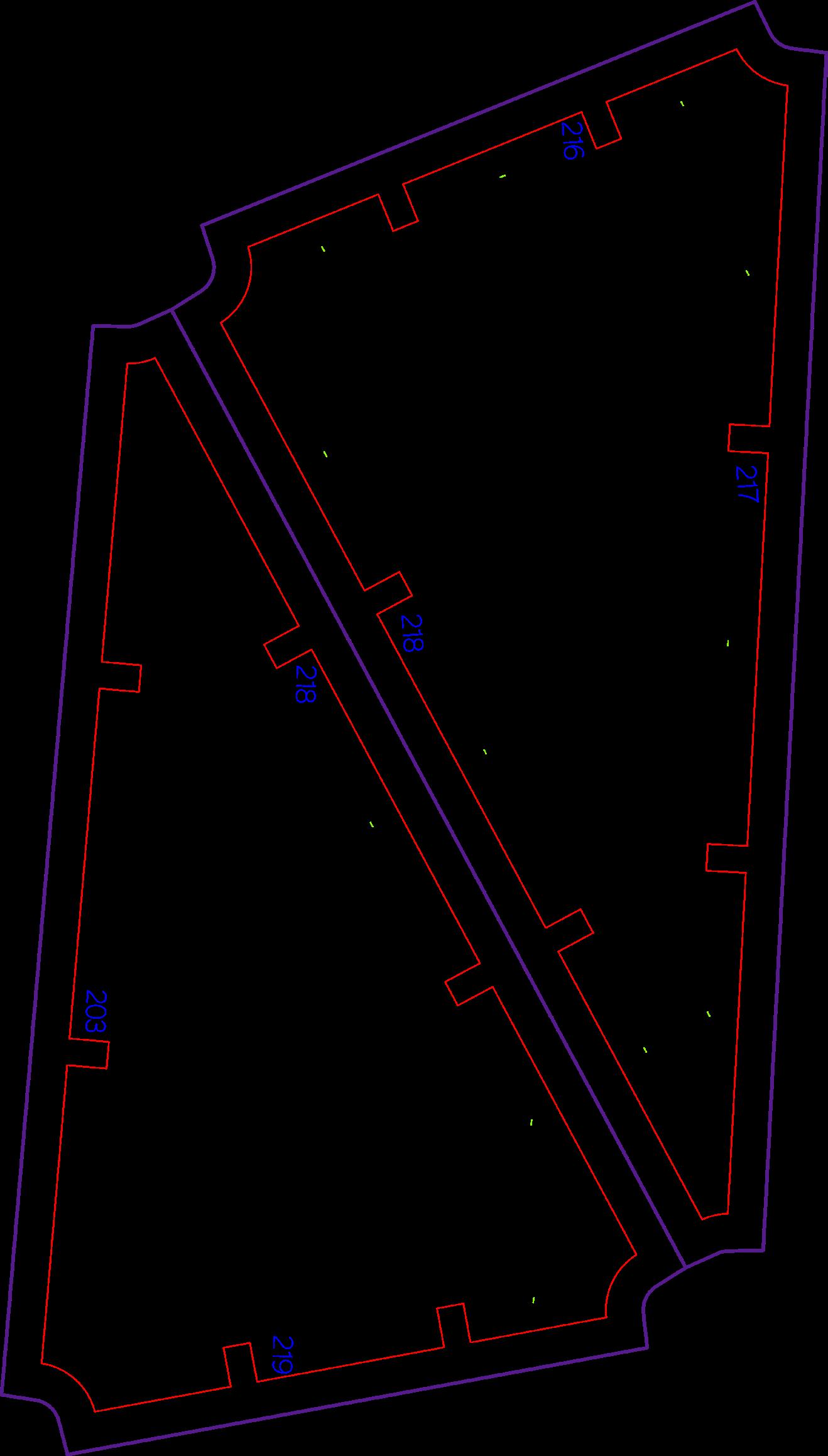
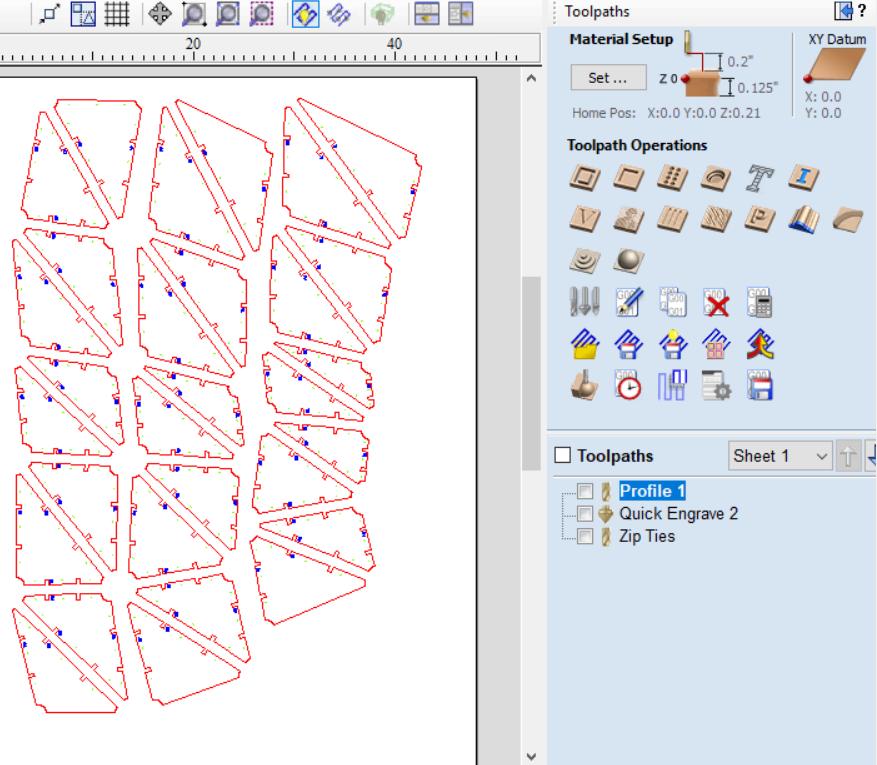
Labeling + Organization:
The surface was split into 21 different groups that were clearly labeled in Rhino.
This made it easier to unroll and label all of the biscuits and panels. This file was passed around a lot so having it clear and conscise helped alot. The strips were individually seperated and unrolled along with being labeled accordingly.
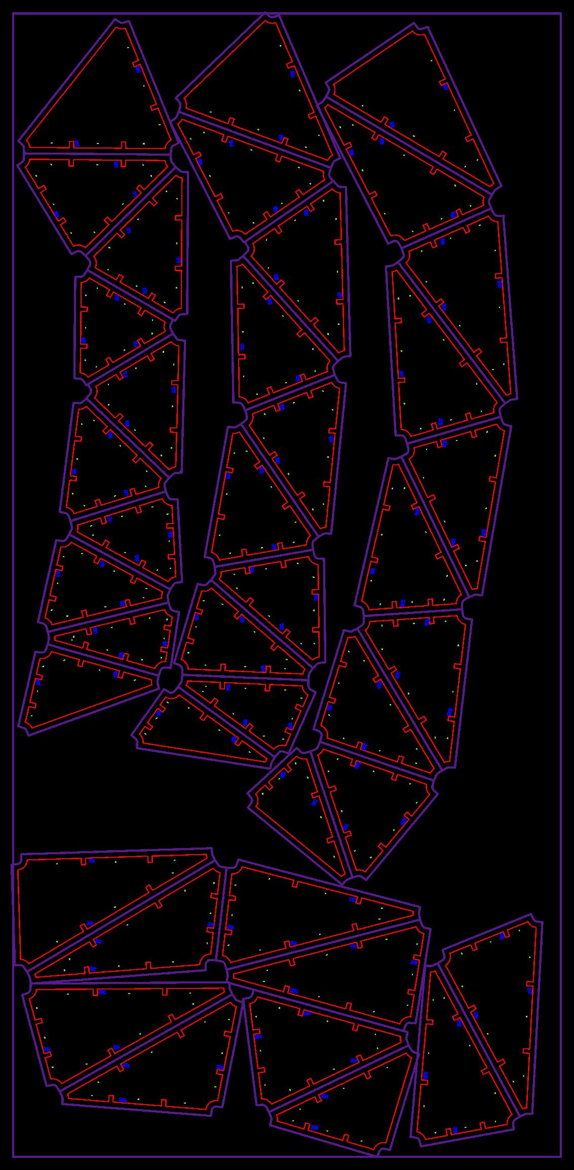
All of the groups were then set into a matrix.
Grouping Diagram
Group Matrix
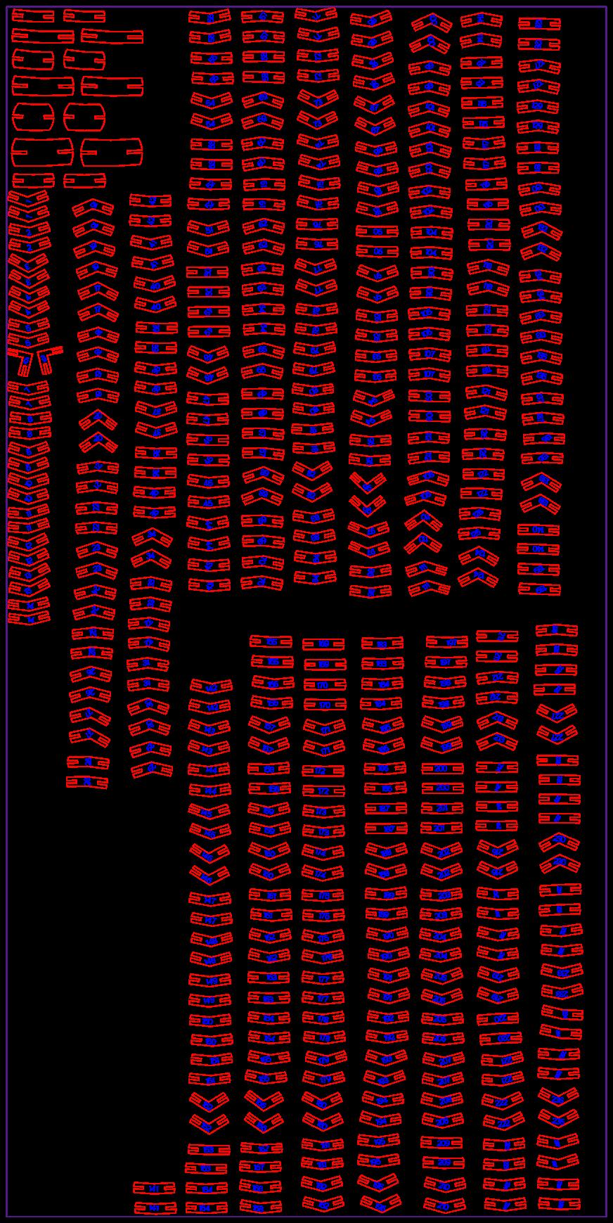
The biscuit nesting strategy was to have 1/4” gap between the biscuits at their closest point
The panel nesting strategy was to have at leat 1/2” between the panels at their closest point.
These strategies would ensure that we waste the least amount of material possible.
Biscuit Nesting Strategy
Panel Nesting Strategy
4’ x 8’ Okume sheets
Approx. 3 groups per sheet
’x 5’ (2: 2.5’ x 5’) Baltic Birch
Approx. 18 groups per sheet
Biscuit Nesting
Panel Nesting
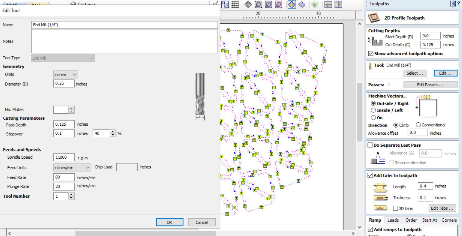
Programming Toolpaths on V-Carve:
Nested Rhino drawings were programmed to be cut by V-carve. Different bits require different toolpaths.
HERO AT WORK
Programming Toolpaths on V-Carve:
Careful consideration of material thickness, feed rate, spindle speed, number of passes, pass depth and more.
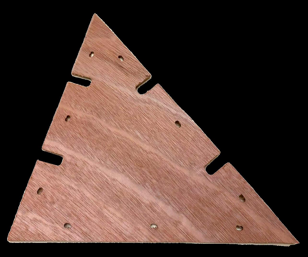
Panel Cut Process:
210 Panels were cut from six 4’x8’ sheets of 1/8” thick Okoume plywood. Each edge has two slots with a number matching a biscuit.
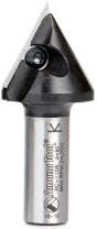
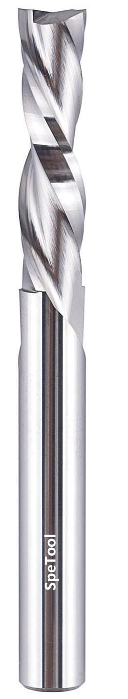
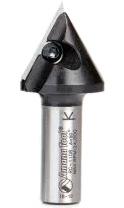
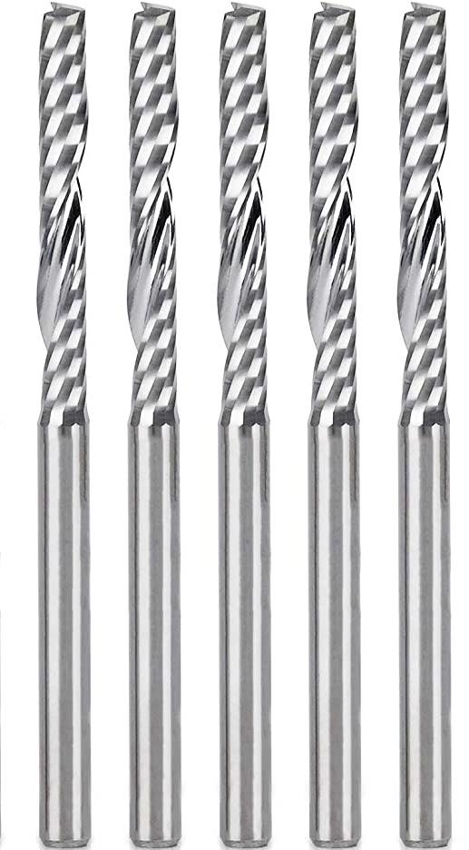
(1)90° V-Carve engraving bit
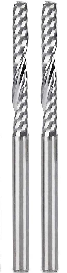
(2)1/8” Flat nose spiral bits
(1)1/4” Flat nose down-cutting bit
(8)4’x8’ sheet
Okoume
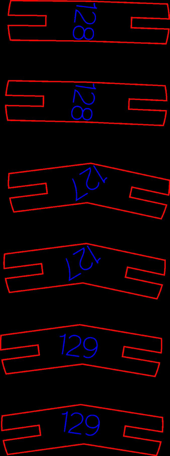
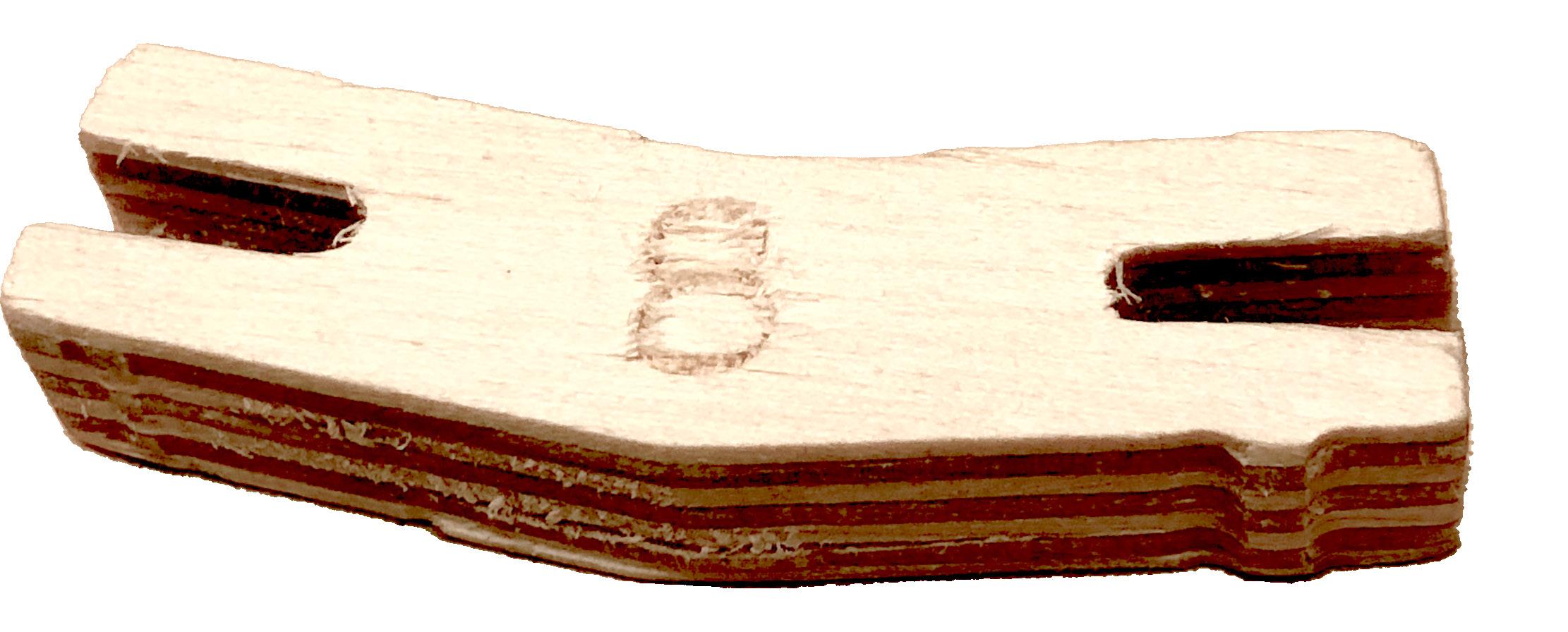
Biscuit Cutting Process:
578 Biscuits were cut out of one 5’x5’ sheet of Baltic Birch plywood. There are two of each biscuit with a respective angle and number.