Jefferson University - College of Architecture & The Built Environment
Bachelor of Architecture & Custom Minor in Architectural Pedagogy
grace garlin
CONTACT
(814)-330-4182
gracegarlin10@gmail.com
HARD SKILLS
Knowledge in Autodesk’s AutoCAD and Revit, Adobe designs Illustrator, Photoshop, and InDesign, and Rhino.
SOFT SKILLS
Strong desire to learn and improve on new and existing skill sets. Effective communication and time management skills, and a good team player.
PROFILE
I am a fifth-year architecture student with a strong aptitude for conceptualizing and designing innovative architectural solutions. Profucent in a range of industry standard software, I am actively seeking opportunities to gain hands-on experience and contribute to projects through work in the architectural field.
EXPERIENCE
Phillips & Associates Architects, LLC, June 2024 - Present Working in AutoCAD within all phases of the deisgn process, as well as experiecning surveying construction sites.
Architectural Teacher’s Assistant, Fall 2024
Assisted first year architecture students with conceptual and graphic skills
Architectural Education & Photography, Fall 2025 - Spring 2026
An independent study connecting the process of architectural education and photography.
Architectural Tutor, Thomas Jefferson University, January 2025 - Present
Tutor architecture students in an assortment of architectural courses
Worked on concerting sketches into AutoCAD drawings
INVOLVEMENT
Phi Alpha Chapter of Tau Sigma Delta Honor society in Architecture and Allies Arts, only natonal honor society for architecture and design majors that is accredited by the Association of College Honor Societies.
Teachers Assistant Position, 2020-2021
Assisted high school students in introduction courses in Architectural Drafting & Design.
EDUCATION
State College Area High School, State College, PA
High School Diploma
May 2021
Thomas Jefferson University, Philadelphia, PA
CPS: 3.91 | Deans List Fall 2021 - Present
Bachelor of Architecture (B.Arch)
Expected May 2026
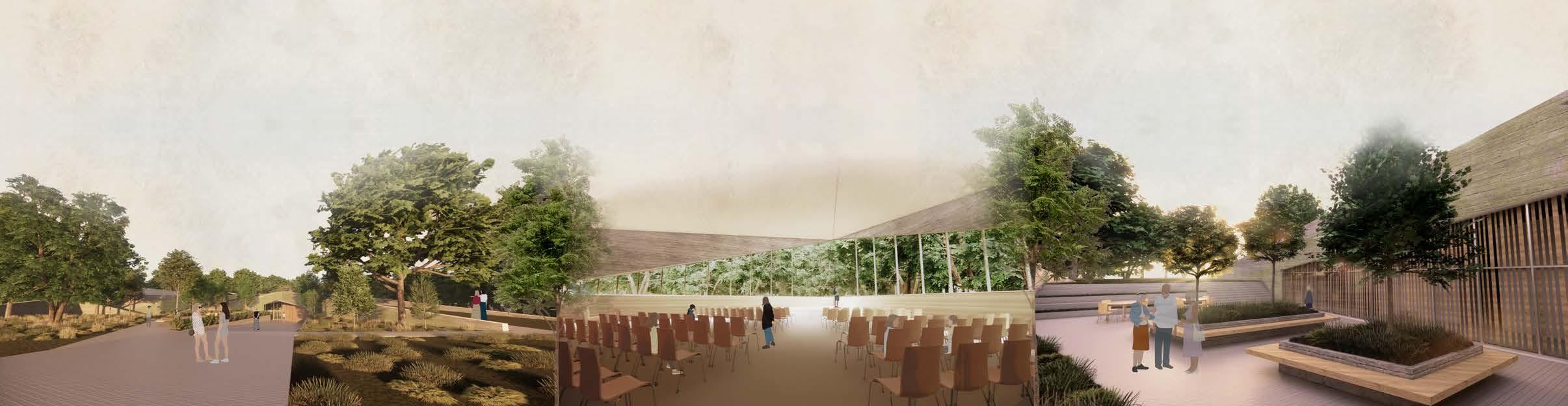
In collaboration with two of my peers, this semester long project incorporates all of our previous classes into one comprehensive studio. By using what we learned in out structures and technology classes we were able to complete the design and documentation for a non-denominational sanctuary located in Blue Bell Park, Philadelphia PA
Non- Denominational Sanctuary
Fall 2024
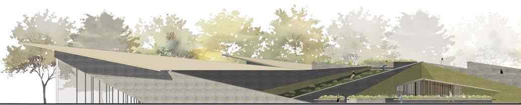
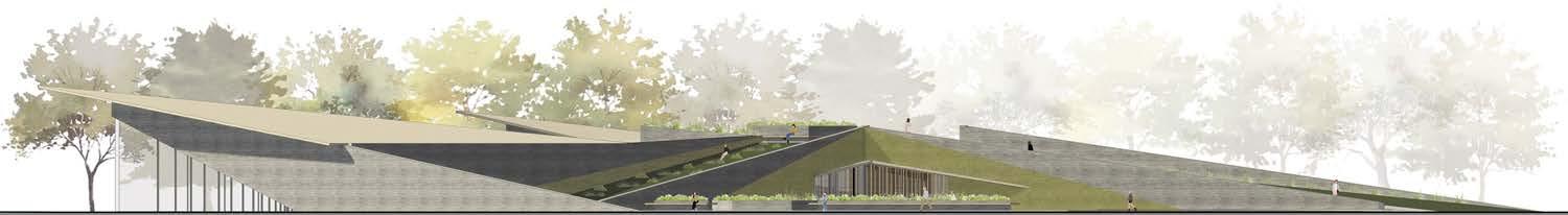
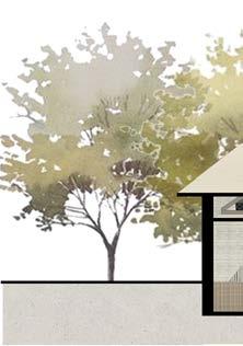
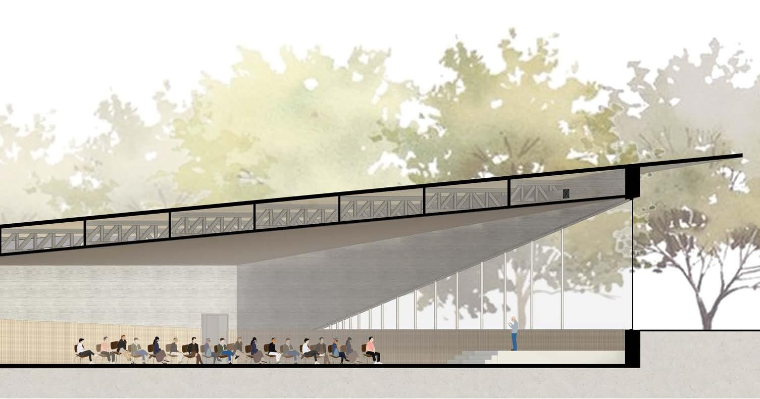
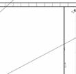
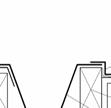
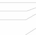
East Elevation
Through the sculpting of the Wissahickon’s landscape with out architecture, a deeper sense of place and thought for all spiritualities is created to foster a sense of community in a setting with a strong connection between the built environment and nature
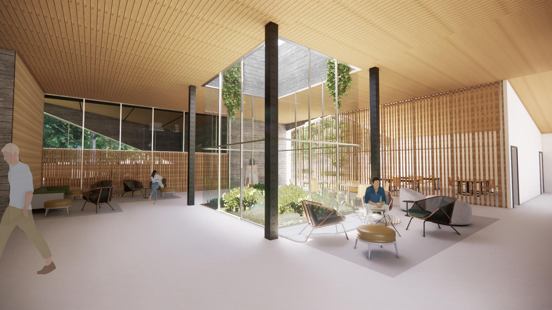
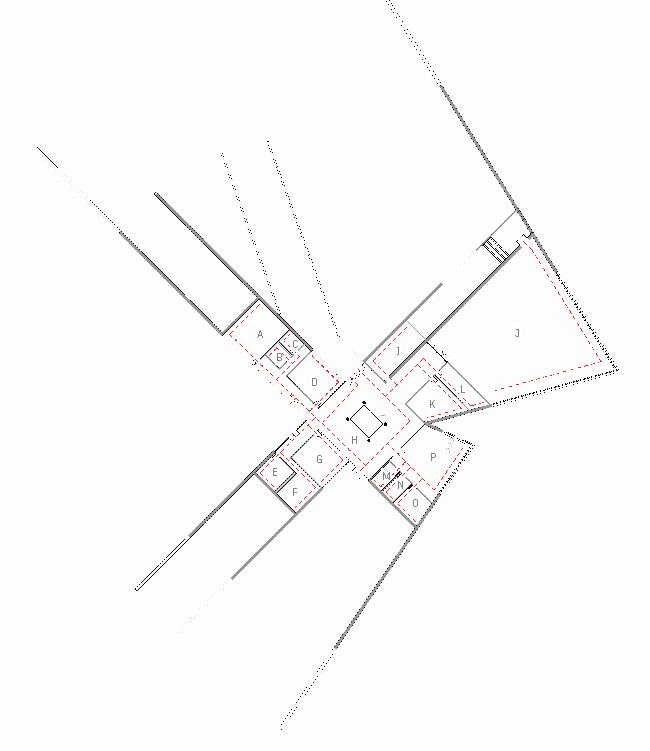
Common Room View
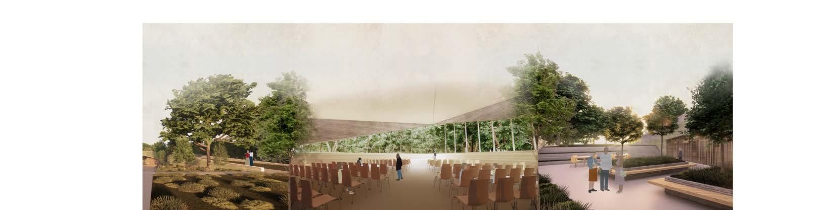
We chose to angle the views within the sanctuary and chaped into the trees to create a sense of tranquility on the site. Seen in the site plan, we extended the existing path to connect to out building. As you approach the building, the landscape slopes down to bring you from an elevation of +0’-0” to -5’-0” where the floor level sits. One enters into the main common space where four wings branch off from the center. Using the geometry we created exterior courtyards that connect back up to the site.
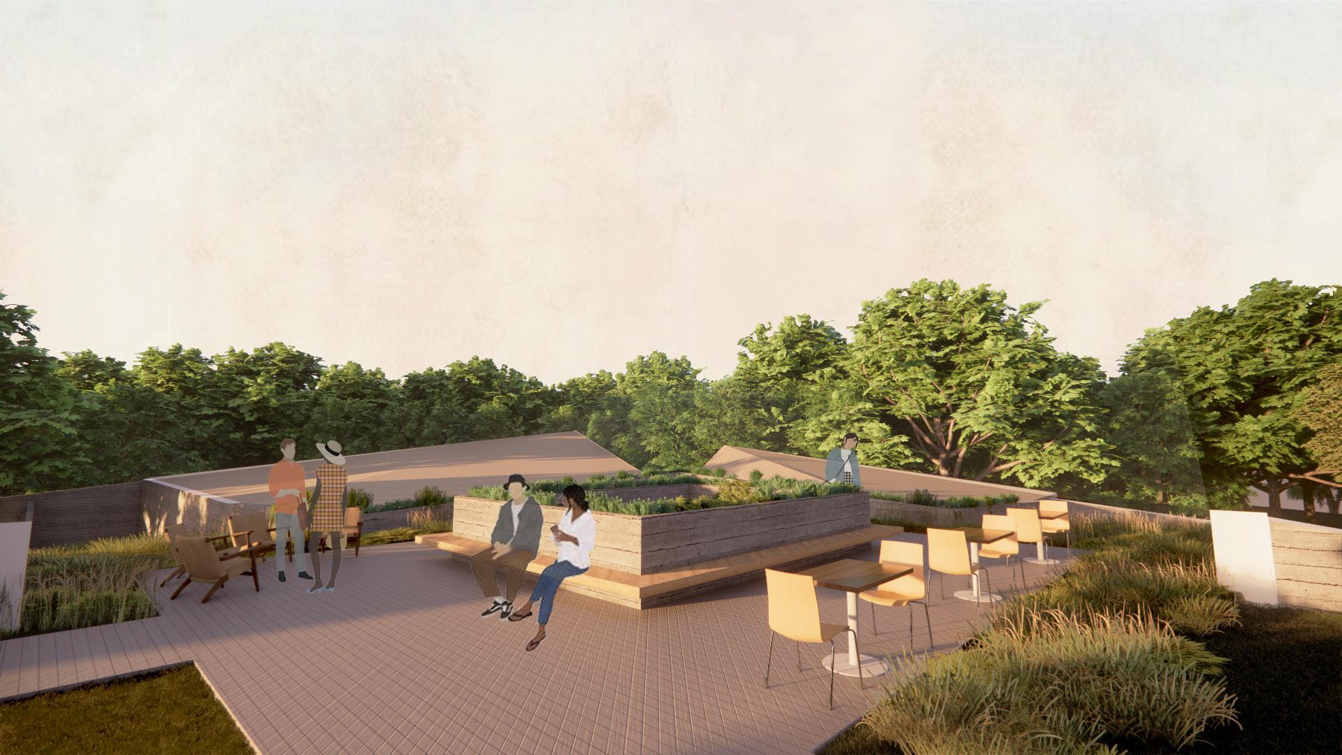
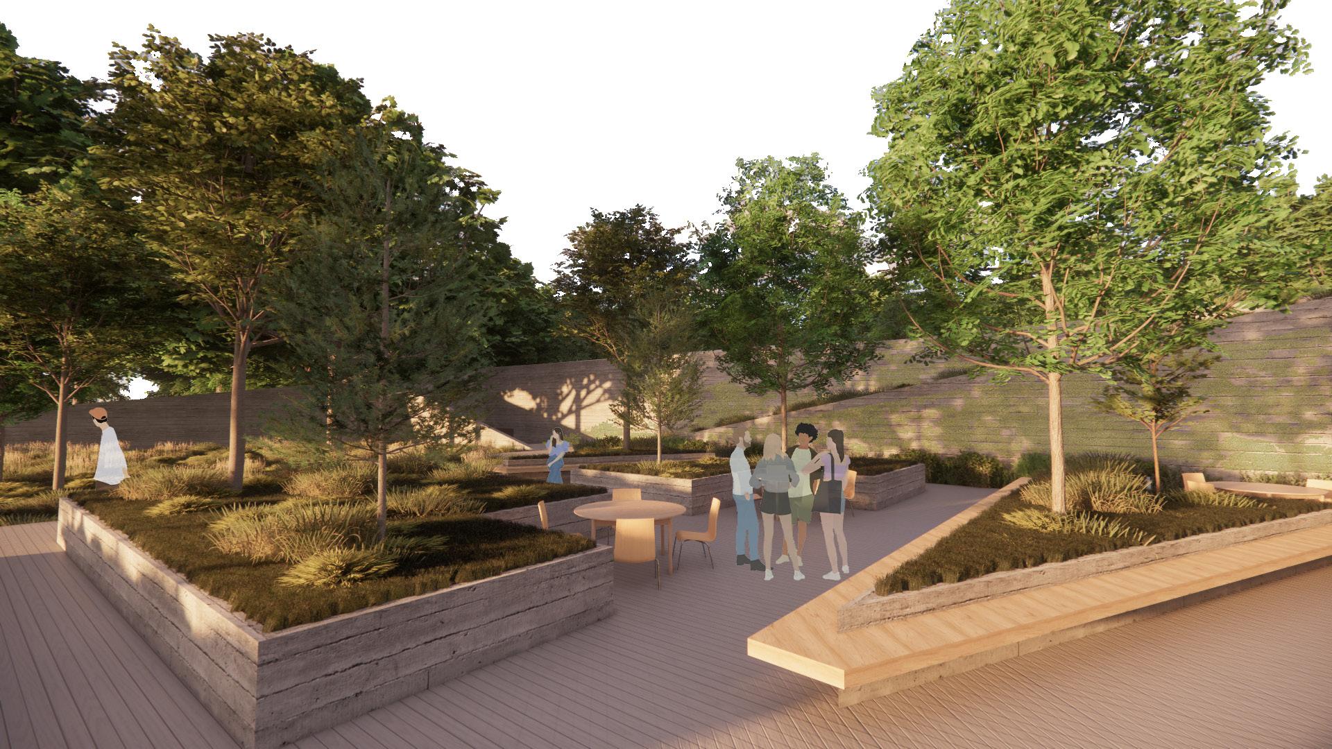
Sanctuary View
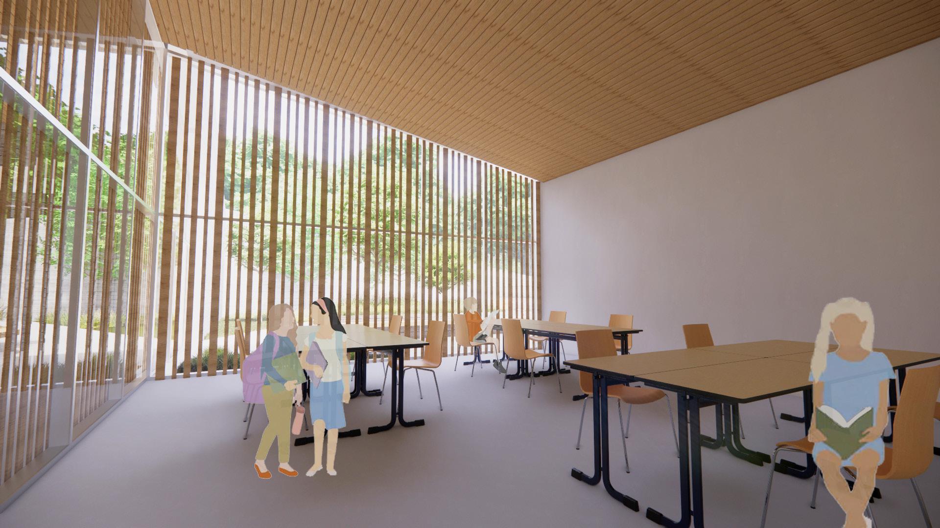
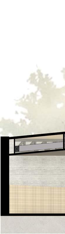
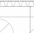
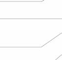
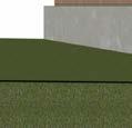
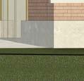
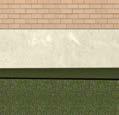
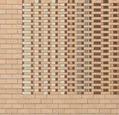
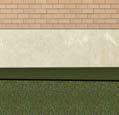
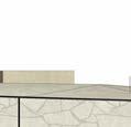
Sanctuary and chapel roofs angle upwards to open up the view into the trees, immersing the users into the natural beauty of the Wissahickon. The roofs of the support wings angle down and hit into the landscape, creating green roofs that can be accesses from the exterior. We used board formed concrete as a strong material that can successfully anchor the building into the ground and look monolithic. We also used wooden screening as a natural material that adds warmth to contrast against the concrete and as a shading device in highly glazed areas.
North Elevation
South Elevation
West Elevation
Classroom View
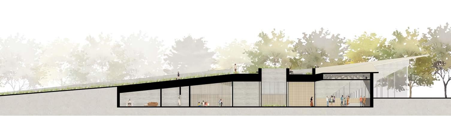
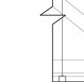
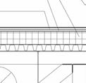
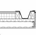
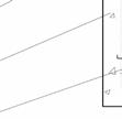
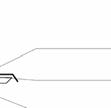
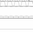
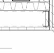
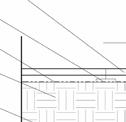
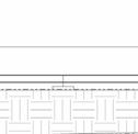
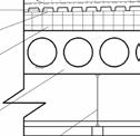
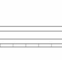
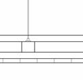
Atrium Section
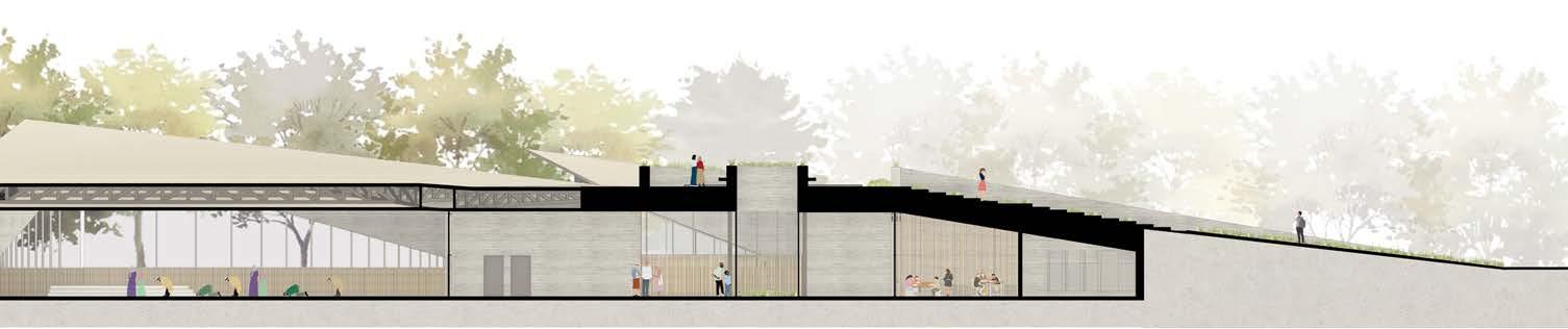
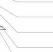
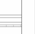
Chapel Section
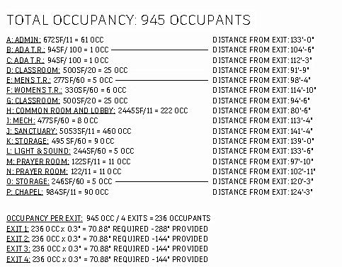
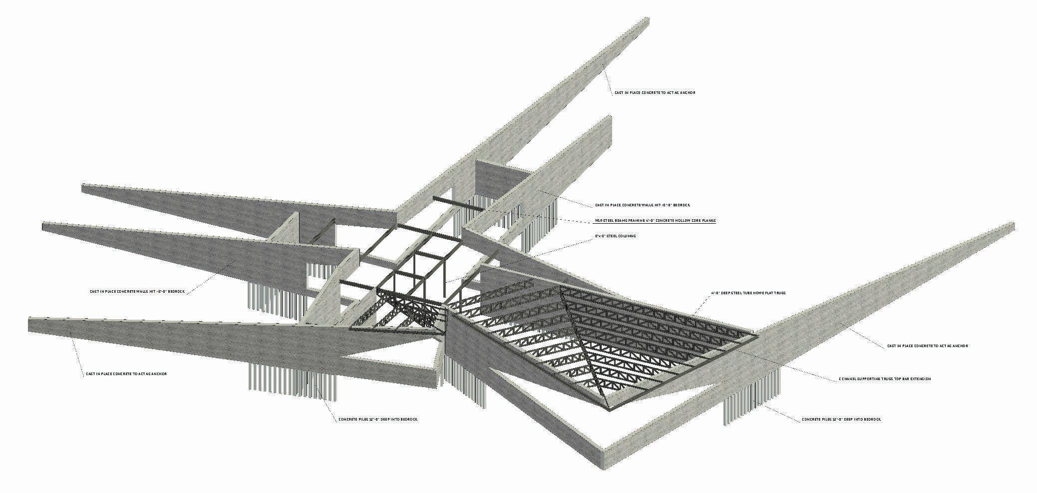
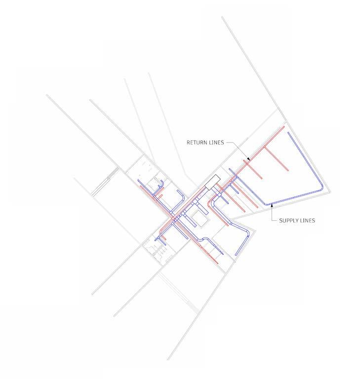
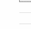
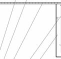
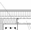
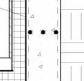
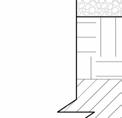
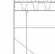
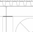
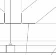
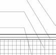
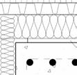
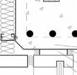
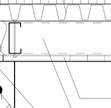
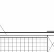
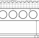
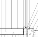
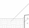
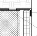
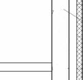
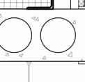
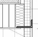
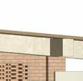
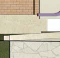
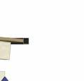
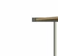
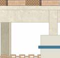
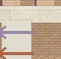
The exterior walls of our building are made of load bearing cast in place concrete which anchor into the ground to help physically and visually tie the building into the landscape. These walls reach 8 feet deep to hit the bedrock, from there, concrete piles are drilled 12 feet down to allow certain spaces to remain uninterrupted by excess columns. With the concrete, W16 steel beams are used to frame 4 feet concrete hollow core planks that act as a secondary structure, through the support wrings. 4 doot deep steel tube howe flat trusses are used in the sanctuary and chapel as a way to keep those spaces uninterrupted. The top bar of these trusses extent over the structural concrete wall to support the roof overhang of the sanctuary and chapel. We decided to use a VAV system for our HVAC to provide precise climate control by varying the airflow to different zones winthin the building.
3" METAL DECKING
6" RIGID INSULATION
3/4" PLYWOOD
1" METAL ROOFING
HVAC BEHIND
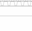
4' DEEP STEEL TUBE
HOWE FLAT TRUSS
WIRE CEILING HANGERS
4" STEEL CEILING GRID
1" WOOD PANEL CEILING
BATT INSULATION
PRECAST CONCRETE
FINISHED WOOD PLATE
WOOD BLOCKING FLASHING
ROOF GUTTER
C 15x50 STEEL CHANEL
1" WOODEN PLANK SOFFIT
TRUSS TOP BAR EXTENSION
EMBEDDED #8 STEEL REBAR
4" RIGID INSULATION
18" CAST IN PLACE CONCRETE
WELDED STEEL TO STEEL CONNECTION
WIRE CEILING HANGERS
4" TWO PART STEEL CEILING GRID
EMBEDED #8 STEEL REBAR
16" CAST IN PLACE CONCRETE
6" RIGID INSULATION
5/8" GYPSUM BOARD
1" WOOD PANELING
1" WOOD PANEL CEILING
4' DEEP STEEL TUBE HOWE FLAT TRUSS
BATT INSULATION
12 MIL PLASTIC VAPOR BARRIER
6" CAST IN PLACE CONCRETE
6" RIGID INSULATION
PRECAST CONCRETE
METAL STUDS WITH SCREWS
COMPACT GRAVEL INFILL
WELDED STEEL TO STEEL CONNECTION
WIRE CEILING HANGERS
4" TWO PART STEEL CEILING GRID
1" WOOD PANEL CEILING
4' DEEP STEEL TUBE HOWE FLAT TRUSS
BATT INSULATION
PRECAST CONCRETE
METAL STUDS WITH SCREWS
1" METAL ROOFING
3/4" PLYWOOD
6" RIGID INSULATION
3" METAL DECKING
METAL FLASHING
1 1/2"x 1 3/4" STEEL ANGLE
WOOD BLOCKING
1" WOODEN PLANK SOFFIT
ROOF GUTTER
C 15x50 STEEL CHANEL
METAL STUDS
TRUSS TOP BAR EXTENSION
BEARING PLATE
EMBEDDED #8 STEEL REBAR
4" RIGID INSULATION
WIRE HANGERS
18" CAST IN PLACE CONCRETE
EXPANSION BOLT
SILICONE SEALANT
STEEL SPACER
8"x 3" MULLIONS
1' GROWTH MEDIUM
FILTER SHEET
2" DRAINAGE SYSTEM
WEATHER BARRIER
4" RIGID INSULATION
1' HOLLOW CORE CONCRETE PLANK
WIRE CEILING HANGERS
4" TWO PART STEEL CEILING GRID
1" WOOD PANEL CEILING METAL TROPH 9" GROWTH MEDIUM
6" GRADE BEAM W/ STEM WALL 12"x12" CONC. POST (BEYOND)
WIRE CEILING HANGERS
4" TWO PART STEEL CEILING SYSTEM
1" WOOD PANEL CEILING
ADJUSTABLE PEDESTAL
2" ROOFTOP PAVERS
ROOF MEMBRANE
GROWTH MEDIUM
GROWTH MEDIUM
ALUMINUM TROPH
GRASS
GROWTH MEDIUM
FILTER SHEET
2" DRAINAGE SYSTEM
WEATHER BARRIER
6" RIDID INSULATION
1' HOLLOW CORE
CONCRETE PLANK
WIRE CEILING HANGERS
4" TWO PART STEEL CEILING SYSTEM
1" WOOD PANEL CEILING
METAL ANGLES, BOLTED TO CONC.
STEEL PLATE
12" CMU, GROUTED SOLID
4" PRECAST BOARD-FORMED CONCRETE PANELS
WEATHER BARRIER
3" RIGID INSULATION
BATT INSULATION
METAL ANGLE, BOLTED TO CONC., WELDED TO I-BEAM
W12x65 I-BEAM
SILICONE SEALANT
STEEL SPACER
6"x2" ALUMINUM MULLION
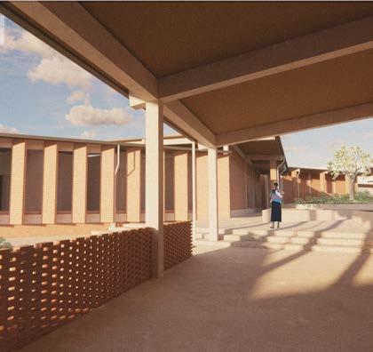
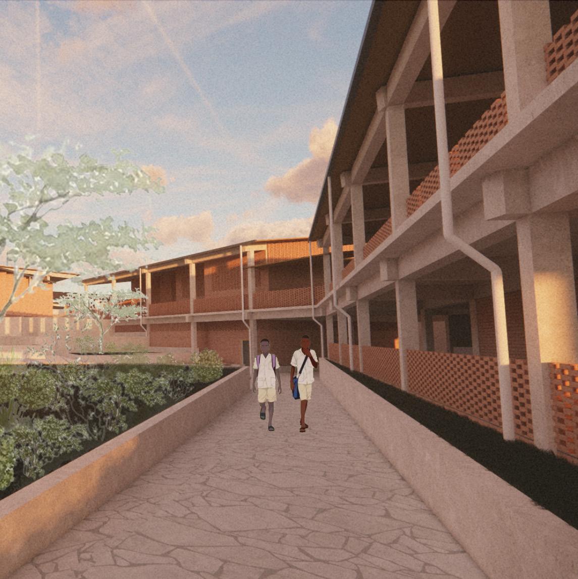
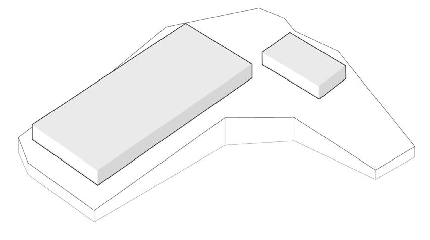
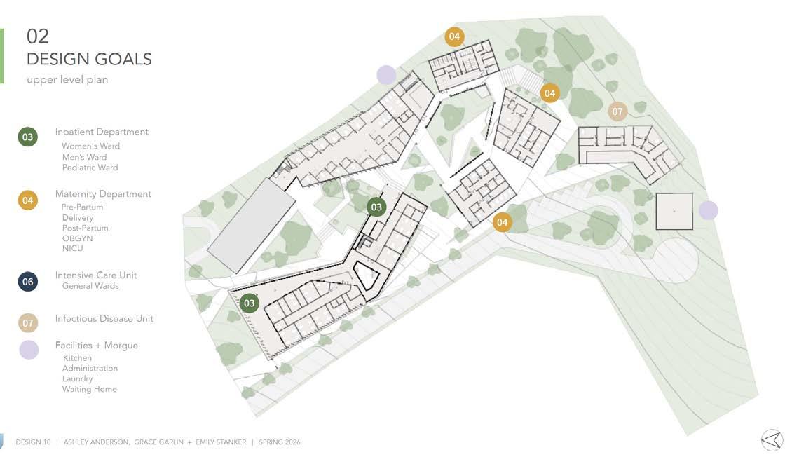
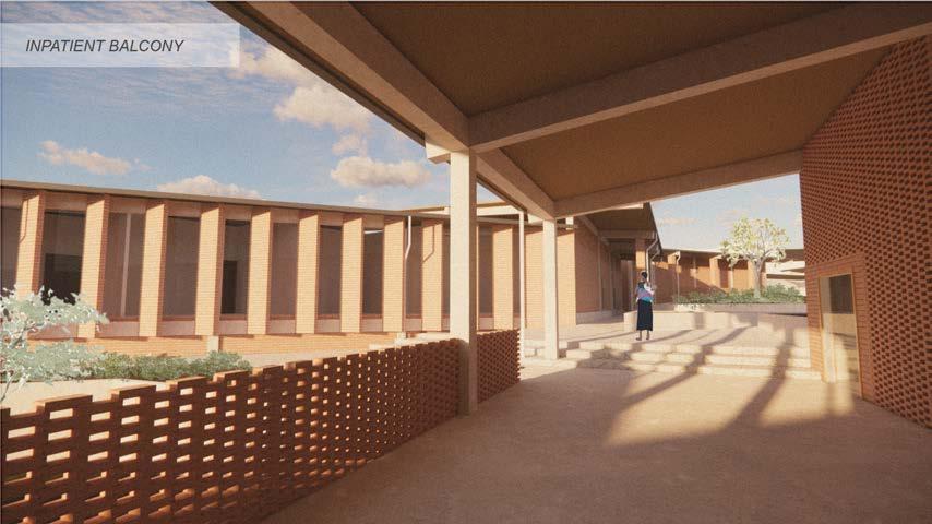
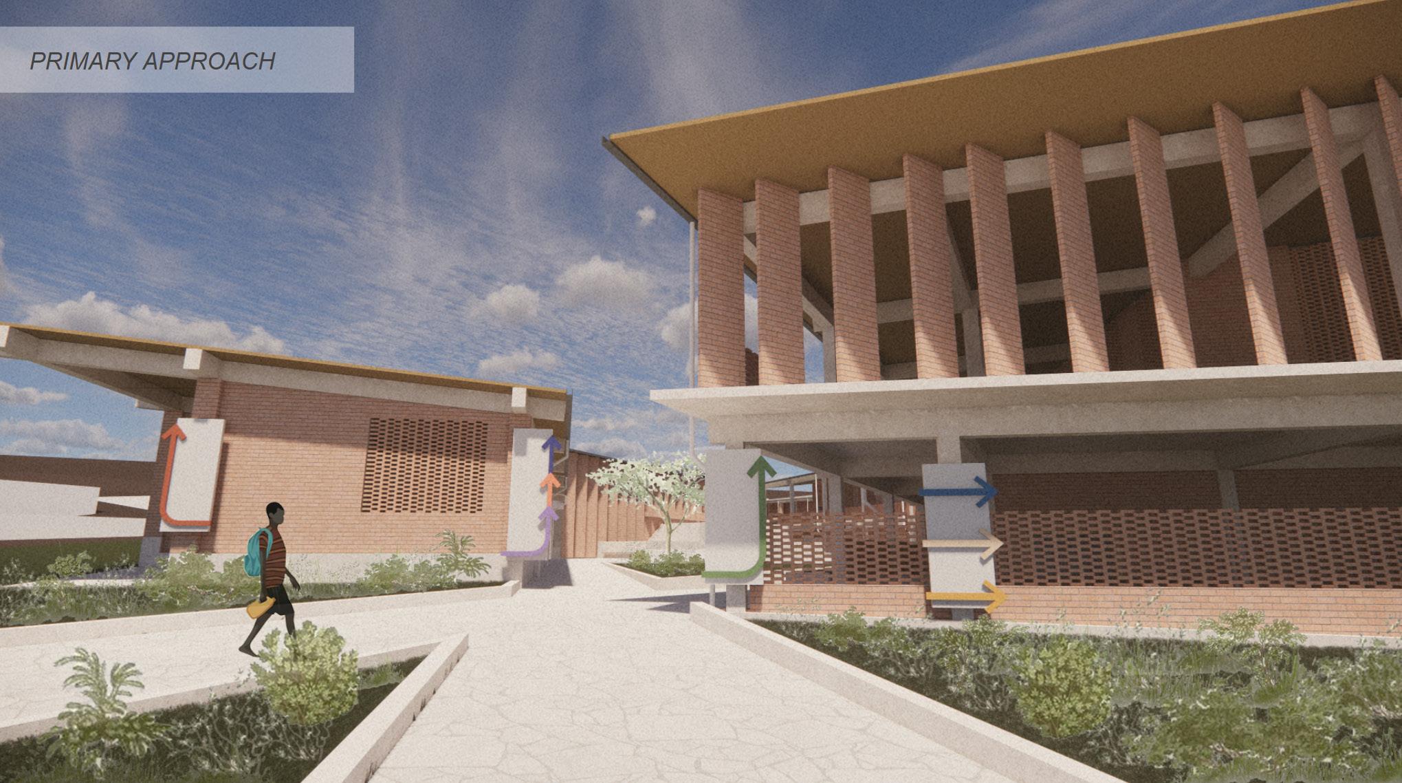
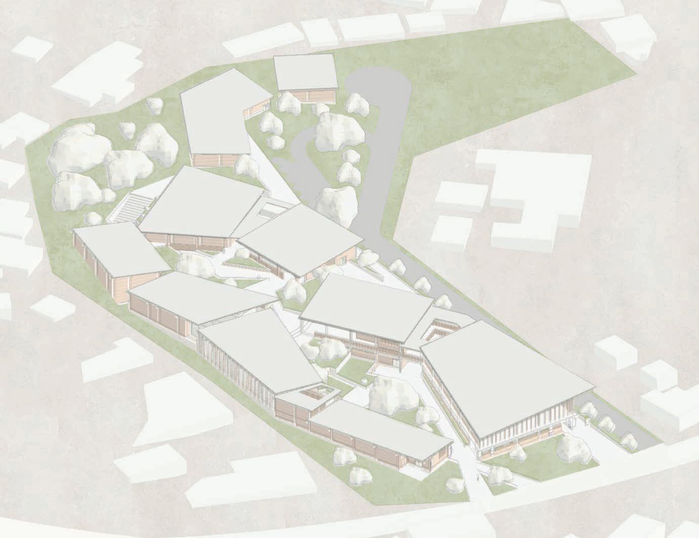
Ndirande Community Hospital
One of Africa’s greatest challenges is rapid urbanization. In Malawi, the population of 18 million is projectes to double to 36 million by 2050. As cities expand into dense informal settlements, hospitals are increasingly strained, especially with just one health center serving every 42,000 people.
Our Concept:
Our design for the Ndirande Community Hospital places a strong emphasis on the patient experience, particularly how people move through the site from the moment they arrive. Rather than treating circulation as something secondary, we approached it as a central design driver. We asked ourselves: How does someone who may be stressed, sick, or unfamiliar with hospitals intuitively know where to go?
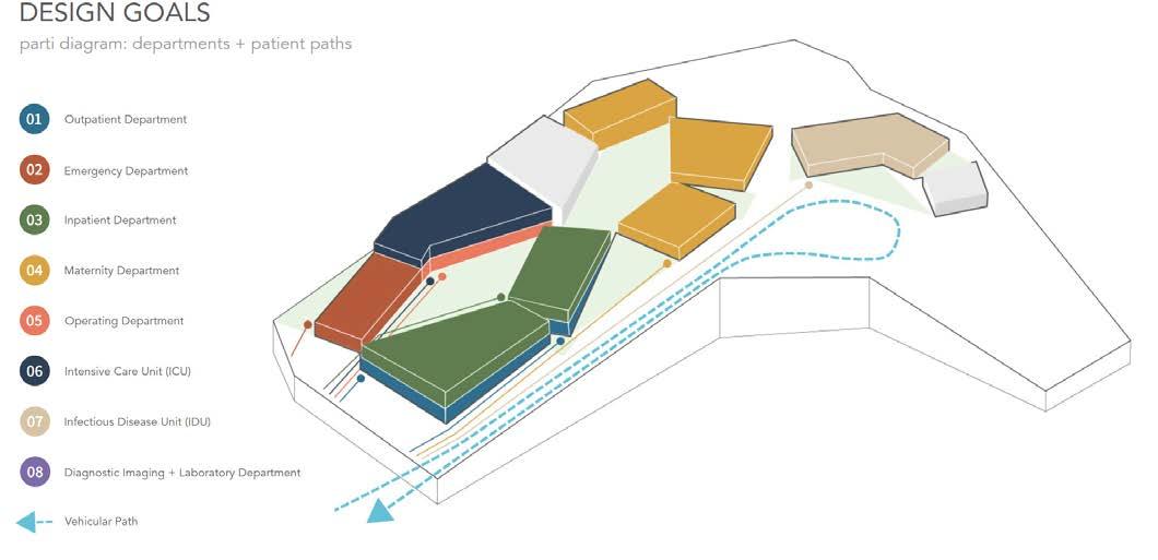
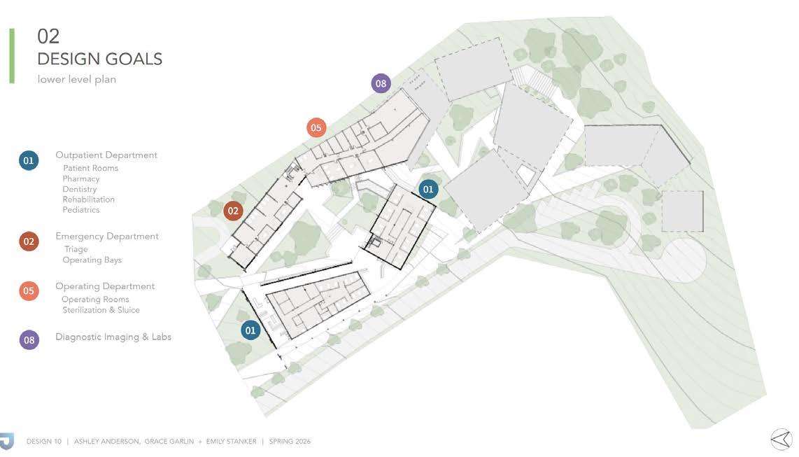
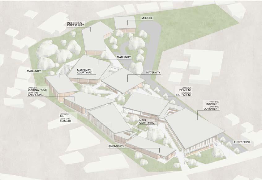
Programming:
The importance of departments lies in their ability to provide focused expertise, equipment, and resources to address specific aspects of patient health, while also ensuring continuity across the patient journey. It can be difficult for patients to navigate the programmatically rich building that is a hospital. By strategically organizing different hospital departments, the flow of the hospital is efficient for staff, patients, and guardians.
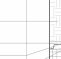
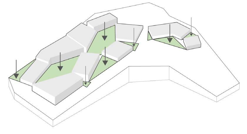
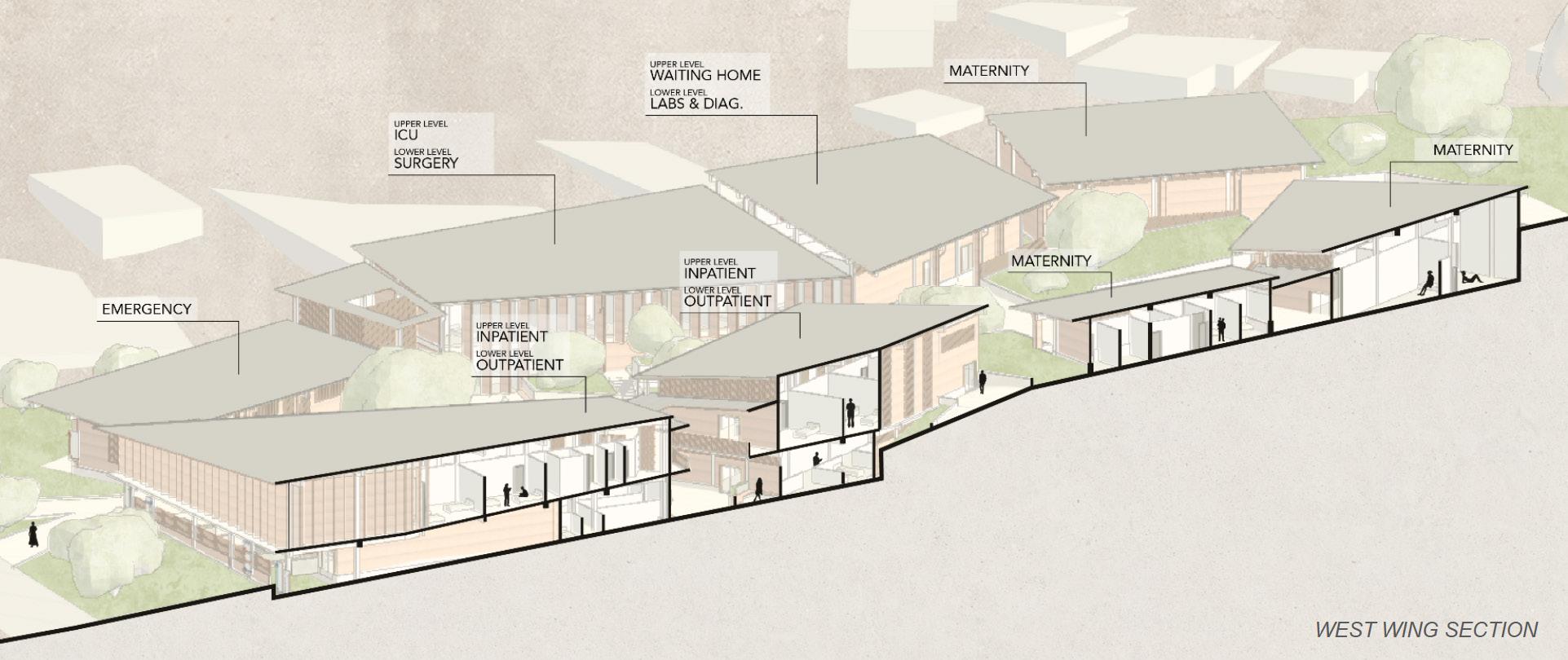
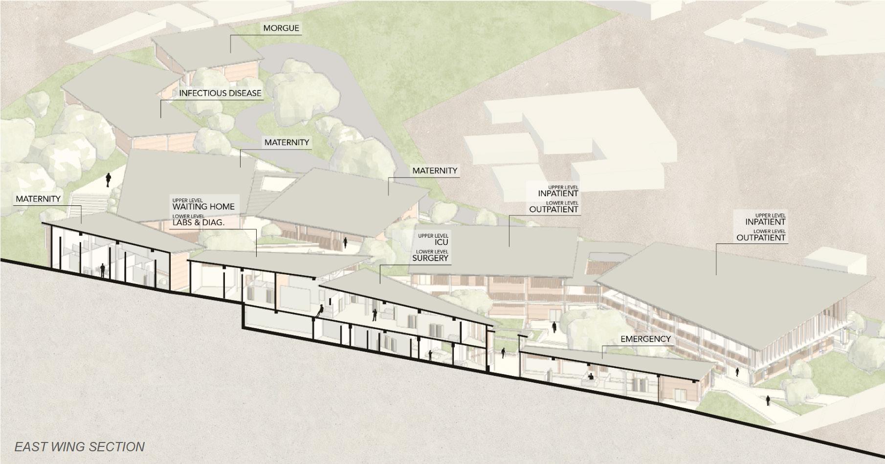
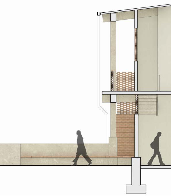
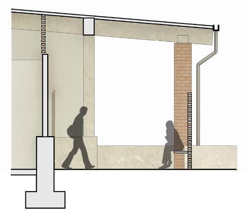
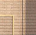
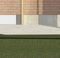
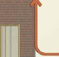
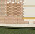
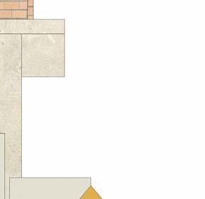
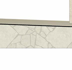
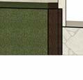
Throughout the project, the roofs are intentionally sloped towards the two central courtyards to support water management, with downspouts expressed along the facade. Outdoor seating is integrated across the site, with primary gathering areas located at the main entry points for outdoor waiting. Concrete is used as the primary structural material due to its ability to span long distances and its long-term durability. Additionally, the concrete establishes a strong visual and material connection to the planters and retaining walls used throughout the landscape
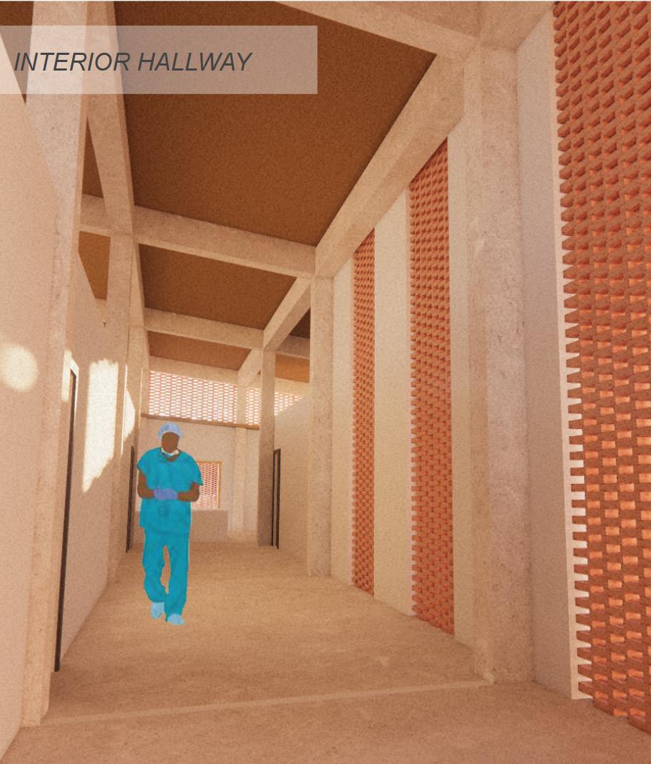
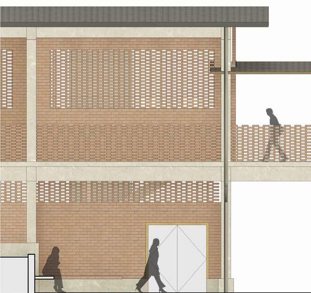
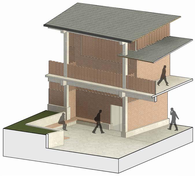
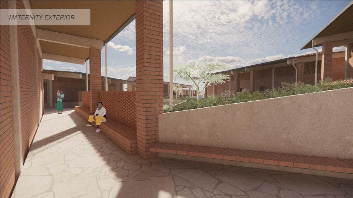
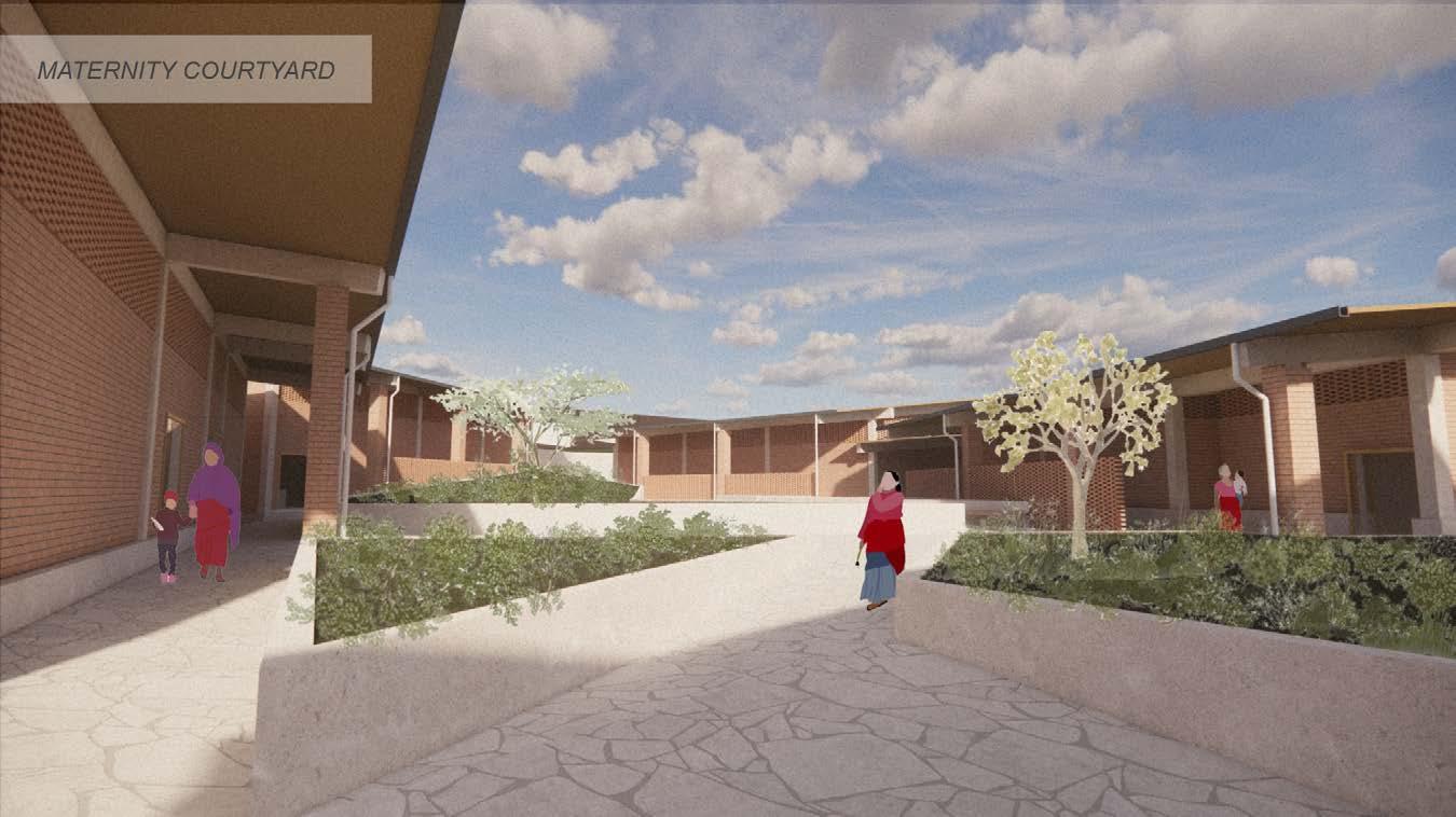
Maternity Department Entry:
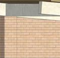
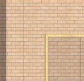
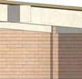
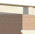
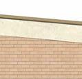
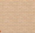
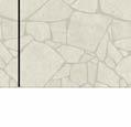
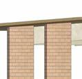
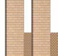
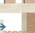
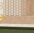
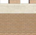
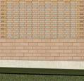
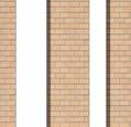
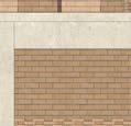
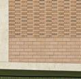
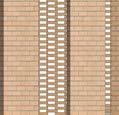
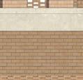
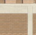
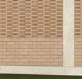
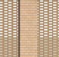
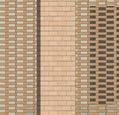
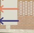
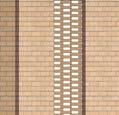
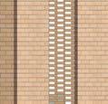
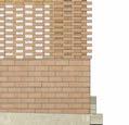
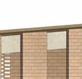
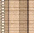
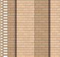
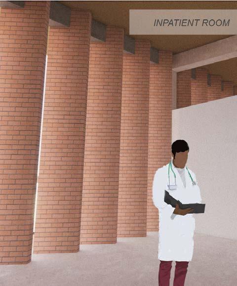
Covered walkways provide privacy along the maternity wing while also creating shaded seating areas for guardians and family members. Perforated brick allows for privacy, light, and ventilation throughout patient wards.
Wayfinding:
OUTPATIET DEPARTMENT
GENERAL
MATERNITY DEPARTMENT
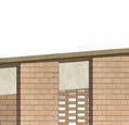
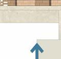
As patients arrive on the site, it is critical that they immediately understand where to go. Beyond the clearly defines directional pathways, signage is integrates across the front facade to reinforce intuitive circulation and guide patients and families to their required departments. By making wayfinding clear from the moment of entry, these signs help minimize confusion and reduce stress during what is often an already overwhelming experience.
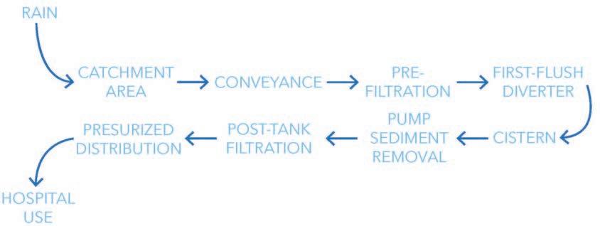
Water Management:
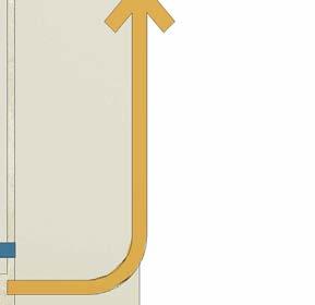
The wet seasons in Malawi — from November to April—deliver about 95% of the country’s annual rainfall, which makes it the critical window for water collection. We are developing a rainwater collection system where water is collected from roofs, guided and filtered into two separate underground cisterns, to then be distributed to the hospital for use.
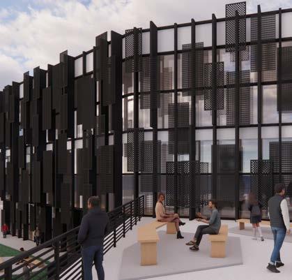
Northeast Philadelphia Mediatheque
Spring 2024
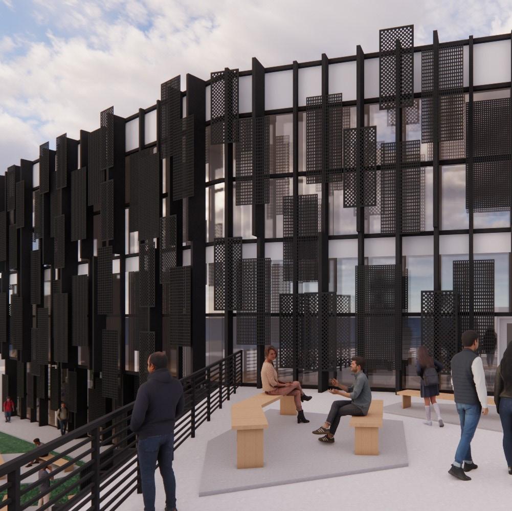
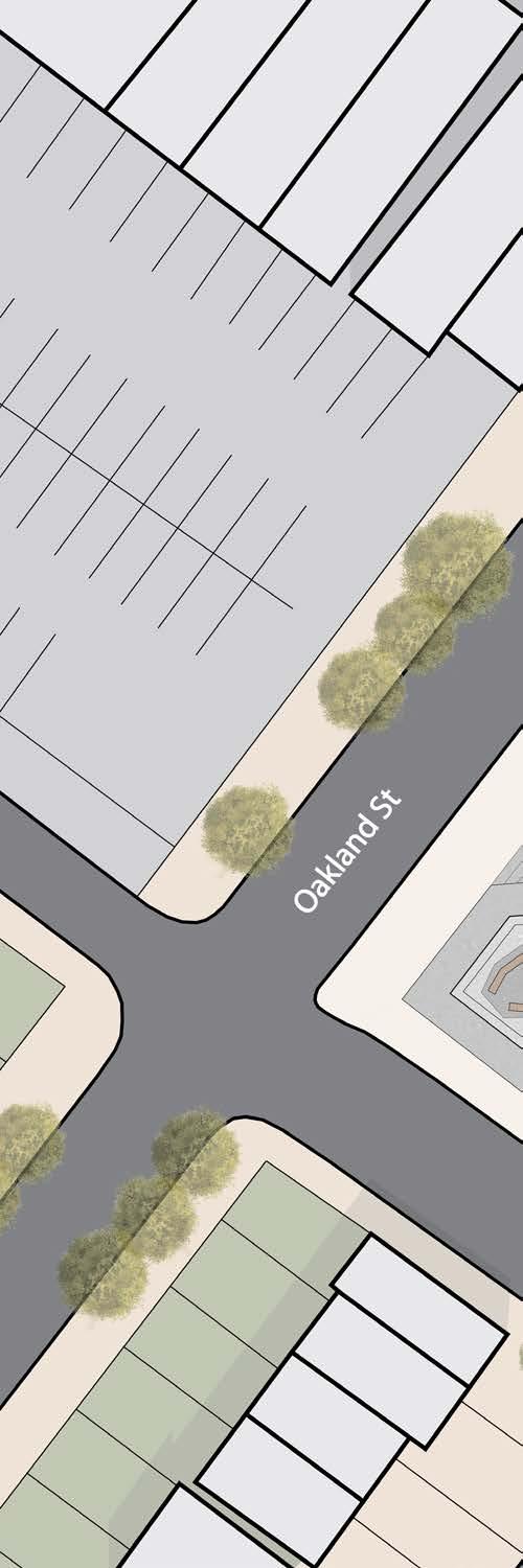
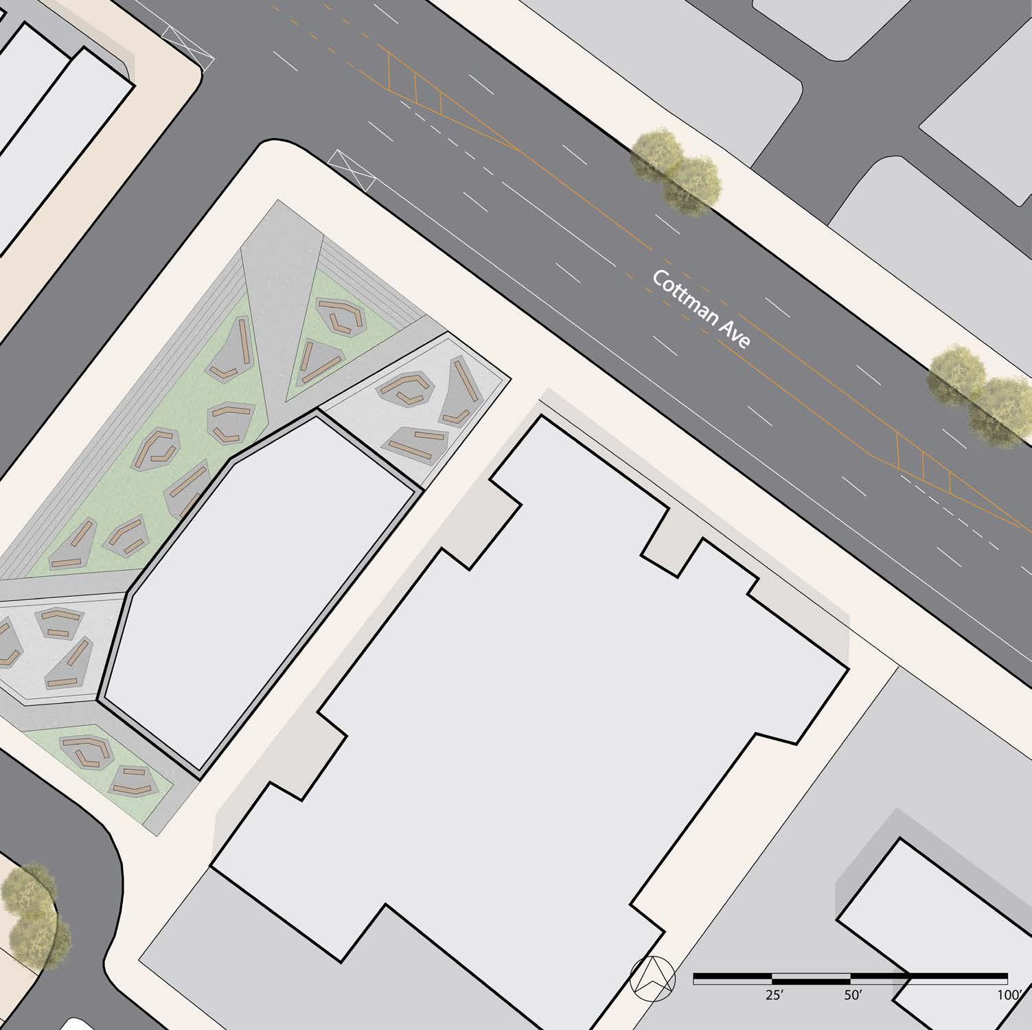
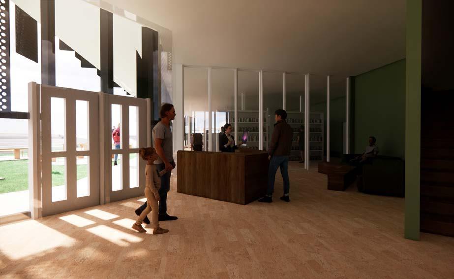
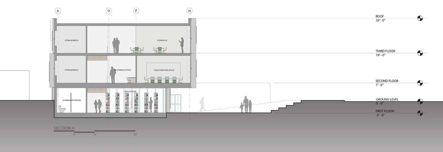
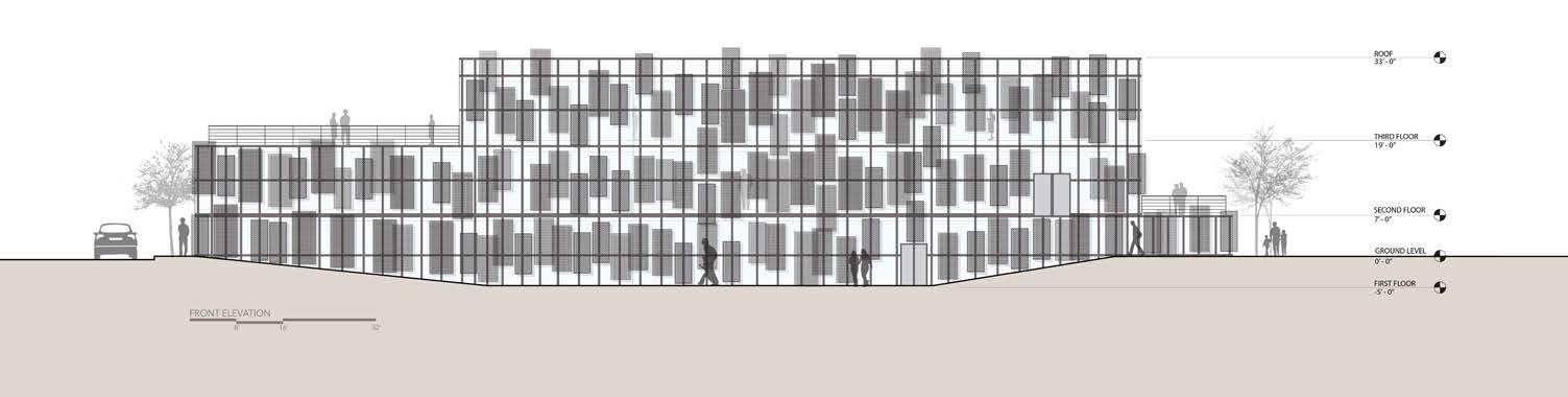
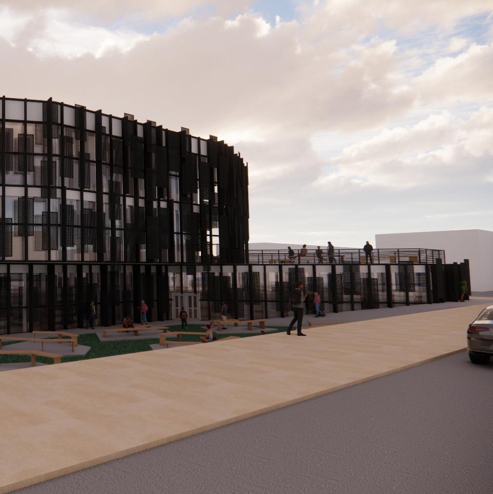
In this twelve week project I was tasked to design a multimedia library, located in Northeast Philadelphia. Through the action of pushing and pulling the facade, landscape, and massing, I designed a building which welcomes people from all sides of the site into a sade and comfortable multimedia hub.
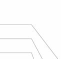
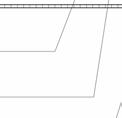
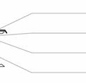
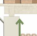
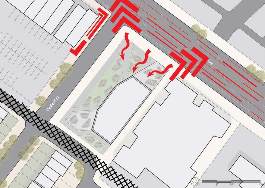
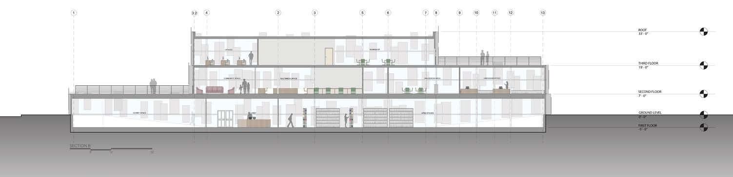
My initial reaction to the site was the feeling of a site boundary, splitting the commercial and residential parts of the site. Along with this, Cottman Avenue felt like an intimidating road due to the quick moving traffic and lack od crosswalks. These reactions can be seen as a challenge, however, they offer up an opportunity for me to design a building that welcomes people onto the site. This led me to developing the overall massing and shape for my project. I designed my building to pull back from that intersection to best welcome people onto this site. To support this I dropped my building 5 feet below grade and designed a building overhang to pull and direct people into the main entrance.
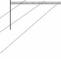
Site Reaction Diagram
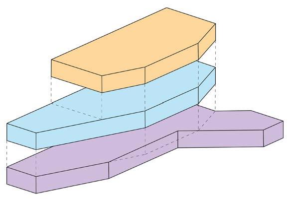
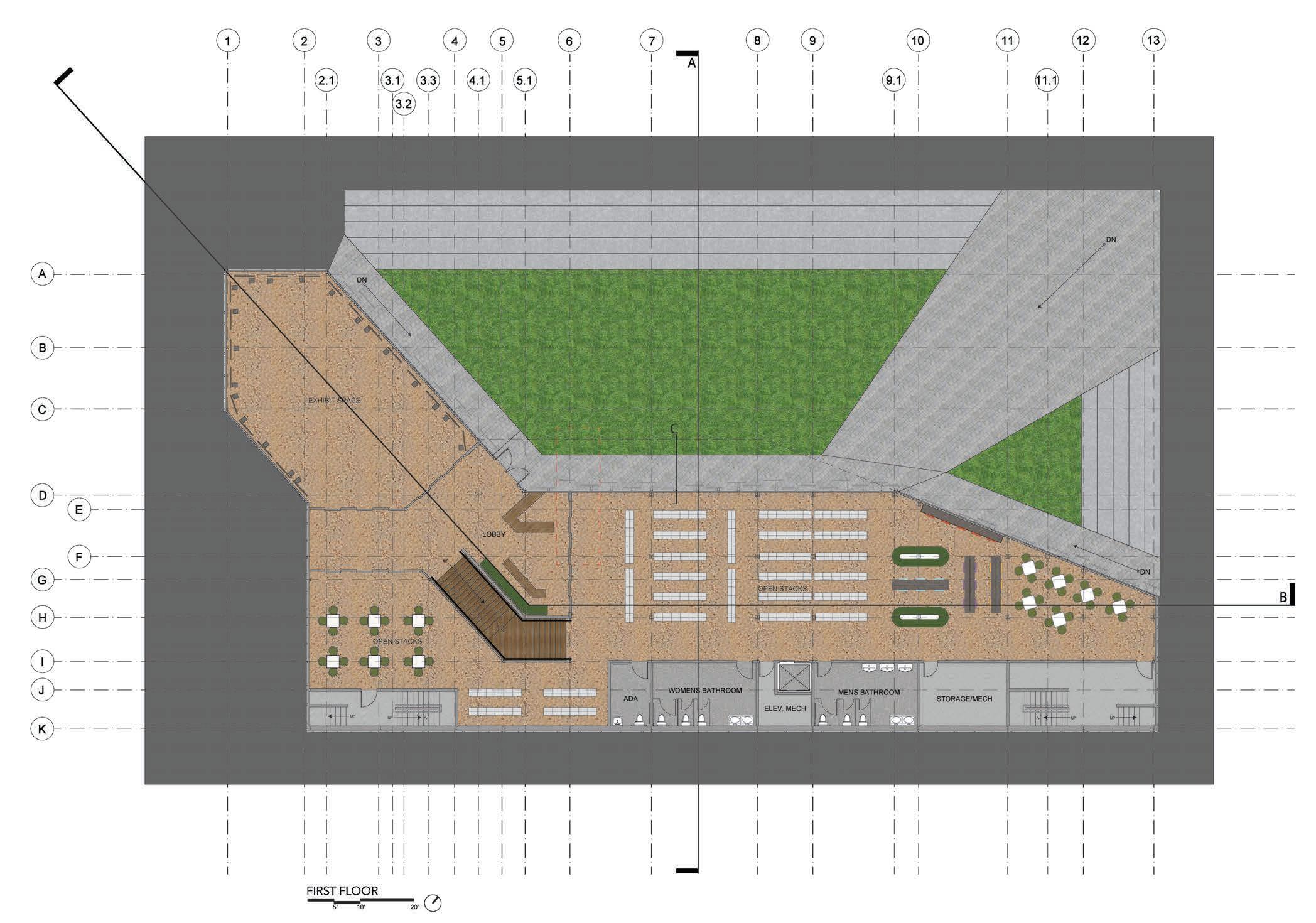
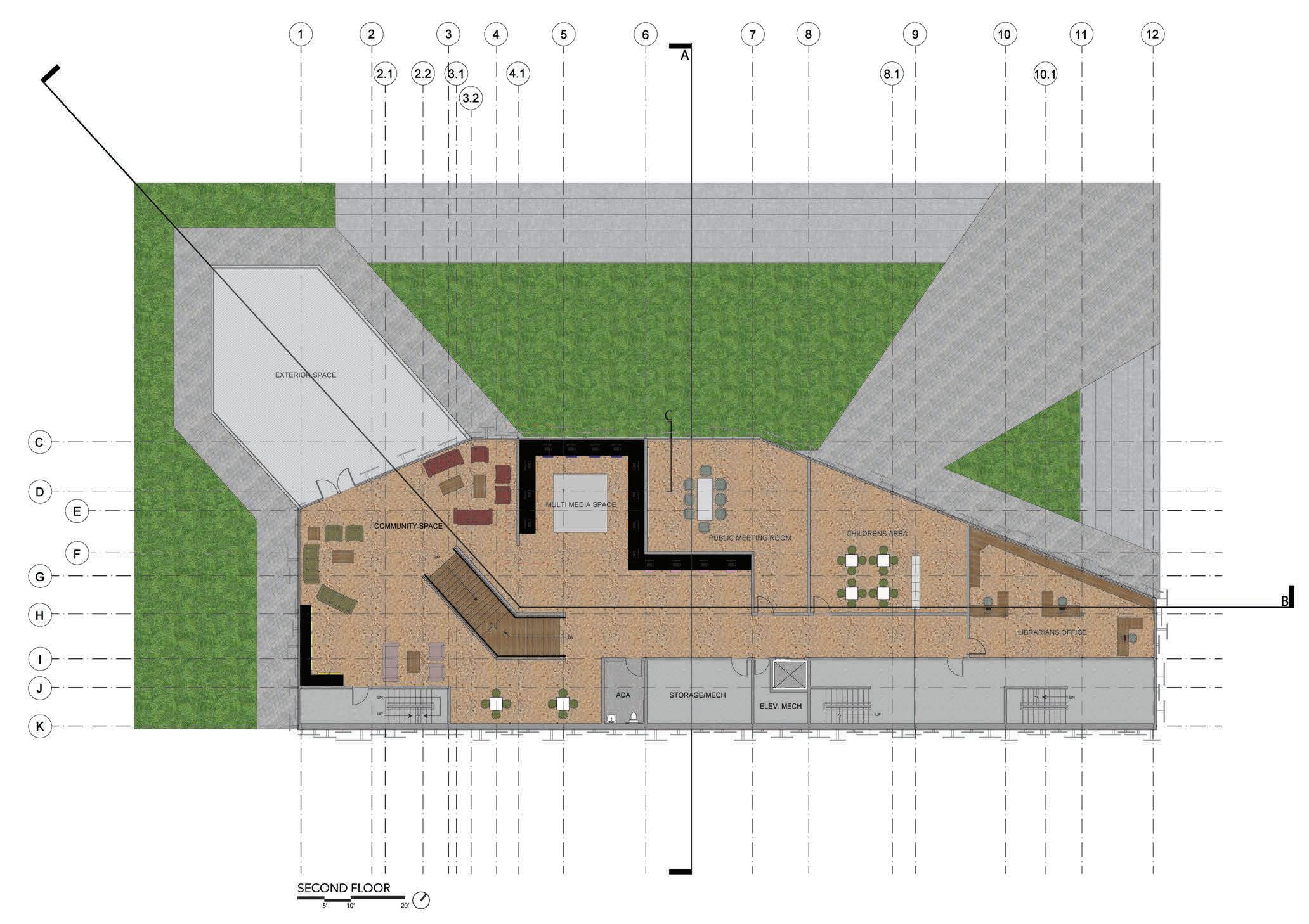
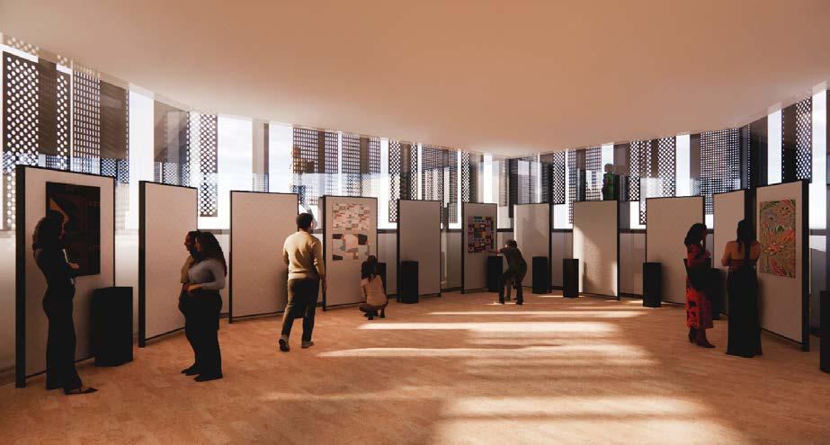
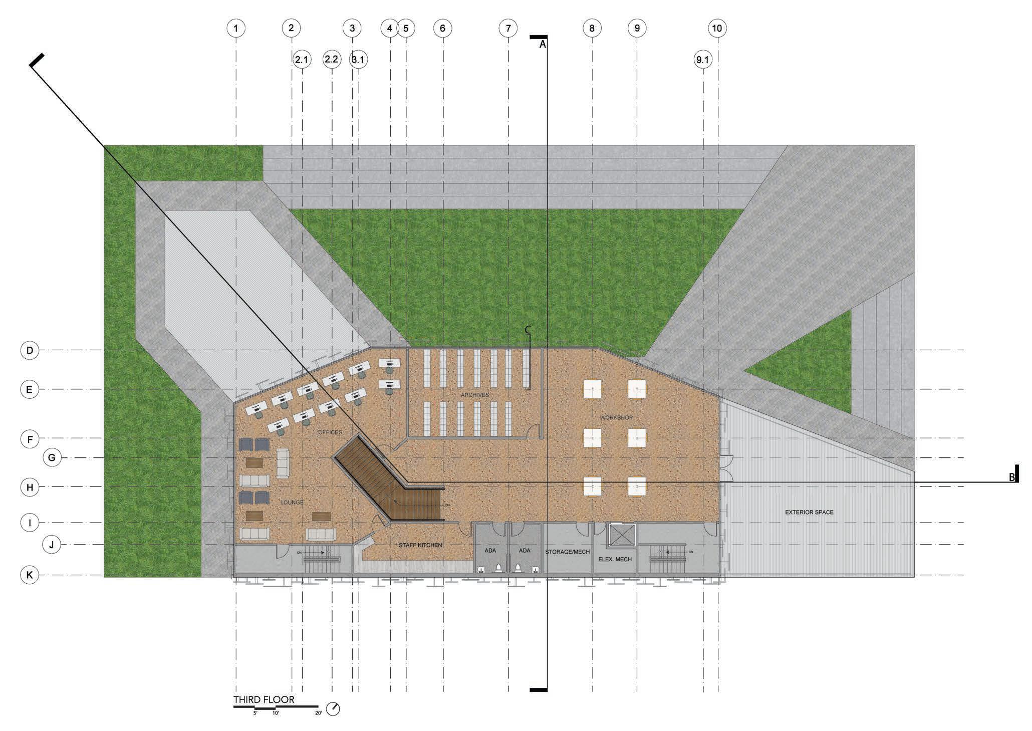
The design for my building is broken up into public spaces, supporting public spaces, and private spaces. To enter the building you process down one of the ramps and under the ten foot overhang. The first floor consists of the lobby, exhibit space, and open stacks, which are all separated from each other by sliding glass panels which allow all three spaces to feel connected. The second floor opens up to a large, open community space, which is connected to an exterior space that overlooks the site and lanscape. The third floor has a similar space on the other side of the building.
Exhibit Space Lobby Space
Open Stacks
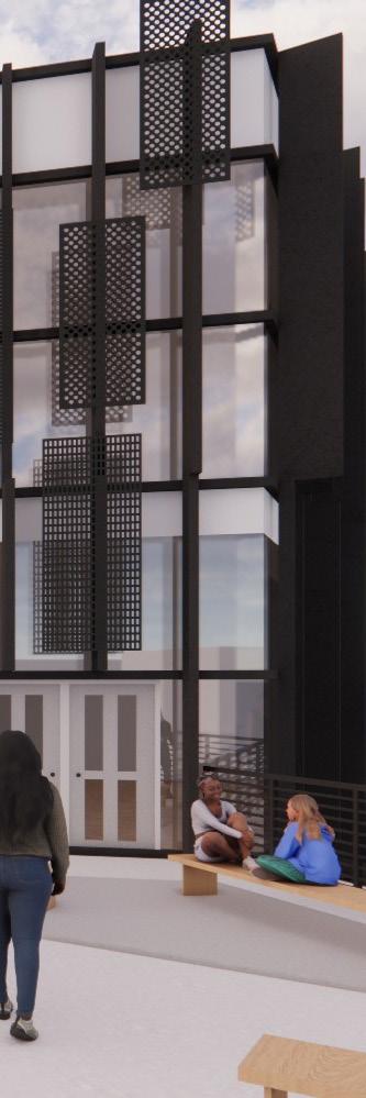
Building Entry
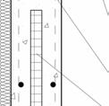
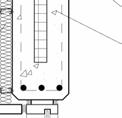
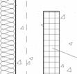
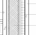
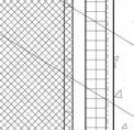
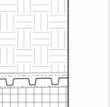
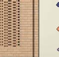
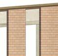
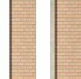
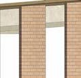
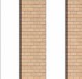
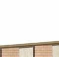
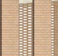
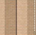
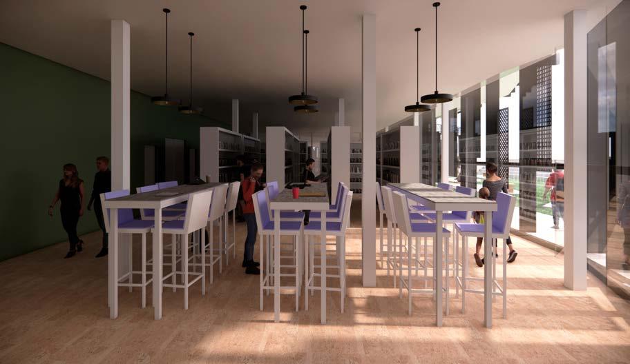
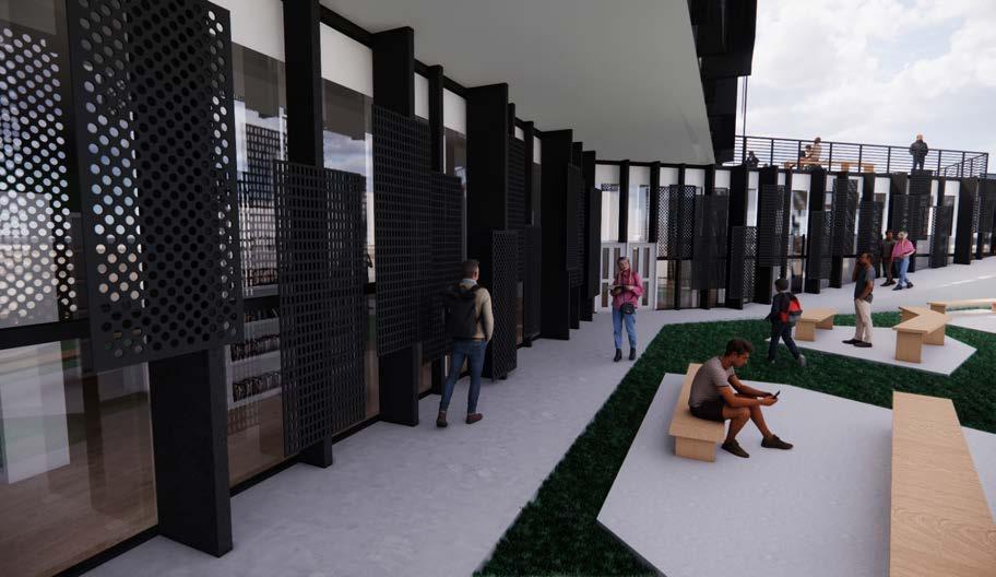
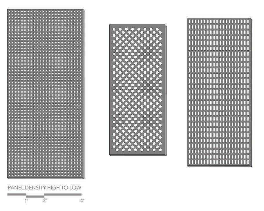
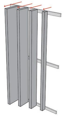
As I went into designing my facade I knew I wanted to emulate the ideas I presented in my massing, where I created depth though pushing and pulling elements. To do this I designed a mesh panel system that connects to a unique mullion system. The mech is designed in three different densities to regulate the amount of light that enters the space. This allowed me to strategically organize the panels on the facade to control the light based on the program that sits behind. Each vertical mullion along the facade pushes out at one of four different depths to also control light. These two systems work together to create a layered facade with beth to it through intentional pushing and pulling.
ARCHIVES
PUBLIC MEETING ROOM
OPEN STACKS
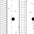
CAP FLASHING
BEVELED PLATE
C CHANNEL
WEATHER RESISTIVE BARRIER
RIGID INSULATION
TPO MEMBRANE
CANT STRIP
I BEAM MULLION CONNECTION
FLOORING
CONCRETE
METAL DECKING
FLOOR DECK
INSULATION
DROP CEILING
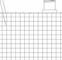
DOUBLE PANE GLASS
HORIZONTAL MULLION
VERTICAL EXTRUDED MULLION
MESH PANEL
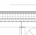
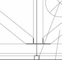
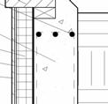
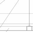
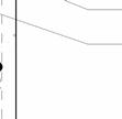
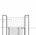
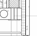
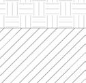
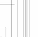
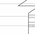
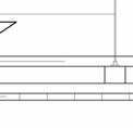
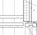
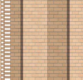
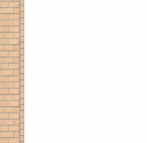
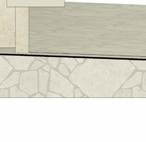
Moving into the technical design phase of this project I was required to first draft a wall section for an important part of my project. My wall section captures the ten foot overhang, the floor details, roof details, and connection details. Following the drafting of the wall section we were tasked with developing two details. I focused on the detail of the parapet roof and the detail of the connection of the mesh panels to the exturded veryical mullions.
PARAPET AND ROOF CONNECTION
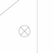
D2: MESH PANEL TO MULLION CONNECTION
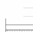
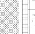
57'-0" WIDTH OF STAIRS: 44" REQ. - 60" PROVIDED
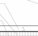
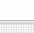
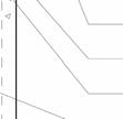
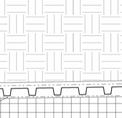
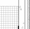
Life Safety & Fire Rated Assembly Exploration
NUMBER OF EXIT DOORS AT GROUND: 2 REQ. 4 PROVIDED MAX EGRESS DIST TO EXIT (GROUP B): 300 FT
COMMON PATH OF TRAVEL EGRESS PATH OF TRAVEL
EXIT 1: 46 OCC
46 OCC x 0.3" = 13.8" REQ.
72" PROVIDED
EXIT 2: 46 OCC
46 OCC x 0.3" = 13.8" REQ.
36" PROVIDED EXIT 3: 46 OCC
46 OCC x 0.3" = 13.8" REQ.
36" PROVIDED EXIT 4: 46 OCC
46 OCC x 0.3" = 13.8" REQ.
36" PROVIDED
FURTHEST TRAVEL DISTANCES:
PATH A TO EXIT 1 = 145'-4"
PATH B TO EXIT 1 = 155'-1"
PATH C TO EXIT 1 = 151'-7"
PATH D TO EXIT 2 = 157'-3"
DISTANCES BETWEEN EXITS:
EXIT 1 TO EXIT 2: 106'-0"
EXIT 1 TO EXIT 3: 110'-4"
EXIT 1 TO EXIT 4: 110'-4"
EXIT 2 TO EXIT 3: 69'-4"
EXIT 2 TO EXIT 4: 69'-4"
EXIT 3 TO EXIT 4: 73'-8"
EXIT 3
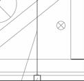
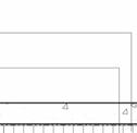
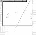
ASSIGNMENT 4: LIFE SAFETY
ASSIGNMENT 4: LIFE SAFETY
OCCUPANCY: 224 OCCUPANTS MIN. DISTANCE BETWEEN EXITS: 57'-0"
WIDTH OF STAIRS: 44" REQ. - 60" PROVIDED MAX EGRESS DIST TO EXIT (GROUP B): 300 FT
COMMON PATH OF TRAVEL
EGRESS PATH OF TRAVEL
EXIT 1: 112 OCC
112 OCC x 0.3" = 33.6" REQ. 36" PROVIDED
EXIT 2: 112 OCC
112 OCC x 0.3" = 33.6" REQ.
36" PROVIDED
TRAVEL DISTANCES:
A TO EXIT 2 = 109'-7"
B TO EXIT 2 = 118'-1"
DISTANCES BETWEEN EXITS: EXIT 1 TO EXIT 2: 73'-8"
ASSIGNMENT 4: LIFE SAFETY
For this project, I was required to design a two story office building with proper egress exits. From there I has to use the International Building Code (IBC) to calculate different aspects of the life safety code to ensture the building has the proper requirements.
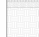
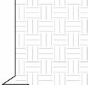
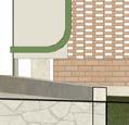
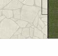
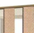
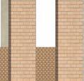
This project required us to learn more about fire rated assemplies as well as progressing skills for drafting details in recit. We were required to find three assemblies on the UL website and recreate them in Revit.
- Estimated range of acoustical performance is based on laboratory test data of similarly constructed assemblies
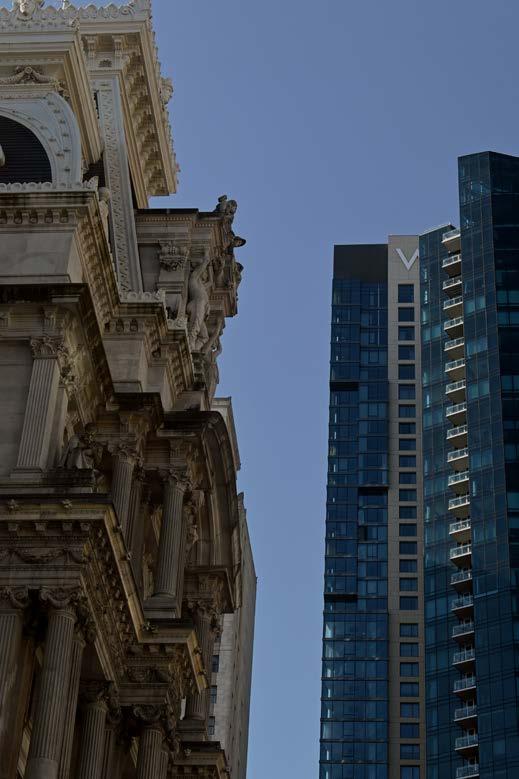
City Hall
Wilmington, DE
Wilmington, DE
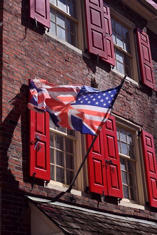
Philadelphia, PA
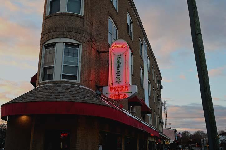
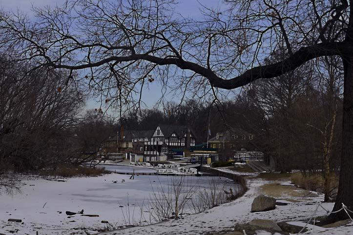
In this digital photography course I had the freedom to photograph anything I wanted. Throughout the semester I focused on landscape and architecture photography in Philadelphia, PA and Wilmington, DE.
Trolly Square
Trolly Square
Boathouse Row
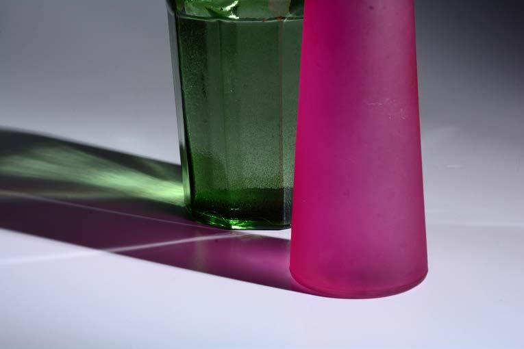
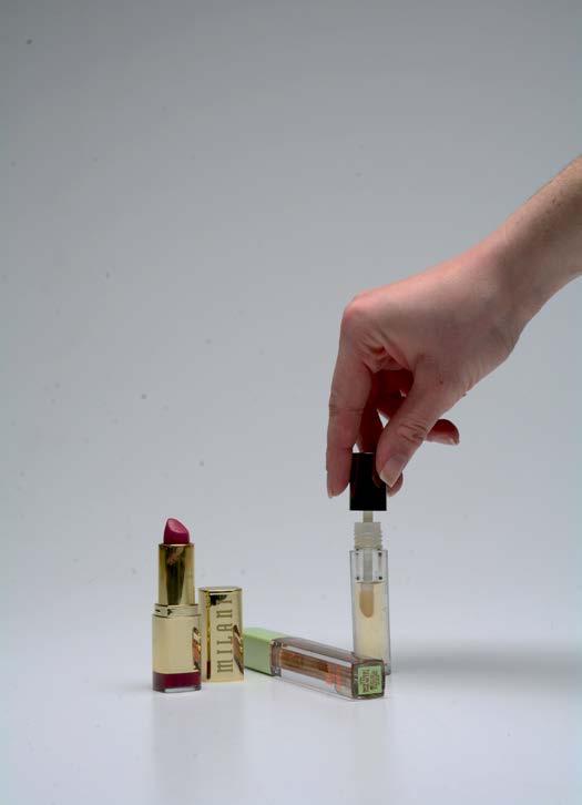
In addition to the digital photography course, I also took a studio photography course. In this class we explored how to photography different objects and people as well as different lighting techniques.