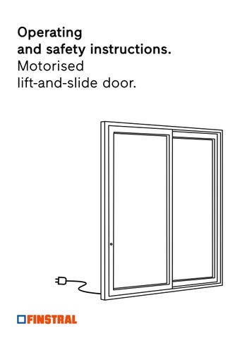
Operating and safety instructions.
Motorised lift-and-slide door.
3.3.1
![]()
3.3.1
1.1Originaloperatinginstructions
Theseinstructionsarepartoftheoriginaloperating instructions.Theoperatinginstructionsconsistofthe followingsections:
1.2Readtheinstructions
Theseinstructionsareanimportantdocumentand partoftheproduct.Onlythedefinedproceduresare safe.Personscanbeinjuredormaterialdamagecould occuriftheseinstructionsarenotobserved.
1.3Producer
SIEGENIA-AUBIKG Industriestraße1–3 57234Wilnsdorf Germany
1.4Targetgroup
Thisinformationisintendedforproducersof constructionelements,fittersandretrofitters. Producersofconstructionelementsareconsideredto beallthosewhoperformthefollowingactivities:
• fabricateSIEGENIAproductsinwindowelementsor doorelements
1.5Otherrelevantinformation
Refertothefollowingotherrelevantinformationprior toinstallation.
• SafetydatasheetinaccordancewithRegulation(EC) No.1907/2006,Article31
• DINISO2768-1:1991-06Generaltolerances
• assemblyinstructions
• operatingandserviceinstructions
Readandobservetheinstructionscompletelypriorto theinstallationoftheproduct.
Youcanfindtheaddressesofourworldwidelocations here: siegenia.com/company/locations
EntryintheCommercialRegister:
• Registrycourt:SiegenDistrictCourt
• Registernumber:HRA3741
Fittersandretrofittersincludeallpersonswhocarry outthefollowingactivities:
• SIEGENIAinstallandrepairproductsinabuilding project
• retrofitwindowelementsordoorelementswith SIEGENIAproducts
• Directive"Hardwareforwindowsandpatiodoors–Specifications/notesontheproductandonliability (VHBH)"oftheQualityAssociationforLocksand Fittings(GütegemeinschaftSchlösserundBeschläge e.V.)
guetegemeinschaft-schloss-beschlag.de/PruefenZertifizieren/Richtlinien/VHBH
• Assemblyinstructionstimber2.0 https://link.si/td/hshz001/0624
• Assemblyinstructionstimber4.0 https://link.si/td/hshz002/0624
1.6.1StatusLEDbatterypack
Symbol Meaning
LEDoff
LEDlightsup
LEDflashesin1colour
LEDflashesalternatelyin2colours
1.6.2Lightringoperatorpushbutton
Symbol Meaning Off Flashes Lightsup
DRIVEaxxentLSisadriveforoperatingmotorisedlift andslideelements.
• Theproductissuitableforinstallationinliftand slideelementsofthefollowingproductranges:
TimbersystemsHS2.0
TimbersystemsHS4.0
• Theproductissuitableforinstallationinliftand slideelementswiththeopeningtypeschemeA.
• Donotusetheproduct:
– inwindowsandpatiodoorsthatareintendedas escaperoutes
2.2.1Producersofconstructionelements
Weassumeandrequirethatproducersofconstruction elementspossessthefollowingknowledgeandskills:
• knowledgeoftheregulationsconcerning occupationalsafetyandaccidentprevention
• comprehensionoftechnicalcorrelationsbasedon thelatestscientificandtechnologicalknowledge
• knowledgeofprofessionalworksteps
• knowledgeoftheapplicablestandardsand directives
• knowledgeofapplicabletestingregulations
• knowledgeandskillsrelatingtotheprocessingof therespectivematerial(timber,PVC,aluminium)
• knowledgeandskillsrelatingtotheprofessionaluse oftools,machinesandsystemsfortheproduction ofwindowordoorelements
• knowledgeandskillsrelatingtotheprofessional fixingoftechnicalelements
• knowledgeofthefunctionaltestingandoperation ofwindowordoorelements
• knowledgeoftherequirementsofprofilesystem providers
–infire-ratedareas
– inconjunctionwithsmokeextractionsystems (SHEVS)
– inenvironmentswheretheaircontains aggressivecomponents
–inoutsideareas
• OnlyuseSIEGENIApowersuppliesthatareboth testedandcertifiedinaccordancewiththeEMC Directive.Achangeisnotpermissible.
Ifthewindowordoorelementsareequippedwith anelectromechanicaldriveorasensor,thefollowing knowledgeandskillsarealsopresumedandrequired:
• knowledgeandskillsrelatingtotheprofessional fabricationofelectricalcomponents
• knowledgeandskillsrelatingtothefollowingwork steps:
–connectingelectricalcomponents –puttingelectricalcomponentsintooperation –checkingthefunctionofelectricalcomponents
• knowledgeofthefollowing5safetyrules: –disconnect –securetopreventreconnection –ensuresystemisvoltage-free –earthandshort-circuit –coverorisolateproximateliveparts
SIEGENIAprovidestrainingtoenableyoutoacquire someoftheknowledgeandskillsneeded.Contactyour SIEGENIAsalesconsultantifthisisrequired.
Weassumeandrequirethatfittersandretrofitters possessthefollowingknowledgeandskills:
• knowledgeoftheregulationsconcerning occupationalsafetyandaccidentprevention
• comprehensionoftechnicalcorrelationsbasedon thelatestscientificandtechnologicalknowledge
• knowledgeofprofessionalworksteps
• knowledgeoftheapplicablestandardsand directives
• knowledgeandskillsrelatingtotheprofessionaluse ofelectricalandmechanicaltools
• knowledgeandskillsrelatingtotheprofessional fixingoftechnicalelements
• knowledgeandskillsrelatingtotheretrofittingof mechanicalsecuritytechnologyonwindowordoor elements
Riskofexplosionifthebatterypackhandledincorrectly Riskofexplosionduetoflammableliquidsorgases escaping.
• Donotusefaultyordefectivebatterypacks.
• Discontinueusingbatterypacksthatshowodouror heatdevelopment.
• Discontinueusingbatterypacksthatshowdeficient poweroutput.
• Discontinueusingbatterypacksthatshow discolourationsorthermaldeformations.
• Donotpierce,deformordismantlethebattery pack.
Ifthewindowordoorelementsareequippedwith anelectromechanicaldriveorasensor,thefollowing knowledgeandskillsarealsopresumedandrequired:
• knowledgeandskillsrelatingtotheprofessional fabricationofelectricalcomponents
• knowledgeandskillsrelatingtothefollowingwork steps:
–connectingelectricalcomponents –puttingelectricalcomponentsintooperation –checkingthefunctionofelectricalcomponents
• knowledgeofthefollowing5safetyrules: –disconnect –securetopreventreconnection –ensuresystemisvoltage-free –earthandshort-circuit –coverorisolateproximateliveparts
SIEGENIAprovidestrainingtoenableyoutoacquire someoftheknowledgeandskillsneeded.Contactyour SIEGENIAsalesconsultantifthisisrequired.
Dangerduetosashmovementdespiteshuttingdown the230Vpowersupply
Evenaftershuttingthe230Vpowersupplydownthe slidingelementcontinuestomoveelectricallybecause ofthechargedbatterypacks.
Thelabelsservetoidentifytheproduct. Thelabelscanbefoundonthebatterypack,thegear andtheslidedrive.
SIEGENIA-AUBI KG, Am Fohlengarten 6, D-54411 Hermeskeil
SIEGENIA-AUBI Ltd., Richardson Way-Cross Point, CoventryCV2 2TA
AC 230V, 50 Hz, 30W IP20 max. 60N/max. continuous cycles 5 251 - 400kg -> Vmax = 110 mm/s
4698540 42/2025 Serien-Nr.: ax000248
GETRIEBE STD MO LS GR.2
659408 Länge 1.788,0 mm
4698540 42/2025 Serien-Nr.: ax000248
Schiebeantrieb AXXENT LS 603503
4698540 42/2025 Serien-Nr.: ax000248

3.3.1StatusindicatorandmenubuttononthebatterypackaxxentLS
1 Statusindicator(multi-colourLED)
2 Menubutton(multi-colourLED)
Buttonpressed Timespan
Shortpress 0–1second
Longpress 3seconds
Constantpress 8seconds
• Functioncontrol
• Displayofthemenu
• Wakingthebatterypack
• Changeofthemenuitemswithinthemenulevel1and2
3.3.2OperatorpushbuttonaxxentLS
1 Operatingbutton
2 Lightring
• Shortpress(0–1second)
• Longpress(1–3seconds)
• Constantpress(>3seconds)
• Sashloweredandlocked
• Sashopenedandstopped
• Sashmoves
• Sashinlockingposition,butnotlowered
• Sashraises
• Sashlowers
3.4.1Functionsoftheoperatorpushbutton
Pairingmode
• Forconnectingtheliftdriveandslidedrivetothe batterypack.
• Forcontrollingtheliftdrivewithoutslidedrive present.
• Thelongpressstartsthepairingprocess.
• Thebatterypackswitchesitselfoffafter 10minutes:
–aslongasamainssupplyisnotconnected; –whenasashisstandingopen;
– Thiswaythebatterypackisprotectedagainst discharge.
Processormode
• Forperformingthereferencerunandteach-inrun.
• Theshortpressstartsthereferencerun.
• Acousticsignalssoundduringtheshortpressofthe operatorpushbutton.
• Thelongpresstartstheteach-inrun.
Operatormode
• Fullrangeoffunctionsfortheoperationattheend customer’slocation.
• Acousticsignalsnolongersoundduringtheshort pressoftheoperatorpushbutton.
Dependingonthemode,thebatterypackwillswitch ofautomatically.Anascendinganddescendingtone sequenceisemitted.
Prerequisite: theslidingsashisnotinthecharging contacts(ifvoltageispresent,thenthebatterypack doesnotswitchitselfoffautomatically).
• inthepairingmodeafter10minutes(afterthelast action;thisincludespressingonthemenubuttonor theoperatorpushbutton)
• intheprocessormodeafter30minutes(afterthe lastaction;thisincludespressingonthemenu buttonortheoperatorpushbutton)
• Whenretractingintothechargingcontact(start ofthecharging)andwhenextendingfromthe chargingcontact(endofthecharging)anacoustic signalsoundsatthemainssupplyconnected.
• Thebatterypackswitchesitselfoffafter 30minutes:
–aslongasamainssupplyisnotconnected; –whenasashisstandingopen;
– Thiswaythebatterypackisprotectedagainst discharge.
• Theintermediatepositionisreachedusingthelong press.
• Thelongpressisconfirmedwithanacousticsignal.
• intheoperatormodenotime-dependentshutdown occurs
• inallmodestheoptiontoswitchoffmanuallyvia themenubutton
Thebatterypackiswokenbypressingonthemenu button.Anascendingtonesequenceisemittedand theLEDsonthestatusindicatorandonthemenu buttonlightup.TheLEDsswitchoffautomaticallyafter 2minutes.
3.4.3Queryingthechargestatusofthebatterypack
• Shortpressonthemenubutton:>thestatusLEDandthemenubuttonlightup
• Shortpressonthemenubutton
• Thechargestatusisdisplayedfor10secondsonthestatus-LED
• ThemenubuttonLEDflasheswhitewhilethestatusLEDdisplaysthechargestatus
Chargestatus
100%–40%
39%–20%
19%–0%
Displaystatus-LED
ThestatusLEDlightsupgreen
ThestatusLEDlightsupyellow
ThestatusLEDlightsupred
Thestatusmonitoringispermanentlycarriedout.This meansthattheproductisalwaysinactiveoperating status.Thissafetyfunctionmeansthatthereisno standbystatusforthepresentdevice.Thestatus monitoringdetectsiftheslidingsashisopened fromthelockedstatuswithoutdriveactivity.This correspondstoanunauthorisedopening,forwhichan alarmtoneisemitted.
• Prerequisite: Theslidedriveisintheprocessor modeorintheoperatormode
• Whenthefullypairedslidingsashismanually movedfromthelockedposition,analarmtoneis emittedfor1minute
• Turningtheemergencyoperatingkeyalsotriggers thealarmtone
Deactivatethealarmtone:
• Intheprocessormodethealarmtoneiscancelled byshortpressontheoperatorpushbutton
• Intheopertormodethealarmtonecannotbe cancelleddirectly;thealarmtoneisemittedfor 1minute
3.4.5Jamprotection
• Assoonasthepathoftheslidingsashbecomes blocked,(e.g.duetoanobstacleorbecauseitis stuck),itstops
• 3shortacousticwarningsignalssound
3.5.1Menulevelprinciple
• TheoperatorpushbuttonLEDchangesforafew secondsfromcontinuouslightingtoflashing
• Theslidingsashtravels100mmintheopposite directionandthencomestoafinalstop
Buttonpressed
Description
• Everypressofabuttonisconfirmedbyanacousticsignal. Shortpress Thebatterypackiswoken. constantpress(selection) Selectmenulevel1. Theselectionalwaysstartswithamagentamenuitem. longpress Changethedesiredmenuitemtomenulevel2. shortpress Changethemenuitemswithinthemenulevel. longpress(confirmation) Saveorexecutethedesiredmenuitem.
Leavingamenulevelwithoutactivatingasetting:
• Waittime30seconds
• Donotpressthemenubuttonagain
Volumeoftheinformationtones
LEDbrightnessoftheoperatorpushbutton
Thisfunctionisnotallocated.
LEDmenulevel1
Parallelliftandslide
ON(defaultsetting) OFF
Silentmode(softerandslower) ON
OFF(defaultsetting)
Deviceservices
Restartthedevice
Resetallmenuitemstodefault setting
Deactivatebatterypack
Saveintermediateposition
• Movesashtoanyposition
• Selectmenuitemandsave position
Activatereference,measuringand teach-inrun
Activatefabricatormode
Thefollowingmenulevelscanonlybeselectedunderoneofthefollowingconditions(inprocessormodefor5hours,in operatormodefor30minutes):
• Disconnecttheslidedrivefromthebatterypack,or
• theelementmustbeintheclosedandlockedstatefor>1minute.Thendisconnectthepowersupply(230V)for>10 seconds.
Systemservices
Coupledevices
Disconnectdevices
Thisfunctionisnotallocated.
Resettingtothefactorysetting
Thisfunctionisnotallocated.
3.6.1Hardwaresizerange
Sizerangessashheight(FH)withstandardgear
Gearsize withrunningrail0mm: sashheight(mm) withrunningrail5mm: sashheight(mm) withrunningrail 15mm:sashheight (mm) Sashwidth(mm)
Size1 1950–2145 1950–2150 1950–2160
Size2 2146–2345 2151–2350 2161–2360
Size3 2346–2545 2351–2550 2361–2560
Size4 2546–2745 2551–2750 2561–2760
Size5 2746–2945 2751–2950 2761–2960
Size6 2946–3145 2951–3150 2961–3160
3.6.2Drillingdimensionsfortheoperatorpushbutton
T Positionofthebuttonhole
3.6.3Millingdimensionsforthebatterypackandtheliftdrive
A Detailmillinggearbox/gearmotor
B Detailbuttonhole
T Positionofthebuttonhole
Dimensionsinmmaftersurfacetreatment
3.6.4Drillingdimensionsforthecableconnection
Dimensionsinmmaftersurfacetreatment
3.6.8Drillingdimensionsforthecouplingshoe
3.6.9Drillingdimensionforthechargingcable
Dimensionsinmmaftersurfacetreatment
3.7.1Connectingtheliftandslideelementtotheelectricitygrid
• CONNECTTHEDRIVEAXXENTLSTO24VOLTSONLY
• Donotroutecablewithdatalinesandnotoncableracks,inceilingvoidsandinsharedcableductsinpublicbuildings/ high-risebuildings
• ExtensionofthelineofthechargingcontactaxxentLS,supplied,onlyfeasiblewithalinewithwirecross-sectionofmin. 1.5mm2
• Totallinelengthforthetophatrailpowersupply:100m
• Totallinelengthforthebuilt-inpowersupply:50m
• Minimuminstallationdepthoftheinstallationsocketforthebuilt-inpowersupply:60mm
1 Powersupply 2 +24VDC(red) 3 -GND(black) 4 DRIVEaxxentLS
3.7.2Functioncontrolofthechargingcontact
Requirements:
• Theprocessormode(cf.chapter"Howitworks")isactive.
• Theliftandslideelementisconnectedtoapowersupply.
1. TIP: Movetheslidingsashinandoutofthe chargingpositionbyhand.
→ Anacousticsignalsoundswhenretractingfrom theslidingsash.
ThestatusLEDlightsupmagentafor2seconds.
→ Anacousticsignalsoundswhenextendingfrom theslidingsash.
ThestatusLEDlightsupredfor2seconds.
→ Thechargingcontactisinthecorrectposition.
→ Thepowerconnectionismadecorrectly.
3.7.3Chargingasinglebatterypack
Forvariousreasonsitmaybenecessarytochargethe batterypackbeforefurtheruse.Onereasonis:
• Thechargecapacityofthebatterypackisnot sufficientforthecommissioning(thestatusLED lightsupyelloworred).
Tochargethesinglebatterypackusethepower packcorrectorPZMR0050andthechargeadapter PZMR0070.
3.7.4Useofthepowerpackcorrector
ThepowerpackcorrectorPZMR0050isintendedfor provisionalandtransitionalpowersupplyonly.
3.8Technicalspecifications
TechnicalspecificationsDRIVEaxxentLS
Supplyvoltage 24VDC
Operatingcurrentstandby/standby nonexistent
Reversepolarityprotection existent
Operatingtemperaturerange
Permissibleairhumidity(noncondensing) 20%–80%
Protectiontype IP20
Protectionclass 0,1,2,3
Corrosionclass(inaccordancewithDINEN1670) 1
Durabilityclass(inaccordancewithEN13126-16) H3,20000cycles
Maximumdisplacementforce 60N
Openingspeed (dynamicimpactforcesinaccordancewitDINEN16005)
Technicalspecificationsbatterypack
Authorisationnumberofthelithiumcells
<250kg:140mm/sec. 251–400kg:110mm/sec.
Jigcouplingshoetimber
Jigcouplingshoetimberslim
Insertionaidcouplingshoe
Jigbuttonpanelemergency release
Screwsandfixingpincouplingshoe PAMR0010-...
Screw-insleevesM5andfixingpin couplingshoe onlyforprofilesystemslim PAMR0020-...
Screw-insleevesM5 onlyforprofilesystemslim PAMR0030-...
Buttonpanelemergencyrelease PAMR0210-...
Jigconnectionlinecoupling shoe
Throughholeconnectionlinecoupling shoe PAMR0200-...
JigsocketsCUBEcover SocketsCUBEcover PABB0490-...
Screwdriverforscrew-in sleeveM5
Tooling
Hexagonwrenchwithballhead4mm
Insertionofscrew-insleeveforprofile systemslim PABB0740-...
Intendeduse
Fixingtheclampingpieces
Slottedscrewdriver7mm
DrillØ3mm
Ø4mmdrill
Ø8mmdrill
Ø10mmdrill
Ø15mmdrill
HolesawØ20mm
Tensioningthefillingpieces
Holefixingscrewcouplingshoe
Holesforgear
Holefixingpincouplingshoe
Holessocketsbuttons
Throughholelinecouplingshoe
Emergencyreleasebutton
1.Milltheslidingsashandframeaccordingtothe machiningdimensions(seepage20).
2.Removeanysplintersfromroutedpockets.
3.Beforeinstallingtheproduct,checkthe dimensionalaccuracyoftheslidingsashandthe frame.Donotinstalltheproductintheeventof warpingordamage.
Dimensionaltolerancesforframesandsashes: ±1mm
4.3.1Overviewoftheassemblysequence Properadjustmentoftheguidingrailintheframe
• Positiontheguidingrailcorrectly
• AllassemblystepsareshownonanelementDINLH
4.Checktheproductfordamage.Donotinstallthe productifitisbentordamaged.
5.Routethepowersupplycabletothedriveswithout kinksandwithoutcrushing.
• CarryoutallassemblystepsmirroredincaseofassemblyDINRH
Properlypushingthecomponentsintotheassemblyopeningsoftheguidingrail
Pushingthecomponentsintoassemblyopening1:
Pushingthecomponentintoassemblyopening2:
4.3.2Assemblyofframepartsintheguidingrail
1.GuidethecablefromthechargingcontactthroughthesealingpieceSC002. PullexcesscableoutwardthroughthesealingpieceSC002.
2.Insertthefrontguideintothelockingsideoftheguidingrail.
3.Insertthecatchintotheguidingrailfromthefixedsashside.
4.Positiontheguidingrailintheframecorrectlyandscrewfirmly.
5.Inserttheclampingpiecesintotheassemblyopening1andpushinthedirectionofthefixedsashside.
6.Fixtheouterclampingpieceattheendoftheguidingrail.
7.(1)Inserttheslidedriveintotheassemblyopening1andpushalittleinthedirectionofthefixedsashside.(2) Thenlay3toothsegmentsintheassemblyopening1andpushalittleinthedirectionofthefixedsashside.
8.Pushthe3toothsegmentsovertheguideoftheslidedrive.Grasptheentireunitonthetoothsegmentsand pushinthedirectionofthefixedsashside.
9.Pushtheentireunitontheclampingpieces.Thetoothsegmentsmustlieinplaceontheclampingpieces.
10.Laytheremainingtoothsegmentsoneafteranotherintheassemblyopening1andpushinthedirectionof thefixedsashside.
11.Laythetwomarkedfillingpiecesoneafteranotherintheassemblyopening1andpushinthedirectionofthe fixedsashside.
12.Laythechargingcontactintheassemblyopening2.Routetheconnectingcableofthechargingcontacttothe installationreservepulledintotheguidingrail.
13.Tofixthechargingcontact,pushinthedirectionofthelockingside.
14.PullexcesscableoutwardthroughthesealingpieceSC002.
15.Insertthefillingpieceintothelockingsideoftheguidingrail.
16.Loosenthefixingoftheouterclampingpiece.
17.(1)Pushbothclampingpiecestogetherwiththetoothsegmentsusingaslottedscrewdriver(7mmblade width)asfarasthestopinthedirectionofthelockingside.(2)Thetoothsegmentsmustliefirmlyinplaceon thechargingcontact.
18.Fixtheouterclampingpiece.
19.Insertaslottedscrewdriver(7mmbladewidth)withthenarrowsidebetweentheclampingpieces.Turnthe screwdriver ±90degreesandmaintainthetension.
7 mm
20.Fixtheinnerclampingpiece.
21.Loosenthefixingoftheouterclampingpiece. 4 mm
22.Pushtheouterclampingpieceasfarasthestopinthedirectionoftheinnerclampingpiece.
23.Fixtheouterclampingpiece.Torque:4Nm.
24.Covertheconnectingcableofthechargingcontactwiththecoverrail.Clipcoverrailintotheguidingrailtodo this.
4.4.1HolesforthebuttonpanelprofileversionClassicandStandard 1.Measureandmarkthebuttonposition"T".
2.PositionthePAMR0210jigcorrectlyonthemarkon theslidingsash.Thearrowsonthejigmustalways pointupwardforthecorrectDINdirection.
3.Fixthejigtotheslidingsash.
4.Adjustthebackset"D"onthejig,laterallyfrom thesashedgeaccordingtothespecificationofthe table.
1.DrilltheholegroupØ10mmandØ20mmout. Ø10, Ø20
Backset"D"(horizontalaxis)
Profiledesign Jigadjustment
HS4.0Classic 78mmframewidth 32mm
HS4.0Standard 92mmframewidth 36mm
Drillonlyasfarasintothefittingsgroove.
2.Openthelockingmechanismofthejig.
3.Movethejigdownward.(1)Theupperopening Ø10mmofthejigandthelowerholeØ10mmin thesashmustbeidentical.(2)Securetheoverlap withaØ10mmdrill.
4.Fixthejigtotheslidingsash.
5.DrilltheholeØ20mm.
6.Openthelockingmechanismofthejigandremove thejig.
7.BeveltheholesØ20mm45°×1mm.
4.4.2Holesforthebuttonpanelprofileversionslim Backset"D"slim(horizontalaxis)
Profiledesign Jigadjustment
4.4.3Holesforthecableconnectioncouplingshoe/battery
1.PositionthejigPAMR0200forthecableconnection couplingshoe/batteryinthefittingsgroove.Take the"Top"markingintoaccount.Fixthejigusing twoscrews4.1 × 25mm.
Ø4,1x25
2.DrillhorizontalandverticalholeswithdrillØ15mm sothattheymeeteachother.
Ø15
3.Unscrewthescrewsagainandremovethejig.
4.4.4HolesforthecouplingshoeprofileversionClassicandStandard
1.PositionthejigPAMR0010forthecouplingshoeinthefittingsgroove.Takethecorrectpositioningpointof thestoplugintoaccount.Fixthejigusingascrew4.1 × 25mm.
2.DrilltheholeforthefixingpinofthecouplingshoewithdrillØ8mm-drillingdepth10mm.Drilltheholefor thefixingscrewofthecouplingshoewithdrillØ3mm.
3.Unscrewthescrewagainandremovethejig.
4.4.5Holesforthecouplingshoeprofileversionslim
1.PositionthejigPAMR0020forthecouplingshoeinthefittingsgroove.Takethecorrectpositioningpointof thestoplugintoaccount.Fixthejigusingascrew4.1 × 25mm.
2.Drilltheholeforthefixingpinandthescrew-insleevesM5ofthecouplingshoewithdrillØ8mm-drilling depth10mm.
3.Unscrewthescrewagainandremovethejig.
4.5.1Installingtheliftdriveandtheoperatorpushbutton
1.PressthesocketsintotheØ10mmholes.Insertthesocketsflushwiththeprofile.
2.GuidetheoperatorpushbuttoncablethroughthetopØ20mmhole.Donotfixtheoperatorpushbuttonyet.
3.Inserttheplugontheoperatorpushbuttoncableintothecorrespondingbushingontheliftdrive.Ensurethat thecliplugssnapintoplacecorrectly.
4.Stowtheoperatorpushbuttoncablebehindthebracketsoftheliftdrive.Pivottheliftdriveintothefittings grooveandconnectwiththebogiewheelsunitasdescribedintheprofile-specificassemblyinstructions. Screwtheliftdrivefirmlyintoplace.

5.Stowtheoperatorpushbuttoncableintheassemblyopening.Presstheoperatorpushbuttonintothe sockets.
4.5.2InstallingthecouplingshoeintheprofileversionClassicandStandard
1.InsertthecouplingshoewithfixingpinintotheholeØ8mmandscrewtightlyintoplace. 4,1x25
2.GuidetheplugendofthecablethoughtheholesØ15mm.
3.Positiontheplugendofthecable25mmbeforethesashedgeandfixwithahold-downclamp.
4.Laytherestofthecablepulledinthefittingsgroove.Thecablemustnotbulgeupinthedirectionofthe casementframe.Fixtherestofthecablewithretainingplatesasrequired. 4,1x25
4.5.3Installingthecouplingshoeintheprofileversionslim
1.TheinsertionaidHSslimPABB0740isrequiredfortheinsertionofthescrew-insleeveM5intotheprofile. Assembletheinsertionaidasshownpriortoinstallation.
2.Insertthejigfortheinsertionofthescrew-insleevesM5correctlyintotheholeofthefixingpin.Laythe screw-insleevesM5inthejigwiththescrewdriverslotfacingupwards.
3.Screwinthescrew-insleevesM5withtheinsertionaidtobeflushwiththeprofile.
4.InsertthecouplingshoewithfixingpinintotheholeØ8mmandscrewtightlyintoplace. M5x25
5.GuidetheplugendofthecablethoughtheholesØ15mm.
6.Positiontheplugendofthecable25mmbeforethesashedgeandfixwithahold-downclamp.
7.Laytherestofthecablepulledinthefittingsgroove.Thecablemustnotbulgeupinthedirectionofthe casementframe.Fixtherestofthecablewithretainingplatesasrequired. 4,1x25
4.5.4Installationofthebatterypack
1.Connectthebatterypacktotheplugofthelift drive.
2.Connectthebatterypacktotheplugofthe couplingshoe.

4.Laythecableinthecablestoragecompartment andintheholeofthecouplingshoecableanddo nodamage.Whenlaying,thecablemustnotbulge upovertheedgeofthesash.
5.Screwthebatterypackwithascrewdriverandthe accessoryscrewPANheadPZ4.0X35firmlyin thefittingsgroove.Thebatterycasingmustnot becomedeformedwhentighteningtheaccessory screw.
4.5.5Pairingthebatterypackwiththeliftdrive
Requirements:
• Theslidingsashisfullyassembled.
• Theslidingsashisonthefittingtable.
1.Switchonthebatterypackwithashortpresson themenubutton.
→ Atonesequenceisemittedintheliftdriveuntil thepairingissuccessful.
→ Thepairingisdonewhenanacousticsignal inthebatterypacksoundsandthestatusLED flashesmagenta.
2.Startthepairingwithalongpressontheoperator pushbutton(cf.chapter"Howitworks").
→ Thelongpressisconfirmedwithatone sequence.
→ ThestatusLEDflashesturquoise
→ Thebatterypackandtheliftdrivearemade knowntoeachother.
Asofnowtheliftdrivecanberaisedandlowered withashortpressontheoperatorpushbutton. Alongpressontheoperatorpushbuttonrestartsthe pairingprocess.
Thecommissioningintheworkshopisrecommended.
Thecommissioningattheinstallationsiteofthefullyglazedliftandslideelementisabsolutelynecessary.
Prerequisites
• Theslidingsashisfullyassembled.
• Thebatterypackispairedwiththeliftdrive.
• Theslidingsashisonthefittingtable.
• Theslidingsashisintheloweredposition.
1.Switchonthebatterypackwithashortpresson themenubutton.
4.Tilttheslidingsashintotheframe. Theslidedrivemustnotbeinthewayduringthe courseofthis.
2.Bringtheliftdrivetotheraisedpositionwitha shortpressontheoperatorpushbutton.
5.Pushthefrontguideintotheslidingsashandscrew firmly.
3.Placetheslidingsashontherunningrail.
6.Pushtheslidingsashslowlybyhandintotheslide driveandscrewfirmly.
5.2.1Pairingmode
• Shortpress>Anacousticsignalsounds,otherwise nofunction.
• Longpress>Anacousticsignalsounds;theusers aresearchedforandpaired.Ifonlytheliftdriveis found,itcanberaisedandloweredbytheshort press.
5.2.2Processormode
• Shortpress>Anacousticsignalsounds;toggle operation>Open–Stop–Close
• Longpress>Anacousticsignalsounds;theteach-in runisstarted.
5.2.3Operatormode
• Shortpress>toggle operation>Open–Stop–Close
• Longpress>Anacousticsignalsounds.The intermediatepositionisreached.
• Constantpress>Theslidingsashisopenedfrom themaximumopeningpositionbeyondtheshearing safetyrange(hold-to-runoperation).
Ifallusersarefound,thepairingmodeisexited automaticallyandswitchestotheprocessormode.
• Constantpress>Theslidingsashisopenedfrom themaximumopeningpositionbeyondtheshearing safetyrange(hold-to-runoperation).
• Constantpress(10seconds)>Theprocessormode iscancelled.
5.3Pairingthebatterypackwiththeliftandslidedrive
WARNING
Dangerofcrushingduetodeactivatedjamprotection
Thefirstpressontheoperatorpushbuttonalways resultsinthereferencerun.Thejamprotectionis deactivatedintheprocess.Whenthejamprotection isdeactivated,themovingelementdoesnotreactto obstacles.Thismeansthattheelementcancrushor shearpartsofthebody.
• Staywithintherangeofvisionofthemoving element.
• Maintainsafetyclearancefromthemoving element.
• Keeppeopleawayfrommoveableelements.
Prerequisites
• Theslidingsashisfullyassembled.
• Theslidingsashisinsertedintheframe.
1.Switchonthebatterypackwithashortpresson themenubutton.
→ Thelongpressisconfirmedwithatone sequence.
2.Startthepairingwithalongpressontheoperator pushbutton(cf.chapter"Howitworks").
→ Thebatterypack,theliftdriveandtheslide drivearemadeknowntoeachother.
→ Tonesequencesareemittedintheliftdriveand intheslidedriveoneaftertheotheruntilthe pairingissuccessful.Theonedriveispaired first,thentheother.
→ Thepairingoftheslidedriveisdonewhenan acousticsignalinthebatterypacksoundsand thestatusLEDflashesdarkblue.
→ Thepairingoftheliftdriveisdonewhenan acousticsignalinthebatterypacksoundsand thestatusLEDflashesmagenta.
Importantnotice: Everytimethattheslidedriveisseparatedfrom power,thefirstpressontheoperatorpushbutton triggersthereferencerun! Thereferencerunisalsoperformedinthesecases:
• aftertheinitialassembly(pairing)oftheslidedrive
• whenthebatterypackisswitchedoff
• whentheslidedriveisremoved(e.g.duringsliding sashremoval)
WARNING
Dangerofcrushingduetodeactivatedjamprotection
Thefirstpressontheoperatorpushbuttonalways resultsinthereferencerun.Thejamprotectionis deactivatedintheprocess.Whenthejamprotection isdeactivated,themovingelementdoesnotreactto obstacles.Thismeansthattheelementcancrushor shearpartsofthebody.
• Staywithintherangeofvisionofthemoving element.
• Maintainsafetyclearancefromthemoving element.
• Keeppeopleawayfrommoveableelements.
→ Afterthesuccessfulpairingofeveryuserthere isanautomaticswitchtotheprocessormode. Asofnowtheliftandslideelementcanbe operatedwithashortpress. Untilthesuccessfulteach-inrunthemaximum openingwidthwillbe400mm.
1.Switchonthebatterypackwithashortpresson themenubutton.
2.Thereferencerunstartswithashotpressonthe operatorpushbutton(cf.chapter"Howitworks").
→ Theslidingsashrunsagainsttheframeand locks.
→ Thereferencerunissuccessfullycompleted.
→ Usingtheoperatorpushbuttontheslidingsash cannowbeopened400mmwideandreclosed.
Prerequisite
• Ifthefixedsashiswiderthantheslidingsash,a shearingzoneof25mmhastobeensured.
1.Makeanadequatelycut-to-lengthprovisional openingrestrictor.
25
→ Theprovisionalopeningrestrictorhastobelong enoughfortheopenslidingsashtobeflush withthefixedsash.
Dangerofcrushingduetodeactivatedjamprotection
Duringtheteach-inrunthejamprotectionis deactivated.Themovingelementdoesnotreactto obstacles.Thismeansthattheelementcancrushor shearpartsofthebody.
• Staywithintherangeofvisionofthemoving element.
• Maintainsafetyclearancefromthemoving element.
• Keeppeopleawayfrommoveableelements.
Prerequisites
• Theliftandslideelementisfirmlyinstalledinthe structure,glazedandaligned.
• Howevertheliftandslideelement mustnot be connectedtothepowersupply.
• Theprocessormode(cf.chapter"Howit works(seepage14)")isactive.
1.Switchonthebatterypackwithashortpresson themenubutton.
2.Starttheteach-inrunwithalongpresson theoperatorpushbutton(cf.chapter"Howit works(seepage12)").
→ Theslidingsashrunsagainstthelockingside andreferences.
→ Theslidingsashmovesto60mmopening width.
→ Theslidingsashmovestotheclosedposition andstartswiththemeasurementruns.
→ Theslidingsashreferencestheliftdrive.
→ 2slowmeasurementruns"Open"and"Closed" occur.
DuringthemeasurementrunsthestatusLED mustnotlightupyellow.
Inaddition,thestatusLEDisaccompaniedbyan acousticsignal.
IntheeventofastatusLEDlightingupyellow theteach-inrunhasnotbeensuccessfully completed-eveniftheslidingsashdoesnot stop.
Adifficultyhastoberectified. Restarttheteach-inrun.
→ 2rapidmeasurementruns"Open"and"Closed" occur.
→ Theteach-inrunwassuccessfulifanodifficulty wasdetected(thestatusLEDdoesnotlightup yellow).
Atonesequenceisemitted.
→ Theslidingsashstaysclosed,notlocked. TheoperatorpushbuttonLEDlightsupblue.
Theslidingsashcannowbeoperatedwiththe operatorpushbuttonacrosstheentiretraversepath.
1.Gluetheenclosedstickerontotheslidingelementtobeclearlyvisible.
Totransfertheliftandslideelementtotheend customerputtheliftandslideelementintheoperator mode.
Thebatterypackdischargeswithin30hoursto achargelevelof3%,providedthereisnopower connection.
Toachievefulloperabilitythebatterypackhastobe chargedtoachargelevelofatleast20%.
Thechargingtimeis ±30minutes.
1.Opentheslidingsash.
2.Holddowntheoperatorpushbuttonfor 10seconds.
→ Aconfirmationtonesoundsandtheoperator modeisactivated.
Problem
Duringthefirst2 slowrunsofthe teach-inrunthe statusindicator LEDhaslitup yellow.
Difficultieswerenoticedduringthemeasurementrunscarriedoutinthe"Teach-in run"chapter.
Themaximum displacementforceof 60Nisexceeded.
ThestatusLEDlights upyellow.
Anacousticsignalis emitted.
Duringthefirst2 slowrunsofthe teach-inrunthe statusindicator LEDhaslitupred. Theteach-inrun wasterminated.
Difficultieswerenoticedduringthemeasurementrunscarriedoutinthe"Teach-in run"chapter.
Thedisplacement forceishigherthan 80N.
ThestatusLEDlights upred.
Anacousticsignalis emitted.
Theslidingsashstops andwaitsforapress oftheoperatorpush buttonas acknowledgement.
Rectifythe difficultyand restartthe teach-inrun. Anerror codeis storedinthe batterypack. Theerror codecanbe readinthe eventofa complaint.
Rectifythe difficultyand restartthe teach-inrun.
Problem Possiblecause Solution
Generalmalfunction, implausiblebehaviour, thereisnodifficulty present.
Theliftdrivecannot operateonthe dismantledsash.
Teach-inruncannot start.
Undefinedsystem error
Thesashwasalready pairedoncewiththe slidedrive.
Chargelevelofthe batterypacktoolow (<20%)
Reestablishconditionatdelivery,todothispleasefirstperformthe item"Factorysettings"andthenitem"Disconnectdevices"inthe menu,ifnecessarythismenustrandneedstobe"enabled"again,see chapt.3.5.3Menu.Nowcontinuewithchapter4.5.7pairingbattery packwithliftandslidedrive.
Unpairslidedrive,todothispleaseperformtheitem"Disconnect devices"inthemenu,seechapt.3.5.3Menu.
Chargebatterypack,seechapter2.2.1andchapter3.7.1
6.2 Operatinglimitationsincaseoflowchargestatusofbatterypack(batterypackrunsdown whensashisopen)
Theoperationalabilityofthebatterypack,whentheslidingsashisopen,is ±30hours.Inordertoguaranteefurther operation,thebatterypackindicatesanautomaticscenarioasshownbelow:
Chargestatus Action
20%
• Thesilentmodeisactive
• Theslidingsashonlymovesslowly 10%
• Theslidingsashonlymovestotheclosedposition
• Awarningsignaltoneisemittedeveryminute
• ThestatusLEDflashesredeveryminute
≤3%
• Thebatterypackswitchesoff(incaseofnomotion)
• ThestatusLEDflashesred
• Theslidingsashcanonlybepushedintothechargingcontactsmanually.
• Itisstillpossibletoliftandlowertheslidingsash.
• Completefunctioningoftheslidingsashisonlypossiblefromachargestatus of20%upwards(chargingtime ±30minutes)
• Thecompletechargingofaflatbatterypacklasts ±3hours
Iftheliftandslidedrivefails,theslidingelementcan beraisedandloweredmanuallyusingtheemergency operatingkey,supplied.Intheraisedstatethesliding elementcanbeslowlymovedbyhand. Note: The emergencyoperatingkeyisdesignedsolelyformanual operationintheeventofamalfunction.Transferthe operatinginstructionsandtheemergencyoperating keytothecustomerduringthecommissioning.
1.Carefullyreleasetheoperatorpushbuttonfrom theslidingelement.
3.Turningtheemergencyoperatingkeyclockwise lowerstheslidingelement.Turningtheemergency operatingkeyanticlockwiseraisesthesliding element.
2.Inserttheemergencyoperatingkeyintothe openingatthebottomasfarasthestop.
We,theproducer,herebydeclarethatourproductcomplieswiththefollowingdirectives.
Producer Product
SIEGENIA-AUBIKG Industriestraße1–3 57234Wilnsdorf
GUIDELINE
MachineryDirective
Devicetype:
Typedesignation:
Concealedlift-slidedrive DRIVEaxxentLS
Harmonisedstandards
2006/42/EC
EN12100:2010
EN60335-1(VDE0700-1):2020-08
EN60335-1:2012+AC+A11+A13+A1+A2+A14:2019 EN60335-1:2012/A15:2021
EN60335-1:2012/A16:2023
EN60335-2-103(VDE0700-103):2016-05
EN60335-2-103:2015
IEC60335-1:2010
IEC60335-1:2010/AMD1:2013
IEC60335-1:2010/AMD2:2016 IEC60335-2-103:2015
IEC60335-2-103:2015/AMD1:2017 IEC60335-2-103:2015/AMD2:2019
EMCDirective
2014/30/EU
EN55014-1:2021
EN55014-2:2021
EN301489-1V2.2.3
EN61000-6-1:2019
EN61000-3-2:2019+A1:2021 EN61000-6-3:2021
EN61000-3-3:2013+A1:2019+A2:2021
RoHSDirective
UNrecommendationforthetransportof dangerousgoods
Batterydirective
2011/65/EU
2006/66/EG 2013/56/EU
EN63000:2018
UN38.3Rev.7
IEC62133-2:2017+A1
Theincompletemachinemayonlybecommissionedifithasbeenascertainedthatthemachineintowhichitistobe installedconformstothespecificationsoftheMachineryDirective.Thespecifictechnicaldocumentationhasbeencompiled inaccordancewithAppendixVIIPartBoftheECMachineryDirective2006/42/EC.Weundertaketoprovidesuch documentationtotheregulatoryauthoritiesinelectronicformatwithinareasonabletimeuponawell-foundedrequest. Theaforementionedtechnicaldocumentationcanbeobtainedfromtheproducer.
Wilnsdorf, 2024-07-23 TimOpfer (Groupdevelopmentleader)
Finstral Studio Unterinn
Headquarters, 600 m2 exhibition area
Unterinn/Ritten, Italy
T +39 0471 296611 finstral.com/unterinn
Finstral Studio Borehamwood
Showroom, 210 m2 exhibition area
Premier House, Elstree Way
T +44 (0)20 80500584
Borehamwood, Hertfordshire, WD6 1JH finstral.com/borehamwood
Your nearest Finstral partner: finstral.com/dealer-search
Edition January 2026
Item number 60-0313-00-07
Talk directly to a specialist consultant:
Chat online finstral.com or call us +44 (0)20 80500584
Your nearest Finstral partner: