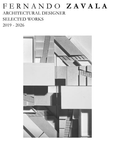
FERNANDO ZAVALA ARCHITECTURAL DESIGNER SELECTED WORKS 2019 - 2026
FERNAND
Architectural Designer & New York, NY | Lima, Peru | fz
OBJECTIVE
The epitome of my design work has developed through thinking of architecture as a service, as a solution, or as an agent of change, through interdisciplinary, sustainable and human-centered design, at the intersection of nature, human biology, and the built environment in order to foster human health and wellbeing for the betterment of the human condition. Moreover, really looking at how certain factors in the built environment can have an effect on one’s physical and mental state. Within my experience in academia, I have become enriched by new landscape urbanistic strategies that have berthed a wave of design thinking that prioritizes resilience and interdisciplinary, dynamic, process-based architecture within the public & private realm in order to garner community engagement and harmonious co-existence. I believe my multiculural upbringing has served as a foundation for my designs, integrating lifelong economic, political and socio-cultural perspectives. After five years of real world professional experience following a four-year architectural bachelors degree, I have equipped numerous professional and academic experiences of different sizes, scopes and specializations (retail, commercial, residential, civic design, graphic design, visualization, 3D modeling, drafting, construction, research, etc.) that has helped solidify a certain proficiency along all design phases, manifesting a very diversified and fluid design ethos. My goal is to further expand my knowledge on these growing strategies and bound-less generative architectural systems, technologies and methods that are at the cutting edge of the architectural discipline (primarily focusing on human health, equity, and sustainability) to hopefully discover a way to harmoniously and realistically integrate them into the built environment.
EDUCATION UCLA School of Architecture and Urban Design
Los Angeles , CA
Graduate M.Arch I Professional Degree | September 2024 - May 2027
- Honor Student, Spring 2025 Best Work Nominee for Core Studio, Work featured on UCLA AUD website/socials, Introductory Studio AI Workshop Team Lead, AIAS Design Competition Member
- GPA: 3.95
University of Virginia, School of Architecture
Charlottesville, VA
- Undergraduate Bachelors of Science in Architecture | August 2017- May 2021 - Minor in Urban Planning and Development - AIAS member, National Organization of Minority Architecture Students (NOMAS) member, UVA Architecture Alumni Mentorship Program member, IFC Diversity and Outreach Committee Graphic Designer, MSS Latinx Leadership Institute Presenter - GPA: 3.5
RECOGNITIONS LA Design Festival “Design Futurism” Exhibition Proposal Selection/Acceptance | June 2025
Los Angeles, CA
- Member of the select group of graduate students pulled from top SoCal architecture programs (including UCLA, USC, Berkeley, etc.) to present exemplary academic studoi work to be experienced in an immersive 3D VR experience through ‘Future Tense’ design team at this annual, highly touted LA design conference
Simons Foundation Rooftop Competition
New York, NY
Winning Candidate | January 2022- September 2024 - Our TPG retail studio team received the most votes from Simons Foundation ownership on our design proposal, amongst six other competing top NYC based architecture firms, for a new event space on the roof of Simons Foundation building (160 5th avenue). -Primarily developed and presented 3D model and detailed proposal drawings, plans and sections, as well as site and zoninf analysis diagrams & documents and rendered views
UVA School of Arch: Intro to Design Thinking Course
Charlottesville, VA
Student Instructor | January 2021- May 2021 - Asked to TA for the School of Architecture’s well known ‘Intro to Design Thinking’ course and tasked with leading a team of twelve students into the world of design through numerous illustrator and photoshop exercises and design explorations; offering several design tutorials, reflections and constructive sessions, practicing pertinent leadership and communicative abilities, learning organizational, logistical, as well as pedagogical/didactic skills
O ZAVALA
& UCLA Masters Student zavala@g.ucla.edu | 434-906-7502
WORK EXPERIENCE
UCLA Hammer Musuem
Los Angeles, CA
Gallery Ambassador |May 2025 - Present - Maintaining daily operational and logistical duties of sveral exhibitions and galleries within the museum, organizing and scheduling educational tours, maintaining gallery standards, managing museum sponsered events, museum security, team rotations, and ensuring the safety of artworks and guests
TPG Architecture
New York, NY
Project Professional & Intermediate Designer | December 2021 - September 2024 -Developed and documented several retail, commercial, multi-purpose and civic projects across a spectrum of scales, phases and scopes, including rigorous site & zoning analysis, code compliance, project coordination/scheduling, material sampling and design development of certain projects such as the ground-up flagship store for ‘El Palacio De Hierro’ high-end department store in Mexico.
Sargenti Architects
Paramus, NJ
Junior Designer & Architectural Drafter | September 2021 - December 2021 - Developed shop drawings, reports and submittals for several upcoming renovated Target test-fits, stores and locations, and coordinating architectural, mechanical, electrical and plumbing drawings - Annotating, detailing and dimensioning sheets and sets for these new retail spaces in Revit and CAD primarily
Parsippany, NJ
PAD Architects
Junior Designer | June 2021 - October 2021 - Chiefly in charge of assisting in development of various residential and commercial projects; responsibilities ranged from site surveys, schematic design production and renderings/visualizations to construction documentation, permit drawings, and redlinings predominantly in CAD, Revit, Rhino, Lumion and Sketchup & created, curated and finalized client presentations in Indesign and Illustrator
University of Virginia Architecture Department
Charlottesville, VA
Research Assistant| January 2021- August 2021 - Member of mostly graduate WBYA research team focused on producing and organizing literature reviews & panels on the topic of fair human labor rights & conditions, as well as designing a school campaign exhibition focusing on raising issues of the disconnect between architects and the labor force/construction industry, thus becoming very familiar with real world construction methods
KUBE Architects
Washington, DC
Architectural Extern | January 2021 - Partook in UVA’s shadowing program, assisting in the firm’s daily duties, sitting in on meetings with contractors, engineers, and learning critical realistic operational skills, from building a network to managing the day-to-day of an architecture firm
Pfizer Inc
New York, NY
Digital Team Graphic Design Specialist | June 2019 - August 2020 -Primary researcher behind market investigations regarding digital vaccination decisions in Argentina for the adult pneumococcal vaccine, utilizing SEO tools, online digital analytics and visualizing findings to form coherent, graphically rich presentations. - Head of new-hire graphic team responible for creating an action plan in order to implement iterative, collaborative design thinking aspects into the daily operations of this corporate workflow environment
Elgin Cleckley
REFERENCES
Professor, Supervisor & Director
Jennifer Roe
Professor, Advisor
Eladio Victoria
Associate, Senior Designer
elc2n@virginia.edu jjr4b@virginia.edu
evictoria@tpgarchitecture.com
INTERESTS
Landscape /Ecology Urban Planning / Development Sustainability Biophilic /Resilient /Empathic Design Graphic Design Computer Fabrication / Visualization Automated Construction
TECHNICAL SKILLS
ArcGIS Pro AutoCad Acrobat Bluebeam Google Earth Pro Excel Rhinoceros Revit / BIM360 SketchUp Pro Photoshop Illustrator InDesign Adobe Premiere Grasshopper V-Ray Lumion Enscape Midjourney / Dall-E Microsoft Office
6 years 8 years 8 years 4 years 4 years 7 years 7 years 6 years 7 years 8 years 8 years 8 years 4 years 6 years 6 years 5 years 5 years 2 years 8 years
PROFESSIONAL SKILLS
Design thinking Arch. Visualization 3D Modeling Graphic Design Interior Design Diagramming/Sketching Project Coordination Arch. Drafting Construction Docs Site/Zoning/Code Analysis Presenting/Public Speaking Photography Lazer cutting 3D printing Rockite Casting Woodshop modeling English Spanish French Portuguese
8 years 8 years 8 years 7 years 6 years 6 years 4 years 4 years 4 years 3 years 5 years 6 years 6 years 5 years 5 years 5 years Native Native 6 years 5 years
CONT UCLA PROJECTS 1. ‘HYDROASIS’ | 6 AUD 413: Building With Landscape Studio | Resilient Waterways as Publicscape Fall 2025 | Los Angeles, CA Narineh Mirzaeian
2. ‘CONVERGENCE’ | 12 AUD 401: Housing LA Studio | Reframing the American Dream Spring 2025 | Los Angeles, CA Yara Feghali
3. ‘LIVING LATTICE’ | 18 AUD 412: Inside Outside Architecture | Structure and Order Winter 2025 | Los Angeles, CA Heather Roberge
4. ‘STITCHING THE SHORE’ | 24 AUD 411: Introductory Design Studio | Proto-Architecture Fall 2024 | Los Angeles, CA Max Kuo
5. ‘SPATIAL MEDIATIONS: 3D LIGHT CAST’ | 28 AUD 221: Architectural Mediation | Space Volume Module Fall 2024 | Los Angeles, CA Miroslava Brooks
TENTS PROFESSIONAL PROJECTS 6. ‘LA ISLA’ URBAN VILLAGE | 32 TPG Design Studio | Rejuvinating Community Shopping Complex June 2022 - June 2023 | Cancun, MX Alec Zaballero
7. 160 5TH AVE ROOFTOP COMP. | 40
exported 10/15/2023 5:13:46 PM
TPG Design Studio | An Event Space Dedicated to Science December 2021 - January 2024 | New York, NY Ray Gavargis
8. PALACIO DEPT. STORE FACADE | 48 TPG Design Studio | Revitalizing Mall Entry May 2023 - August 2024 | Monterrey, MX Vlad Zadneprianksi FLOOR NAME DEPARTMENT NAME FURNITURE PLAN, ELEVATIONS & DETAILS
AS NOTED XXX
PB-PF-01 X-Mall-Entradas_South - COPY FZ.dwg
OTHER PROJECTS 9. ‘NEXUS’ | 54 Research Studio II: Arch 3020 | Rethinking Residential Life at UVA January 2020- May 2020 | Charlottesville, VA Professor: Devin Dobrowolski
10. ‘EVOLUTION’ | 60 Housing Studio II: Arch 2020 | Radical Domesticities January 2019 - May 2019 | Charlottesville, VA Professor: Gonzalo Alonso
11. ‘CAST-LESS:’ GENERATIVE ORTHOSIS | 66 Robotic Behavioural Fabrication: Arch 5500 | 3D Immobilization Systems August 2020- December 2020 | Charlottesville, VA Professor: Ehsan Baharlou
HYDROASIS In light of the multifaceted challenges posed by the environment and the imperatives of sustainability, this studio looks to question architecture’s agency in recalibrating infrastructural paradigms to ensure equitable natural resousrce access. Thus, this studio focuses on mapping, analyzing, and generating ordering systems of natural and constructed landscapes operating across diverse ecologies within the new ‘Headworks’ Reservoire site in Los Angeles situated to the north of Griffith Park. Part 1 of this project revolved around the mapping of hidden hydrologic flows in order to explore the gradient between the fluid and the structured, the natural and the man-made, within the context of water reservoirs and water treatments around the LA area. In effect, we chose three precedent reservoir sites on the outskirts of the LA metropolitan area in order to uncover the spectrum of man made intervention within natural bodies of water, and how they affect the surrounding urbanity, hydro-infrastructure, and biology/wildlife. Upon our investigations, we discovered a direct relationship between the more natural fluid dynamics of the reservoir’s surrounding water ways, and the ecological and environmental richness of those areas. Overall, the areas where natural water flows weren’t sped up or tampered with for man made purposes such as storage, damming actions, flood control, etc., ‘riparian’ zones became bountiful and thrived, leading to more concentrated and maximized areas of fertile soil, vegetation growth, wildlife habitats, etc, berthing a more organic, highly optimized ecological life to these areas alongside the riverbed. This project team consisted of myself and two fellow UCLAclassmates; Harry Huh and Alanis Baez; all the drawings selected here have been majorly and primarily worked on and developed by me.
MAPPING ANALYSIS OF LOS ANGELES MAN-MADE VS NATURAL RESERVOIRS
Riparian zones refer to these crucial buffer or transition zones between aquatic and terrestrial ecosystems along the river where specific moist and wetland conditions support high biodiversity, rich ecologies, water filtration and stabilization, and flood control. Thus, for Part 2 of this studio, where we are meant to spatialize our mapping discoveries and apply them to our specific space, we wanted to focus on the potential of these zones along our site, maximizing and containing these areas in order to cultivate resilient, resrouce-efficient and public-centric imaginaries that meaningfully engage the urban fabric, activating and connecting with the new reservoire initiative surrounding the site, essentially creating a water complex that acts as a demo landscape, reshaping, collecting and channeling water in support of an idealized, restored hydrology in LA.
SILVERLAKE RESERVOIR
PRAIDO RESERVOIR
ELSINORE RESERVOIR
‘UNROOFED’ GF PLAN (SCALE: 1’ = 1/400” )
SECTION A (1’ = 1/50”)
SECTION B (1’ = 1/50”)
SECTION ‘A’ (SCALE: 1’ = 1/100”) )
SECTION C (1’ = 1/50”)
SECTION ‘B’ (SCALE: 1’ = 1/100”) )
SECTION ‘C’ (SCALE: 1’ = 1/100”) )
SITE PLAN (SCALE: 1’ = 1/400” )
Our proposal reimagines existing conditions by reshaping the river into a more natural, erosion-based system. We introduce a weaving meandering flow that allows water to slow, disperse, and actively reshape the terrain through erosion and deposition. This restores the dynamic riparian zones that cannot exist within the current containment model effectively bringing the river back to it’s desired state. This also creates a site-wide gradient of interactions. At the urban edge, architecture is more defined guiding circulation, organizing program, and providing shade. As we move toward the river, that architecture becomes porous, lifted, and eventually dissolves as the riparian processes take over. A key mediator of this gradient is our roof system. The roof frames the urban boundary but also becomes ecological infrastructure. Its large modular surface acts simultaneously as: 1) a water-collecting system, channeling rainfall into filtration zones and supporting the restored hydrology, and 2) a solar-generating field, with panels integrated into select grid modules to power site demand
FIGURE GROUNDS
ROOF
MASSINGS
GROUNDSCAPE
MAIN PATH
RIPARIANS
ENLARGED GF PLAN (SCALE: 1’ = 1/50”)
SITE RENDER
The riparian zones act as magnets, pulling the architecture around ecological corridors. This creates a more porous, responsive ground condition where built form and landscape overlap and the massings act as mediators. At the urban edge, the system is more formal and enclosed. But, moving toward the river, the modules filled with program responding to the water complex (classrooms, exhiibitionhalls, research labs, etc.) get carved, or disappear entirely. The architecture transitions from enclosure to exposure, allowing vegetation, water, and erosion to actively shape the edges over time. The roof ties the whole strategy together—collecting water, generating solar energy, and acting as a continuous canopy that guides visitors through the gradient from the structured city edge into the restored riparian environment. In conclusion, this project is not a fixed object but a framework — one that supports ecological restoration, human use, and environmental performance simultaneously. By allowing the river to return to a natural erosion-based system, and by embedding water collection, solar energy, and habitat surfaces into the roof, we propose a model for architecture that works with natural forces instead of against them.
AMPITHEATRE RENDER
RIPARIAN RENDER
SECTION OBLIQUE FACING SOUTH
CONVERGENCE
My double lot residential housing proposal aims at addressing a more diverse and community driven housing landscape for the future of LA that breaks down the dominance of the single-family home and redefines the traditional “California dream.” The focus of my project was about manipulating the ‘duplex’ housing typology in order to maximize social interaction among my residents through thinking of the circulation as the spaces of congregation and collection for the community. It was about taking the configuration of the ‘Y’ shape, which came from preliminary explorations, which sort of breaks up and twists as you go upward and almost kisses at the top, in order to create this rising symmetrical landscape of circulation that in itself becomes the communal spaces for the residents. Thus, at every level, some of the legs of the ‘Y’ become these offset exterior terraces hugging and nesting the main stairs, while the leftover, ‘in between,’ Y spaces foster a spectrum of alternating exterior terraces/gardens. The formal logic across the site is divided and dictated by an axis of symmetry, as I was also really interested in the idea of centrality, especially with the perceived lack of centrality in LA, thus creating an elevated central plaza. . In terms of program, the sunken ground floor offers a large shared amenity space with pool, service areas, gym and laundry facilities, framing half level views between residents and community space, and utilizing space under circulation too. For the second and third stories it becomes about expressing it on the fenestration and apertures, in a way that it becomes a gradient from orthogonal apertures to angled corner windows, maximizing views and social interaction. I thought it would be interesting to express Y in elevation in separate ways, where the diagonal is informing the angle of the walls, creating a more porous and transparent GF/ basement. Overall, it becomes about utilizing the ‘Y’ diagonal form to optimize different levels of social interaction in a way that the circulation spaces become the communal spaces, maximizing them and hving them convereged in one.
FINAL CHUNK MODEL PHOTO
GF & SUBFLOOR PLAN
2ND FLOOR PLAN
SCALE: 1’ = 1/32”
SCALE: 1’ = 1/32”
3RD FLOOR PLAN
‘A’
SCALE: 1’ = 1/32”
PHYSICAL CHUNK MODEL & ‘A’ SECTION COLLAGE
AXO DIAGRAM 1: COURTYARD CIRCULATORY LANDSCAPE
PERSPECTIVE COLLAGE
AXO DIAGRAM 2: GF DOUBLE HEIGHT 900 SQFT ADU UNIT
AXO DIAGRAM 3: SECOND FLOOR 600 SQFT STUDIO UNIT In axon, we can see these two formal gestures of the rising spiraling pockets of communal spaces, and the more private, secluded leftover ‘Y’ terrace spaces working simultaneously, leaving it unexploded on one side, and then exploded on the right, where we see the series of platforms hugging the stairs that circulate clockwise vertically, and where the units offset and mirror the circulatory procession. There was an interesting challenge present with the symmetry and the issue of uneven unit count requirement, which was solved through taking the typology of the duplex and tucking certain units underneath the stairs (creating double height spaces) and breaking up the legs of the ‘Y’ morphologies into different units, one two story and one studio.
SOUTH ELEVATION (SCALE: 1’ = 1/32”)
LONG SECTION FACING NORTH (SCALE: 1’ = 1/32”)
LIVING LATTICE This studio revolved around the speculative transformation of an existing structural system in the built environment to breed interesting architectural opportunities within the context of an urban arboretum proposal. My precedent was the Hall of Nations by Raj Rewal (structural diagrams and details below). From there, a catalog of structural space frame systems translations were generated using the pyramidal space unit as the typological module. This then informed the fragment model photographed here, aimed to convey an array of a proto architectural structural system modifying and enhancing the extracted structural system from the precedent. Furthermore, certain structural and spatial gestures were chosen and capitalized upon to situate my final proposal within our LA site and under the guidelines of our programmatic prompt of the arboretum. The final project centered around creaitng different levels of pruned pyramidal space frames through an array of trussed lattices in order to foster a variety of spatial experiences/densities, primarily through the dynamic inhabitability of the structural column.
FINAL FRAGMENT MODEL PHOTO
FINAL FRAGMENT MODEL PHOTO
PRECEDENT STUDY DIAGRAMS Part 1 of this studio consisted of an exercise in assigning and applying a specific structural phenomenon from Heino Engel’s “Tragsysteme,” to our chosen precedent building. For the Hall of Nations, by Raj Rewel, we identified the implementation of a vector-active structural system, one which consists of various triangular members operating in multiple axes.
We wanted to express the evolution from single structural module, the triangle, to the pyramidal member, which then gets mirrored, arrayed and multiplied in order to generate a space truss that begins to span as a space frame in order to form the roof and wall conditions of the exhibition hall.
PART 1 STRUCTURAL CATALOG AND PROTO ARCHITECTURAL ITERATIONS From there, we started iterating on the main existing trinagular unit module, coming up wth a plethora of different pyramidal space frame operations and configurations so as to explore and present a number of different architectural possibilities. This was then translated and organized into a catalog of spatial operations for the pyramidal unit module, which can then be iterated on at a larger elevation scale (left) in order to foster a gradient of densities, volumetrics, and formal outcomes of the building. The physcial model was then built as a representational tool to convey the amalgamation of different spatial operations, from vertical space truss (column) , to fractal frame (floor), to typical space frame (roof). Thus, different architectural elements could then be fitted, spaced, densified, and oriented in order to offer an optimal variety of natural light magnitudes and types, providing maximal architectural performance for the arboretum as a whole.
FINAL FRAGMENT MODEL PHOTO
The urban arboretum project assignment (Part 2) really revolves around capitalizing on the architectural capabilities of the previous structural exploration of the pyramidal space frame. Essentially, an extended array of carved out, emptied and pruned structural space frames, or trussed lattices, berths an architectural gradient of space and scale; maximizing and taking advantage of different densities of spatial conditions. The natural density of the space frame was harnessed for climate and atmospheric considerations, repurposed to act as a sun blocker or light modulator, while the carved out trussed lattices made way for more spatial possibilities, which were then vertically aggregated to berth flying, multilevel greenhouses that simultaneously act as skylight atriums. In this way, the subtle typological structural spectrum was utilized in order to recontextualize the project into a space that offers a variety of existing dualities, a space that optimizes and maximizing different magnitudes and types of daylight throughout the day for the plantlife of the arboretum, a space that fosters a visual interplay between plant and person until they finally physically meet at the larger scale arboretum areas, and a space that acts as an urban solution to engage the adjacent park and surrounding community.
FINAL (FULL SITE) PHYSICAL MODEL COLLAGE
DIAGRAM: MAIN SPATIO-STRUCTURAL OPERATION From space frame to pruned trussed lattice - Vertical greenhouses become inhabitable structural columns
EXPLODED AXO 1: TWO STORY GREENHOUSE
2ND LEVEL STRUCTURAL PLAN (SCALE: 1’ = 1/50”)
PERSPECTIVE SECTION FACING NORTH
EXPLODED AXO 2: THREE STORY GREENHOUSE
STITCHING THE SHORE This project really revolved around considering the building as the connective tissue between the two different typologies of the waterfront/urban and the coast/beach. In essence, a landscape of connective pathways was born, within which the curvilinear language explored during previous projects maximizes the circulatory experience, and the circulatory spaces really become the collective/static spaces of visual connectivity and activity. Certain formal narratives grew from this overarching concept; mainly the continuity of the curve to maximize spatial experiences, including the atriums becoming embedded into the infilled stepped landscape (almost as if one with the Earth) as well as a reverse figure ground implementation from the roof ’s clear extruded geometries (that serve as clerestory windows or skylights) as one goes deeper underground. Ultimately, contrasting the open curvilinear roofscape, the bottommost, ground floor plan offers a condensed, tight circulatory experience straight from the beach access, which then opens up and widens in scale once the large, deep embedded atriums are ‘discovered’ upon. Programmatically, this allows for a variety of flexible spaces where the line between interior and exterior are blurred, as well as the optimization of visual connectivity between programs, without direct, physical interaction or disruption.
PAPER RELIEF MODEL + SKETCHES COLLAGE
GROUND FLOOR PLAN (SCALE: 1’ = 1/50”)
2ND FLOOR PLAN
FERNANDO ZAVALA
0 1’
3’
5’
10’
20’
EVOLUTION OF HYBRID DRAWING TO PHYSICAL MODEL
Site: COAST
FERNANDO ZAVALA
FINAL MODEL PROMENADE PHOTOS
TRANSVERSE PERSPECTIVE SECTION FACING EAST
SPATIAL ME 3D LIGH
This final module’s main goal was to experiment with differen negative volumetric studies. Firstly, the 3D printed mass was c enclosure, essentially creating a shell cast with which an 3D pr color filament is revealed which create interesting and ambigu and shadow studies can be explored. It was also an effort to e poetically capitalizing on the imperfections and mistakes in the instead of letting it stifle the creativity and craftsmenship.
EDIATIONS: T CASTS
nt spatial modeling techniques through a series of positive and cast in plaster, and finally cast as negative space wihtin a cubic rinted architectural and spatial interior volume made of multiuous moments, details and openings within which certain light experience the real life logistical considerations of casting, and e modeling process in order to help drive the artistic narrative,
FINAL PLASTER OBJECT + 3D PRINTED CAST
PRUNED PLASTER ENCLOSURE WITH NEGATIVELY SPACED PLASTER OBJECT
PROGRESSION OF MODEL MODULES
LIGHTING STUDIES: CUBE APERATURE 1
LIGHTING STUDIES: CUBE APERATURE 2
LIGHTING STUDIES: CUBE APERATURE 3
LA ISLA SHOPPING VILLAGE
The core of this project revolves around the restoration and rejuvination of an existing urban shopping complex located on the hotel strip of Cancun, Mexico. This approximately 300,000 square foot, multi-scale undertaking consists of three different project scopes, exterior facade renovation, front green slow street/promenade renewal, and the ground-up development of the interior shopping plaza & interior courtyard. As a whole, we aimed to fully transform the shopping experience through a hierarchy of dynamic, high-end contemporary elements blending together to not only pay homage to the local Mexican climate tropical boime, but to berth an urban landscape in and of itself, an ‘upscale jungle oasis,’ if you will. The project team consisted of select members of the TPG retail design team, including managing executive Alec Zaballero, project manager Eladio Victoria, and senior architect Ana Misenas. My role consisted of contributing certain design opinions, as well as producing master 3D model, renderings, visualizations, CAD drawings and details. Every depiction shown henceforth, with the exception of existing base plans or column grids, is work of my own, that I have chiefly constructed, developed, and submitted.
Existing plan
n provided by client, projection and diagrammatic visualization developed by myself
EXISTING URBAN SCALE PROJECTED PLAN INTERIOR PLAZA FACADE GREEN SLOW STREET
PROPOSED URBAN SCALE DESIGN RESTORATION AERIAL VIEW
FACADE DESIGN The design strategy behind the facade restoration was centered around the development of a biomimetric language evoking the surrounding natural landscape while simultaniously guiding the user through a mix of angular and curvalinear elements, driven by a series of front-lit rhythmic, nested, polished metal verticals backed by perforated bronze panels. Effectively, this typology becomes the unified juxtaposition that not only draws a statement towards the facade of the urban complex, but acts as the connective tissue between the interior and exterior languages.
PROPOSED FACADE RENDER | FRONT ENTRANCE NIGHT VIEW
FACADE EAST ELEVATION | R
PROPOSED FACADE RENDER | PARKING LOT DAY VIEW
RENDER/DRAWING COLLAGE
EX. GREEN SPACE/CIRCULATORY CONDITIONS
PROPOSED GREEN SLOW-STREET INTEGRATION
- New four meter sidewalk - Extended pedestrian walkway - New three-lane transit streetway - Enriched landscaping through planters, permeable pavers, & vegetation - New three meter wide cobblestone roadway - New green seating modules
SCALE: 1’ = 1/200”
SCALE: 1’ = 1/150”
GREEN SLOW-STREET DESIGN For the restoration of the green slow street/promenade, we wnated to re-infornce the human scale, by adding certain pedestrian elements that eased the gradient or transition from automotive traffic to human traffic. This consisted of thoughtfully composed and placed planter modules, seating areas, green areas, and the integration of a slow cobblestone roadway that bleed into these green areas through the use of permeable pavers and material con siderations. In a sense, these gestures create a visual threshold and balance between the on-foot vs transit experience (pickup-area, parking and valet).
PROPOSED GREEN SLOW-STREET RENDER | AERIAL VIEW
SLOW-STREET RENDER | STREET VIEW
SLOW-STREET RENDER | PICK-UP AREA VIEW
INTERIOR PLAZA DESIGN The genesis of the interior plaza design starts with building upon the exterior facade typology at a smaller, private scale, by establishing the more angular, aggressive visual forms through the harmonious implementation of neutral piers, a unified storefront fascia vocabulary, an island courtyard/lounge with a decorative stair, a moat, new orthogonal rooftop canopies with wooden slats/louvers, and more intentional, floor finishes (terrazo and herringbone tile pattern composition), as well as local flora and fauna.
PROPOSED INTERIOR SHOPPING COMPLEX FIRST FLOOR FINISH PLAN (SCALE: 1’ = 1/100”)
exported 7/21/2022 5:44:33 PM
exported 7/21/2022 5:44:34 PM
PROPOSED INTERIOR SHOPPING PLAZA RENDER | ENTRANCE VIEW N9
N-F
6
BULKHEAD AND NEW CONCRETE STUCCO FINISH FACADE
9.0 4
4.2
(5) UNITS OF CANOPY MODULE [B]; B.O. CANOPY 12.67m A.F.F.
B
4.2
B
.6
12
.2
7.2
21
7.8 2
12
12.28 m A.F.F. ROOF_LEVEL -BASELINE
NEW FASCIA IN CONCRETE FINISH (5) UNITS OF CANOPY MODULE [B]; PLASTER B.O. CANOPY 11.60m A.F.F. C-1
(3) UNITS OF CANOPY MODULE [A]; B.O. CANOPY 13.50m A.F.F.
NEW BEAMS AT ANCHORED TO NEW STRUCTURE, VERIFY STRUCTURE WITH STRUCTURAL ENG. F-1
B S-1
0.7
FLOOR -TRAVERTINE ST-1
BY TENANT/VENDOR 4.10
21.2
6.4 B
7.91
4.2
4.2
(5) UNITS OF CANOPY MODULE [B]; B.O. CANOPY 10.70m A.F.F.
B
B
STAIR BEAMSN AND ALL STEPS IN CONCRETE FINISH C-1
ROOF CANOPY PLAN (SCALE: 1’ = 1/75”)
1
ROOF PLAN ABOVE PLAZA
N9
4.2
GENERAL SECTION 1 AT PLAZA
REFLECTING POOL AROUND PLAZA IN CONCRETE FINISH
REFLECTING POOL AROUND PLAZA IN CONCRETE FINISH
GLASS RAILINGS WITH LED LIGHTING AT HANDRAIL AS PER LIGHTING SPECIFICATIONS
METAL NEUTRAL LINTEL
0.0 m A.F.F. PB_LEVEL 3-BASELINE
REFLECTING POOL AROUND PLAZA IN CONCRETE FINISH
GENERAL SECTION A @ PLAZA STAIRS (SCALE: 1’ = 1/50”) SCALE 1:150
METAL TRELLIS WITH FRAMED GLAZING ON TOP, ANCHORED WITH TENSION RODS AND BRACE BEAMS, VERIFY STRUCTURE WITH STRUCTURAL ENG. AND WATER DISCHARGE WITH MEP AS REQUIRED (TYP).
6
BY TENANT/VENDOR 4.00
4.2
0.15
4.2
0.30
4.2
(5) UNITS OF CANOPY MODULE [B]; B.O. CANOPY 12.30m A.F.F.
3.43
1.7 7.91
1.47
4.2
0.15
4.2
M-1
4.2
5.40
6.4 0.17
1.28
4.2
(5) UNITS OF CANOPY MODULE [B] W/ CANOPY FRAME; SEE DT'L [7/A205]; TYP.; B.O. CANOPY 11.20m A.F.F.
F-1
BY TENANT/VENDOR 4.00 5.90
6.4
9
3.37
WOOD FINISH NEUTRAL HEADER (TYP)
1
1.0 3.1
F-1 M-1
5.44 m A.F.F. PN_LEVEL -BASELINE
4
8.4
21.2
PLANTER BED WITH DRAINAGE AS REQ, AND DRIP IRRIGATION
14.34
8
4.7
C
21.2
S-1
4.85
F-1 M-1
1.00
.8
12
BY TENANT/VENDOR 4.10
6.2 .8 18
A
2
METAL TRELLIS WITH FRAMED GLAZING ON TOP, ANCHORED WITH TENSION RODS AND BRACE BEAMS, VERIFY STRUCTURE WITH STRUCTURAL ENG. AND WATER DISCHARGE WITH MEP AS REQUIRED (TYP). F-1
NEW BEAMS AT ANCHORED TO NEW STRUCTURE, VERIFY STRUCTURE WITH STRUCTURAL ENG. F-1
.8
4.2
15.88 m A.F.F. TOP OF BULKHEAD
METAL TRELLIS WITH FRAMED GLAZING ON TOP, ANCHORED WITH TENSION RODS AND BRACE BEAMS, VERIFY STRUCTURE WITH STRUCTURAL ENG. AND WATER DISCHARGE WITH MEP AS REQUIRED (TYP). F-1
0.50
A
COLUMNS IN METAL VERIFY WITH STRUCTURAL ENG. AND WATER DISCHARGE WITH MEP AS REQUIRED(TYP). M-3 F-1
B
9
1.5
6.0
4.2
COLUMNS IN METAL VERIFY WITH STRUCTURAL ENG. AND WATER DISCHARGE WITH MEP COLUMNS IN METAL VERIFY AS REQUIRED(TYP). WITH STRUCTURAL ENG. AND M-3 WITHF-1 WATER DISCHARGE MEP AS REQUIRED(TYP).
exported 7/21/2022 5:24:47 PM exported 7/21/2022 5:24:47 PM
ENLARGED PROPOSED INTERIOR SHOPPING COMPLEX SECOND FLOOR FINISH PLAN (SCALE: 1’ = 1/50”)
N9
EXISTING OPENING TO REMAIN
N-F
6
4.2
B
9.0
0.78 2.1
6.4
4.2 12.6
1.28
4.2 2.1
3.37 6.4
4.2
9
3.1
NEW BEAMS ANCHORED TO NEW DUNNAGE & CANOPY MODULES
1.7 7.91
4.2
4.2
4.2
4.2 MT'L7.91 TIE-ROD W/ TURN BUCKLE; FASTEN TO MT'L BEAM BTWN CANOPY MODULES & TO VERTICAL MEMBERS OF MT'L DUNNAGE
4.2
METAL NEUTRAL LINTEL
(5) UNITS OF CANOPY MODULE [B] W/ CANOPY FRAME; SEE DT'L [7/A205]; TYP.; B.O. CANOPY 11.20m A.F.F.
(5) UNITS OF CANOPY MODULE [B]; B.O. CANOPY 12.30m A.F.F.
4.2
4.2
B
N9
4.2
B
0.0 m A.F.F. PB_LEVEL 3-BASELINE
1
(5) UNITS OF CANOPY MODULE CANOPY FRAME; SEE DT'L [7/A TYP.; B.O. CANOPY 11.20m A.F
(5) UNITS OF CANOPY MODULE [B]; B.O. CANOPY 10.70m A.F.F.
B
B
ROOF PLAN ABOVE PLAZITA
2
SCALE 1:150
ROOF PLAN ABOVE PLAZA
REFLECTING POOL AROUND PLAZA IN CONCRETE FINISH
GLASS RAILINGS WITH LED LIGHTING AT HANDRAIL AS PER LIGHTING SPECIFICATIONS
PROPOSED INTERIOR SHOPPING PLAZA RENDER | 2ND FLOOR VIEW 1 2 ROOF PLAN ABOVE PLAZITA
ROOF PLAN ABOVE PLAZA
SCALE 1:150
SCALE 1:150
ECTION 1 AT PLAZA
SCALE 1:75
0.05
CL
CL 0.05
3.9 (8) EQ. SPACES
0.1
CL 0.05
3.9 (8) EQ. SPACES
4
F-1
M-3
6 A-205
4 4
F-1
0.05 C L
0.05
VARIES
CL 0.05
3.9 (8) EQ. SPACES
0.2
0.1
F-1
0.2
4
CANOPY FRAME 0.2m X 0.4m MT'L TUBE FRAME; MITER @ CORNERS. OVERALL DIMS VARY, SEE DWG 2/A205
0.2
0.1
COLUMNS IN METAL VERIFY WITH STRUCTURAL ENG. AND WATER DISCHARGE WITH MEP COLUMNS IN METAL VERIFY AS REQUIRED(TYP). WITH STRUCTURAL ENG. AND M-3 WITHF-1 WATER DISCHARGE MEP AS REQUIRED(TYP).
17.00
CL
0.30m Ø PIPE F-1
0.60
F-1
FASTEN MT'L PLATE TO T.O. CANOPY FRAME
IN CONSIDERATION OF RECEIVING DRAWINGS FROM TPG ARCHITECTURE LLP IN FASTEN CLEVIS' TO PLATES PROVIDED AUTOCAD FORM, THE RECIPIENT AGREES, TO THE FULLEST EXTENT PERMITTED AT CANOPY BEAM AND BEAM AS LLP FROM BY LAW, TO HOLD HARMLESS AND INDEMNIFY TPGRING ARCHITECTURE AND AGAINST ALL CLAIMS, LOSSES, DAMAGES, AND COSTS, REQ'D LIABILITIES, TO SUPPORT CANOPY INCLUDING BUT NOT LIMITED TO ATTORNEY'S FEES, ARISING OUT OF , OR IN ANY WAY CONNECTED WITH THE USE, RE-USE, MIS-USE, MODIFICATION, OR BUCKLE MISINTERPRETATION OFTURN THE MACHINE-READABLE INFORMATION PROVIDED BY TPG ARCHITECTURE LLPPROVIDE UNDER THIS AGREEMENT. MT'L TURN BUCKLE AS REQ'D
14,12
11.60
11.40
13.30
0.2
CANOPY MODULE 'A'
0.2
0.49
(2) .04m X .07m X 0.10m LONG CHANNEL; TO BE DESIGNED BY STRUCTURAL ENGINEER
OPEN
RUN CONDUITS ABOVE MODULE FRAME & STRINGERS; TYP.
0.49
0.05
CANOPY FRAME
PLANT BED FOR PALMS AND LANDSCAPE
BACK OF BENCH AND CURB IN CONCRETE PROVIDE RE-CIRCULATING WATER DRIP FOUNTAIN IN BACK OF COFFEE STAND, PROVIDE REQ. PLUMBING AS REQ.
STRINGERS 0.10m X 0.30m X 5.8m LONG MT'L TUBES; FASTEN TO FRAME @ BOTH ENDS AS REQ'D; TYP.
SCALE 1:50
AS REQ'D TO SUPPORT CANOPY
5.44
BLVD, KUKULCAN KM 12.5 ZONA HOTELERA,MT'L CANCUN PLATE @ PARAPET
ANCHOR MT'L PLATE TO MT'L TUBE; PROVIDE OPENING AS REQ'D TO
CANOPY MODULE 'B'
RING BEAMS AT PARAPET
MODULE FRAME 4m x 8m FRAME OF 0.10m X 0.30m MT'L TUBES; MITER AT CORNERS
PLANT BED FOR PALMS AND LANDSCAPE COFFEE BAR STATION FINISHES AND FURNITURE BY OPERATOR, PROVIDE PLUMBING, ELECTRICAL AS REQ.
4
PARAPET
0.0 m A.F.F. PB_LEVEL 3 - BASELINE
F-1 SCALE 1:50
5
MT'L STUB ANCHOR MT'L TUBE TO UPPER
STRINGERS RING BEAM AT PARAPET 0.10m X 0.30m X 7.8m LONG MT'L TUBES; FASTEN TO FRAME @ BOTH ENDS AS REQ'D; TYP. F-1
SCALE 1:75
EV
T.O. FINISHED FLOOR
A-802
CANOPY MODULE C
CANOPY ASSEMBLY
1:150
SECTIONS_PLAZA.dwg
SCALE 1:50
6
ANCHOR 0.20m Ø S.S. PIPE TO MT'L PLATE
MODULE FRAME 4m x 6m FRAME OF 0.10m X 0.30m MT'L TUBES; MITER AT CORNERS F-1
STRINGERS FASTEN MT'L PLATE TO T.O. FINISHED FLOOR 0.10m X 0.30m X 5.8m LONG MT'L TUBES; FASTEN TO FRAME @ BOTH ENDS AS REQ'D; TYP. F-1
CANOPY DETAIL D
CANOPY ASSEMBLY DETAIL
TPG
31 PE 132 W 212.76
IN CON AUTOC BY LAW AND A INCLUD ANY W MISINT TPG AR
FU LA
BLV HO
R C
0.30m Ø PIPE F-1
BUILDING SECTION 2 CONNECT CLEVIS
F-1
0.1
F-1
MODULE STRINGERS
0.1
MODULE FRAME 4m x 6m FRAME OF 0.10m X 0.30m MT'L TUBES; MITER AT CORNERS
F-1
VARIES
STRINGERS 0.10m X 0.30m X 7.8m LONG MT'L TUBES; FASTEN TO FRAME @ BOTH ENDS AS REQ'D; TYP.
GENERAL SECTION B @ PLAZA STAIRS (SCALE: 1’ = 1/50”) 3
OPEN
FUNO ANCHOR BEAM TO LOWER RING BEAM @ PARAPET & CANOPY FRAME LA ISLA CANCUN
0.1
0.1 REFLECTING POOL AROUND PLAZA IN CONCRETE FINISH C-1
OPEN
TO ADJUST LENGTH OF TIE-ROD
STAIR BEAMSN AND ALL STEPS IN CONCRETE FINISH
F-1
6
MT'L TIE ROD W/ CLEVIS' @ BOTH ENDS;
MODULE FRAME 4m x 8m FRAME OF 0.10m X 0.30m MT'L TUBES; MITER AT BENCH IN WOOD AND CORNERS CONCRETE BASE
MULLION & GLASS SYSTEM OPEN
0.4
31 PENN PLAZA 132 WEST 31ST STREET, 5TH FLOOR, NEW YORK, NY 10001 212.768.0800 | TPGARCHITECTURE.COM MT'L TIE ROD
MT'L PLATE @ CANOPY BEAM
ALIGN OPEN
5.8
8
7.8
MODULE 'B' DIMENSIONS VARY FOR MODULE 'A' TPG ARCHITECTURE, LLP F-1
6
21.08
6
CLEVIS
5.8
7.8
D
TIE-ROD
0.20m Ø S.S. PIPE
MT'L PLATE @ CANOPY FASTEN MT'L PLATE TO BEAM AS REQ'D TO SUPPORT CANOPY; PROVIDE OPENING TO FASTEN CLEVIS
11.40 FASCIA NEW BUILT
VARIES
21.20
8
0.2m X 0.4m BEAM; FASTEN TO CANOPY FRAME @ BOTH ENDS AS REQ'D
7 A-205
CL 0.05
3.9 (8) EQ. SPACES
0.1
4
METAL TRELLIS WITH FRAMED 0.05 C GLAZING ON TOP, ANCHORED L WITH TENSION RODS AND BRACE BEAMS, VERIFY STRUCTURE WITH STRUCTURAL ENG. AND WATER DISCHARGE WITH MEP AS REQUIRED (TYP).
ECTION 2 AT PLAZA
4.2
1
1.0
0.78
6.4
1.28 BY TENANT/VENDOR 4.00
0.15
0.30
1.47
3.43 0.15
REFLECTING POOL AROUND PLAZA IN CONCRETE FINISH
4.2
2
0.17
6.4
BY TENANT/VENDOR 4.10
14.34
2.1 0.78
5.40
BY TENANT/VENDOR 4.00 5.90
REFLECTING POOL AROUND PLAZA IN CONCRETE FINISH
17
0.50
0.78 2.1 4.2 4.2
1.00
17
12.6
4.85
BY TENANT/VENDOR 4.10
STAIR BEAMSN AND ALL STEPS IN CONCRETE FINISH C-1
21.2
4
5.44 m A.F.F. PN_LEVEL -BASELINE
3.37
NEW BEAMS ANCHORED TO NEW DUNNAGE & CANOPY MODULES
EQ.
M-1
WOOD FINISH NEUTRAL HEADER (TYP)
MT'L TIE-ROD W/ TURN BUCKLE; FASTEN TO MT'L BEAM BTWN CANOPY MODULES & TO VERTICAL MEMBERS OF MT'L DUNNAGE
EQ.
0.7
PLANTER BED WITH DRAINAGE AS REQ, AND DRIP IRRIGATION
21.2
21.2
F-1
8.4
2
6.2 .8 18
12.28 m A.F.F. ROOF_LEVEL -BASELINE
8
F-1 M-1
EQ.
.8
12
NEW BEAMS AT ANCHORED TO NEW STRUCTURE, VERIFY STRUCTURE WITH STRUCTURAL ENG. F-1 S-1
EQ.
(5) UNITS OF CANOPY MODULE [B]; B.O. CANOPY 11.60m A.F.F. B
A
4.7
FLOOR -TRAVERTINE ST-1
.8
12
(3) UNITS OF CANOPY MODULE [A]; B.O. CANOPY 13.50m A.F.F.
METAL TRELLIS WITH FRAMED GLAZING ON TOP, ANCHORED WITH TENSION RODS AND BRACE BEAMS, VERIFY STRUCTURE WITH STRUCTURAL ENG. AND WATER DISCHARGE WITH MEP AS REQUIRED (TYP). F-1
EXISTING UMBRELLA OVER EXISTING OPENING TO REMAIN
S-1 F-1
2
2.49
.2
21
7.8
6.4
4.2
15.88 m A.F.F. TOP OF BULKHEAD
NEW DUNNAGE ANCHORED TO EXISTING ROOF STRUCTURE
NEW FASCIA IN CONCRETE FINISH PLASTER C-1
M-1
BULKHEAD AND NEW CONCRETE STUCCO FINISH FACADE
B
NEW BEAMS AT ANCHORED TO NEW STRUCTURE, VERIFY STRUCTURE WITH STRUCTURAL ENG. F-1
B
.6
EXISTING OPENING TO REMAIN
7.2
(5) UNITS OF CANOPY MODULE [B]; B.O. CANOPY 12.67m A.F.F.
B
EXISTING UMBRELLA OVER EXISTING OPENING TO REMAIN 12
COLUMNS IN METAL VERIFY WITH STRUCTURAL ENG. AND WATER DISCHARGE WITH MEP AS REQUIRED(TYP). M-3 F-1
(4) UNITS OF CANOPY MODULE [B]; B.O. CANOPY .50m ABOVE FINISHED ROOF
METAL TRELLIS WITH FRAMED GLAZING ON TOP, ANCHORED WITH TENSION RODS AND BRACE BEAMS, VERIFY STRUCTURE WITH STRUCTURAL ENG. AND WATER DISCHARGE WITH MEP AS REQUIRED (TYP). F-1
4.2
2.49
4
.2 NEW4DUNNAGE ANCHORED TO EXISTING ROOF STRUCTURE
6.4
9
1.5
6.0
(4) UNITS OF CANOPY MODULE [B]; B.O. CANOPY .50m ABOVE FINISHED ROOF
SCALE 1:25
160 5TH AVE ROOFTOP EVENT SPACE
As the team behind the winning design proposal for the Simons Foundation Rooftop Competition, our vision for the approximately 10,000 sq ft space began with the potential to cultivate, extend, and elevate the scientific values that the Simons organization (a large physics and mathematics research institute founded by Jim Simons himself) is built on. Taking inspiration from the Salk Institute by Louis Khan, we wanted to optimize programmatic function, social collaboration and public engagement opportunities, which are incredibly paramount within the scientific community, by establishing a flexible, transformative, and memorable ‘urban scientific campus in the sky,’ capable of seamlessly undertaking a multitude of different activities and users at different scales & types. Primarily, the site boasts a modular retractable roof pavilion as its centerpiece. Additionally, the transformative space is supported by various public & private services surrounding it, such as meeting spaces, lounge areas, gardens equipped with modular planters & retractable bleachers, and exterior terraces. In turn, the space serves as a microcosm of the guiding principles that are fundamental to the identity of the Simons Foundation, and the discipline of science overall. Lastly, all drawings, visualizations and renderings shown hereafter pertaining to this project have been chiefly produced and developed by myself, with the exception of the building location city base map & any existing elevations of the building.
EVENT SPACE RENDER | EXTERIOR TERRACE VIEW
Located in Manhattan’s central Flatiron neighborhood, the primary visual form of the site came as a result of the carved allowable volume and zoning study due to the building’s location within a historic district, and thus its inability to be seen from street level, and its legal obligation to abide by New York City’s setback rule so as to not block the sun’s path from sky to sidewalk. The winning team for the proposal included a select group from within TPG’s retail design team, including myself, along with managing executive Alec Zaballero, creative director Eladio Victoria, and project manager Ray Gavargis. My role within the team included voicing several important design decisions, as well as creating and developing master model, zoning and site studies, construction drawings, as well as coordinating several structural and MEP matters concerning the adjacent Perkins Eastman bridge & bridge landing project.
BUILDING LOCATION
ZONING STUDIES: SKY EXPOSURE AND SIDEWALK SITELINE PLANES
ZONING STUDIES: ALLOWABLE BUILDABLE AREA PLAN DIAGRAM (SCALE: 1’ = 1/50”)
ROOFTOP SPATIAL PROPOSITION AERIAL PLAN VIEW COLLAGE
1
2
MASSING STUDY: SKY EXPOSURE PLANE MASSING STUDY: SITELINE PLANES Back of house relocation & egress Multi-purpose ‘campus’ space Focal transformative space Exterior zen gardens
3
MASSING STUDY: ALLOWABLE VOLUME
Perkins Eastman sky bridge (out of scope)
4
MASSING STUDY: PROGRAMMATIC INTERVENTION
ROOFTOP SPATIAL PROPOSITION AXONOMETRIC VIEW COLLAGE
PROPOSED 11TH FLOOR PLAN (SCALE: 1’=1/32”)
PROPOSED 12TH FLOOR PLAN (SCAL
B 6 A
3
7 2
1
5 9
8 12
4
11 3
4
13 10 9
4
1: Lobby 2: Multi-use indoor/outdoor pavilion with retractable roof 3: Existing elevator/stair egress 4: Mechanical/storage/prep areas 5: Exterior terrace deck 6: Zen sculptural garden 7: Modular bleachers
8: Lounge 9: Existing elevator/stair egress 10: Ne 13: Conference/meeting room
PROPOSED EVENT SPACE PERSPECTIVE SECTION RENDER ‘A’
PROPOSED ROOFTOP TRANSVERSE SECTION DWG
PROPOSED ROOFTOP LONG SECTION DWG
LE: 1’=1/32”)
PROPOSED 13TH FLOOR ROOF TERRACE PLAN (SCALE: 1’=1/32”)
15
14 14 17
ew lift-elevator 11: Restrooms 12: New stair
16 15
14: Roof terrace 15: New stair 16: New lift/elevator 17: Mechanical/service space
PROPOSED EVENT SPACE PERSPECTIVE SECTION RENDER ‘B’
PROPOSED ROOFTOP EAST ELEVATION DWG
PROPOSED ROOFTOP FRONT (NORTH) ELEVATION DWG
MULTI-PURPOSE PAVILION RENDER | ENCLOSED LOUNGE DAY VIEW
EVENT SPACE RENDER | 11TH FLOOR ENTRANCE LOBBY VIEW
MULTI-PURPOSE PAVILION RENDER | OPEN SEMINAR/SYMPOSIUM EVENING VIEW
EVENT SPACE RENDER | 12TH FLOOR CONFERENCE/MEETING ROOM VIEW
‘P A L A C I O’ D E P T. STORE FACADE Located within the heart of Monterrey, Mexico, the narrative behind this interior department store facade project revolved around harkening back to the roots of this city’s rich history, recalling and celebrating the distingushed industrial and natural elements that define it, and really set it apart; mainly regarding the “canon de la huasteca,” a beautiful natural canyon and cliffside landscape that has become somewhat of an icon of industry and manufacturing for the city, characteristics that this city proudly hangs its hat on. Thus, as the scope of the project consited of a flat, blank vertical plane, the principal idea was to add depth through an extruded, sharp steel and perforated panel system that abstractly resemble the canyon’s cliffside, contrasted and grounded through a trim/champher frame that really defines an edge condition, and unites both the first and second floors and interior atrium. Furthermore, the frame was accentuated through the use of back and cove lighting following its spatial pattern, and adding another dynamic element to the facade system. Overall, the facade aims to evoke the special character and history of Monterrey at large, while also showcasing an elegant, elevated modern visual language that can co-exist with Palacio’s mandatory marketing elements (signage and display).
FACADE SECTION-ELEVATION RENDER | FRONT INTERIOR VIEW The design team for this project included a select group from within TPG’s retail design team, including myself, along with managing executive Alec Zaballero, creative director Alejandro Gala, and project manager Vlad Zadneprianksi. My role within the team included voicing and experimenting with different design schemes, including the finalized scheme, as well as creating and developing master model, renders, material boards, client presentations, and construction drawings. Lastly, all drawings, visualizations and renderings shown hereafter pertaining to this project have been chiefly produced and developed by myself, with the exception of the whole deprartment store base civil plan below.
PROPOSED PALACIO FACADE/ENTRANCE COURTYARD EXISTING MALL ‘PALACIO’ SCOPE
LARGE SCALE SITE/CIVIL PLAN
exported 10/22/2023 1:26:32 PM
DARK BRONZ
FLOOR NAME DEPARTMENT NAME FURNITURE PLAN, ELEVATIONS & DETAILS
AS NOTED XXX
PB-PF-01
FACADE MODULE PANEL DETAIL ‘A3’ & ‘B1’ exported 10/22/2023 1:33:10 PM
X-Mall-Entradas_South - COPY FZ.dwg
FLOOR NAME DEPARTMENT NAME FURNITURE PLAN, ELEVATIONS & DETAILS
AS NOTED XXX
X-Mall-Entradas_South - COPY FZ.dwg
PB-PF-01
XXX
X-Mall-Entradas_South - COPY FZ.dwg
AS NOTED
FACADE MODULE PANEL DETAIL ‘D1’ & ‘D2’
FLOOR NAME DEPARTMENT NAME FURNITURE PLAN, ELEVATIONS & DETAILS
exported 10/15/2023 5:55:08 PM
PB-PF-01
FLOOR NAME DEPARTMENT NAME FURNITURE PLAN, ELEVATIONS &
AS NOT XXX
PB-PF-0 X-Mall-Entradas_South - COPY FZ.dwg
FACADE ENLARGED LONGITUDINAL SECTION ‘A’ SCALE: 1’ = 1/10”
FACADE TRIM & CHAMPHER DETAIL
FLOOR NAME DEPARTMENT NAME FURNITURE PLAN, ELEVATIONS & DETA
AS NOTED XXX
PB-PF-01 X-Mall-Entradas_South.dwg
FACADE ENLARGED TOP LEVEL PLAN ‘B’ (SCALE: 1’=1/8”)
FACADE ASSEMBLY ELEVATION B
ZE BACKING
DARK TITANIUM PORTAL
POLISHED ALUMINUM PANEL
BRONZE EXP. MESH
C
A
STAINED TITANIUM DARK AGE BRONZE BACKING POLISHED SOLID ALUMINUM BRONZE EXPANDED METAL MESH
FACADE ENTRANCE RENDER | PORTAL AND COURTYARD VIEW
ENLARGED SECOND LEVEL PLAN ‘C’ (SCALE: 1’=1/8”)
X-Mall-Entradas_South - COPY FZ.dwg
PB-PF-01
XXX
AS NOTED
FLOOR NAME DEPARTMENT NAME FURNITURE PLAN, ELEVATIONS & DETAILS
Initially, the design conversation was driven by a more monolothic, rough, assymetrical language that screams heavy, industrial and geometric. However, due to structural changes and the addition of a fake, drop cieling for HVAC purposes behind the facade, the design newly called for a lightweight, self-sustaining scheme. Thus, a frame and grid system made up of low-weight stainless steel and bronze mesh panels was proposed. Moreover, a hierarchy of panel extrusion and indentation was developed to create a rhythmic gradient from frame to flatter panels, to more angular and perforated, lightweight central panels, manifesting a ‘metal curtain’ of sorts. Lastly, a great portion of the challenge with this project was the coordination in scopes with the adjacent mall renovation project by Gensler, right up to the facade plane. Thus, a concerted effort was made to also be mindful of how their design clashes, as well as the relationship between both visual languages.
FACADE PATTERN/MOTIF EVOLUTION
1. INITIAL SKETCH: ASSYMMETRICAL INDUSTRIAL MODERN GRID
2. 3D AGGREGATION & ORTHOGONAL EXTRUSION
FACADE RENDER | INTERIOR COURTYARD PERSPECTIVE VIEW
3. VERTICAL EXTENSION & EXTRACTION
4. GEOMET PERMEABL
TRICAL & LE INTEGRATION
FINAL PANEL MODULE UNIT
5. SUBTLER & LIGHTER TYPOLOGY
6. ORGANIC & ANGULAR CONSIDERATION
INSPIRATION SKETCH: MONTERREY CAVESIDES
FACADE & COURTYARD SKETCH | BIOMIMICRY
SHORT PERSPECTIVE SECTION
NEXUS The thesis behind this project really begins with recognizing Lambeth as as area which sits on top of a potentially compelling path or circulatory walkway connecting two vastly different insitutions; the North Athletics area and the Academic/Greek Life area. Through an established, coherent and compelling elevated pathway promenade, not only does the Goodwin Bridge become engaged and two unique parts become blended together, but also, the Lambeth area becomes densified and urbanized, as the recreational f ields act as an extention of the North Grounds area and in turn, define an edge logic in a formless space, creat ing t wo different established axis. In essence, through the manifestation of different scales of interactive spaces, the ‘circulation strategy’ becomes the commonspace, becomes the node and nexus, a crossroads for the university.
The building logic really looks to play a part in the site strategy, as it becomes a catalyst of engagement along the Goodwin Bridge, activating an underused facility by essentially enveloping the core or atrium of the proposed student center through it. In turn, certain key elements like visual connectivity and student interaction become prioritized through a blend of interior vs exterior , and double heighted spaces on each floor and along the pathway connections, rethinking educational spaces and encouraging a dialogue between not just different types of students, but different types of users or demographcis as well. Thus, activity and engagment are optimized through different scales and varieties of commonspace.
1
2
SITE DIAGRAM: CONNECTIVE TISSUE
SITE DIAGRAM: SHAPING RECREATIONAL EXPANSION
3
4
SITE DIAGRAM: ESTABLISHED & DEFINED AXES
SITE AXON (SCALE: 1’=1/64”)
SITE PLAN | PROMENADE& BRIDGE CUT
EXPLODED FORMAL MASSING STRATEGY DIAGRAM
Formal Massing EXPLODED AXON
Double-Heighted Spaces
Bridge/Promenade Connections
Exterior Spaces
Central Atrium Connectivity
ALL PLANS (SCALE: 1’=1/50”)
4th Level Library & Flexible, Modular Study Spaces
GF Plan Reception, Lobby & Rec Areas
Tempered Storefront Glass Wooden Louvre Aperature System Louvre Rotating Frame Concrete Structure Shading Overhang/Cantilever 3D CUTAWAY SECTION VIEW (SCALE: 1’=1/12”)
2nd Level Commons, Corridors & Classrooms
5th Level Private Study Rooms
3rd Level Bridge Connection, Media Center & Private Tutor Rooms
5TH FLOOR RENDER | INTERIOR STUDY SPACE COLLAGE
ATRIUM RENDER | OUTDOOR DINING AREA / BRIDGE COLLAGE
Long Perspective Section
EVOLUTION
Evolution proposes a space with three main characteristics, green areas and gardens in response to the scarce green spaces within the urban surroundings of Charlottesville and its rigid orthogonal form of the city’s structures and buildings (an iconographic call to the underwhelming skyline of Charlottesville) and a blending of public and private spaces. In a sense, it is not only portaying the evolution and gradual increase and manifestation from public to private spaces, but also the evolution of the typography and architectural promenade of Charlottesville itself as the circular, curvalinear forms maximizes views, access and public engagement. Essentially, the building is poetically acting as an ‘eye in the sky’ of sorts that responds to many critical conditions and needs within this small college town.
CITY URBAN CONTEXT ANALYSIS DIAGRAMS
RESIDENTIAL TOWER LOCATION STUDY | MAXIMIZING SITE CONDITIONS
6 pm
1. Site Topography
PATHS PARTI DIAGRAMS
2. Transit Noise Pollution
3. Framing Site Views
6 am
12 pm
4. Optimizing Daylight
SITE URBAN BLOCK PLAN (SCALE: 1’=1/250”)
SITE URBAN BLOCK AXONOMETRIC VIEW (SCALE: 1’=1/250”)
2ND LEVEL COLLAGE | OPEN COMMONSPACE VIEW PARK COLLAGE | PUBLIC PATHWAY VIEW
TYPICAL RESIDENTIAL FLOOR PLAN
GROUNDFLOOR LOBBY PLAN (SCALE: 1’=1/10”)
URBAN SECTION FACING NORTH THROUGH PARK AND TOWER (SCALE: 1’=1/20”)
N (SCALE: 1’=1/10”)
SECOND LEVEL PUBLIC COMMONSPACE (SCALE: 1’=1/10”)
CAST-LESS| GENERATIVE ORTHOSIS
For our project, we wanted to rethink the everyday orthotic and immobilization systems, with a specific focus on redesigning the traditional arm or wrist cast. The conventional cast has been around since the 19th century and has seen little to no variation at all throughout its introduction into the medical and orthotic world. The basic scheme consists of a plastic or fiberglass band wrapped around the affected limb, encased and hardened until the broken bone has healed. However, as seen through our research, the design of the everyday cast inherently exhibits several major issues. For injuries that require an extended period of time to heal, the impermeability and solidity of the cast causes not only discomfort and lack of mobility, but presents the potential for various health and hygiene hazards, such as the buildup of putrid bacteria, sweat, mold, etc, itching and irritation of the skin, and the loss of muscle mass up until the point of removal. Thus, we wanted to tackle this problem by introducing the use of generative design to improve the quality of life for the injured user, and optimize the principles of convenience and customization of the immobilization system, while simultaneously keeping its performance intact. Firstly, we investigated relevant precedents and examples that looked to modernize the everyday cast. Then, based on that research, we looked to create a personalized cast that integrated these principles of comfort, ventilation, modularity, removability, permeability, porosity, material, texture weight, and form in direct response to the issues identified above. Essentially, our goal was to create a cast that maintained its functionality, but is seamlessly integrated into everyday life, it is not a burden on the user. An orthotic system that goes unnoticed, or, even further, is sought after, is attractive and wearable by those experiencing limb injuries. A cast that is cast-less.
Through the use of a 3D arm scanner, grasshopper and the weaverbird plug-in, we were able to create a optimal form-fitting enveloping surface mesh with organic pockets or openings that allowed for air flow, monitoring and overseeing of the affected area as well as providing stability and reinforcement to speed up the healing process. Lastly, the development of this project was a dual effort between myself and my group member, fellow student Esteban Morinigo. While he was cheifly behind the organizational and logistical aspects of the project, as well as the presentation prep and creation, my main roles included sketching, modeling, iterating, printing & creating visualization slides/drawings for the presentations. Every drawing depicted here has been primarily developed and finalized by myself, with the exception of the photo taken by Esteban of myself with the ‘castless’ prototype on my arm.
PROGRAMMING ORGANIC & PARAMETRIC MORPHOLOGY | GRASSHOPPER SCRIPTS
FINAL ITERATION INITIAL IDEA/DRAWING DENSITY AROUND AFFECTED AREA (ULNA OR RADIUS BONE)
FIRST ITERATION | GRADIENT INTRODUCTION
POROSITY IN GENERAL AREA
SECOND ITERATION | EMPHASIZING VENTILATION + MORE CELLULAR MESH
IMMOBILIZATION SYSTEM XRAY VIEW | GENERATIVE MODULARITY, PERMEABILITY & CUSTOMIZATION
3D PRINTED IMMOBILIZATION SYSTEM FINAL PROTOTYPE
IMMOBILIZATION SYSTEM ASSEMBLY DIAGRAM EDGE JOINTS + BAND REINFORCMENTS
THANK YOU