1 GENERAL CONSIDERATIONS
1.1 CONDITIONS OF USE
1.1.1 Limitations
This Agrément has been prepared in accordance with the mandatory requirements defined in the relevant Kiwa Technical Requirement. Some information in this Agrément is provided for guidance or reference purposes only; this information falls outside the scope of the Technical Requirement.
1.1.2 Application
The assessment of the System relates to its use in accordance with this Agrément and the Agrément holder’s requirements.
1.1.3 Assessment
Kiwa Ltd. has assessed the System in combination with relevant test reports, technical literature, the Agrément holder’s quality plan, DoPs and site visit, as appropriate.
1.1.4 Installation supervision
The quality of installation and workmanship shall be controlled by a competent person who shall be an employee of an Approved Installer.
The System shall be installed strictly in accordance with the instructions of the Agrément holder and the requirements of this Agrément.
1.1.5 Geographical scope
The validity of this document is limited to England, Wales, Scotland, Northern Ireland and Ireland, with due regard to Section 3 of this Agrément (CDM, national Building Regulations and Third-Party Acceptance).
1.1.6 Validity
The purpose of this Agrément is to provide well-founded confidence to apply the System within the scope described. The validity of this Agrément is as published on www.kiwa.co.uk/bda.
1.2 PRODUCTION CONTROL AND QUALITY MANAGEMENT SYSTEM
Kiwa Ltd. has conducted an audit of the Agrément holder and determined that they fulfil all their obligations in relation to this Agrément in respect of the System
The initial audit demonstrated that the Agrément holder has a satisfactory Quality Management System (QMS) and is committed to continuously improving their quality plan. Document control and record-keeping procedures were deemed satisfactory. A detailed Production Quality Specification (PQS) has been compiled to ensure traceability and compliance under the terms of this Agrément.
1.3 ANNUAL VERIFICATION PROCEDURE - CONTINUOUS SURVEILLANCE
To demonstrate that the System conforms with the requirements of the technical specification described in this Agrément, an Annual Verification Procedure has been agreed with the Agrément holder in respect of continuous surveillance and assessment, and auditing of the Agrément holder’s QMS.
2 TECHNICAL ASSESSMENT
This Agrément does not constitute a design guide for the System. It is intended only as an assessment of safety and fitness for purpose.
2.1
SYSTEM COMPONENTS AND ANCILLARY ITEMS
2.1.1 Components included within the scope of this Agrément
The components listed in Table 1 below are integral to the System
Table 1 - Integral components
System name Component Description
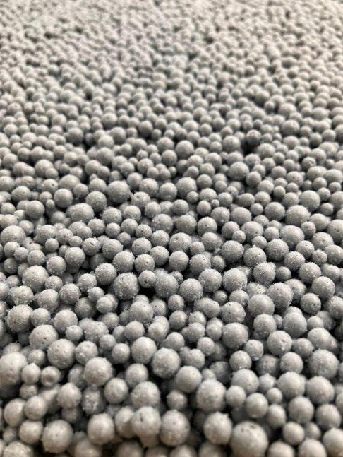
energystore spacebead® EPS beads 2 to 8 mm diameter, grey, spherical EPS beads bonding adhesive white, water-based synthetic adhesive aerogel 1 to 2 mm silica aerogel particles
2.1.2 Ancillary items falling outside the scope of this Agrément
The following ancillary items detailed in this Section may be used in conjunction with the System, but fall outside the scope of this Agrément:
• masonry wall;
• structural timber-framed supporting wall (‘STF’);
• vapour control layer (hereinafter ‘VCL’);
• plasterboard lining;
• sheathing board;
• drilling machine;
• breather membrane;
• blowing machine and application equipment;
• pre-existing insulation within the cavity (if present);
• VCL tape;
• weepholes and weep vents;
• finishes.
2.2 POINTS OF ATTENTION TO THE SPECIFIER
2.2.1 Design
2.2.1.1 Design responsibility
Project-specific design is the responsibility of an Approved Installer, trained and approved by the Agrément holder.
2.2.1.2 Basis of design
The characteristics detailed in the section titled ‘Major Points of Assessment’ shall be considered during the use of the System
2.2.1.3 General design considerations
The System may be used in walls up to 12 m in height (or above, where the Agrément holder has issued a suitable waiver), in non- residential buildings or when installed in a cavity construction comprising two masonry leaves, each at least 75 mm thick, subject to reaction to fire height restrictions in accordance with national Building Regulations - see Section 2.2.8
Buildings incorporating the System shall be designed and constructed in accordance with:
• BS EN 845-1;
• BS EN 14081-1;
• BS EN 1992-1-1 / I.S. EN 1992-1-1;
• BS EN 1995-1-1 / I.S. EN 1995-1-1;
• BS EN 1996-1-1 / I.S. EN 1996-1-1;
• BS EN 1996-1-2 / I.S. EN 1996-1-2;
• BS EN 1996-2 / I.S. EN 1996-2;
• BS EN 1996-3 / I.S. EN 1996-3;
• BS 8000-3;
• PD 6693-1;
• PD 6697.
The target mean density of the installed System is 18 kg/m3. Individual areas within the wall shall not have a density variation of more than ± 3 kg/m3 from the target mean density.
The minimum cavity width to be filled with the System shall be 50 mm for new buildings and 40 mm for existing buildings.
The guidance given in BRE Report 262 shall be followed in connection with the weathertightness of wall constructions. The Specifier shall select a construction appropriate to the local wind-driven rain index in accordance with BS 8104 and exposure zones in accordance with PD 6697, paying due regard to the design detailing, workmanship and materials to be used. Installation of the System shall not be undertaken until the supporting wall is weathertight, i.e. the roof is in place and the window and door openings are sealed.
The Specifier shall determine the suitability of the System to be used on walls in the specific exposure zone detailed in BRE Report 262 on a project-specific basis, with the appropriate local wind-driven rain index, in accordance with BS 8104.
Care is needed for design detailing of joints around openings, penetrations, wall corners and movement joints, which shall be in accordance with BS 6093 and shall incorporate cavity barrier, cavity closer, damp-proof course (hereinafter ‘DPC’), as required.
Care shall be taken in the overall design and construction of junctions with other elements and openings to minimise thermal bridges and air infiltration.
Ventilation openings shall be arranged to prevent the ingress of rain, snow, birds and small animals, and reduce the risk of blockage by other building operations.
External masonry cavity walls shall be constructed in accordance with the national Building Regulations. Ensure the activities that form part of the pre installation survey have been fulfilled - see Section 2.4.1.
The System can be installed on structural timber-framed supporting walls, where sheathing consists of exterior-grade cement-bonded particle boards (hereinafter ‘CBPB’), marine-grade plywood, oriented strand boards (hereinafter ‘OSB’) or fibre cement boards. Manufacturing requirements are as follows:
• CBPB shall be manufactured in accordance with BS EN 12467 or BS EN 634-2, with a minimum thickness of 10 mm;
• marine-grade plywood shall be manufactured in accordance with BS EN 313-1, with a minimum thickness of 12 mm;
• OSB shall be OSB/3, manufactured in accordance with BS EN 300, with a minimum thickness of 9 mm;
• fibre cement boards shall be weather resistance Category A or B and bending strength Class 2 or 3, manufactured in accordance with BS EN 12467, with a minimum thickness of 9 mm.
Timber-framed walls shall:
• have typical dimensions of at least 140 mm thick, with a minimum width of 75 mm;
• maintain a clear cavity between the external masonry and the timber frame , ensuring adequate air circulation and preventing water to cross the cavity; a suitable breather membrane sh all be placed across the timber facing the external masonry wall to provide protection of the inner wall against water ingress;
• have a cavity of 400 mm or 600 mm wide sections between solid timber studs (but often have small widths around openings);
• incorporate a VCL on the internal face of the timber framed inner leaf to ensure that the moisture content of the timber is kept at or below 20 %, and to ensure the air tightness of the building.
2.2.1.4 Project-specific design considerations
The project-specific design shall:
• be determined by the Specifier;
• consider the exposure zones where the System is installed;
• take into account the requirements of the relevant national Building Regulations - see Section 3.2;
• take into account the service life durability required - see Section 2.2.11
A pre-installation survey is required to allow determination of the project-specific design - see Section 2.4.1
The Specifier shall ensure that the following considerations are included in the development of a project-specific design:
• structural adequacy of supporting wall;
• thermal transmittance (hereinafter ‘U-value’) requirements;
• condensation risk analysis requirements;
• design of cavity trays, weep holes, weep vents and DPC;
• adequacy of cavity fire barriers;
• drilling pattern appropriate for the specific type of building;
• resistance to the ingress of precipitation, moisture and dangerous gases from the ground.
2.2.2 Applied building physics (heat, air, moisture)
A Specialist shall check the hygrothermal behaviour of a project-specific design incorporating the System and, if necessary, offer advice on improvements to achieve the final specification. The Specialist can be either a qualified employee of the Agrément holder or a suitably quali fied consultant (in which case it is recommended that the Specialist co-operates closely with the Agrément holder).
2.2.3 Permitted applications
Only applications designed according to the specifications given in this Agrément are permitted. In each case, the Specifier and Installer shall co- operate closely with the Agrément holder.
2.2.4 Installer competence level
The System shall be installed strictly in accordance with the instructions of the Agrément holder and the requirements of this Agrément.
Installation shall be by employees trained and approved by the Agrément holder and subject to inspections by Kiwa Ltd. under a Kiwa Installation Assessment & Surveillance Scheme.
2.2.5 Delivery, storage and site handling
The System components are delivered in suitable packaging bearing relevant identification information (such as the System name, production identification date or batch number, the Agrément holder’s name, etc.) and, where applicable, the BDA Agrément® logo incorporating the number of this Agrément.
Prior to installation, the System components shall be stored in accordance with the Agrément holder’s requirements. Good housekeeping protocols shall be followed to avoid damage. In particular, the System components shall be:
• kept dry and in well-ventilated areas, away from heat/ignition sources;
• protected from direct sunlight, rain, frost and humidity;
• stored in tightly-sealed container. Once opened, content should be used as soon as possible;
• handled wearing suitable personal protective equipment;
• kept in original packaging until ready for use
2.2.6 Maintenance and repair
Once installed, the System does not require regular maintenance. For advice in respect of repair, consult the Agrément holder.
Performance factors in relation to the Major Points of Assessment
2.2.7 Moisture control
Condensation risk
The performance of the System, in relation to water vapour permeability is detailed in Section 2.5.1
External walls incorporating the System will adequately limit the risk of surface and interstitial condensation when designed in accordance with BS 5250 and the national Building Regulations
A condensation risk analysis is required and shall be completed at the project-specific design stage for all elements of the construction, including at junctions, openings and penetrations, to minimise the risk of surface and interstitial condensation.
Water absorption
When installed in accordance with this Agrément, the System will provide protection against water bridging the cavity from the outer leaf to the inner leaf.
The System does not absorb water by capillary action and can be used where it bridges the DPC in walls. Moisture from the ground will not pass through to the inner leaf, providing that the wall is correctly detailed in accordance with the requirements of the national Building Regulations
2.2.8 Fire performance
The System is classified as European Classification F, in accordance with BS EN 13501-1.
For all buildings in Wales and Northern Ireland, and non-residential buildings in England, the following applies in accordance with the national Building Regulations:
• the System shall not be used on buildings with a storey of 18 m or more above ground level. Refer to the relevant national Building Regulations for types of buildings and any exclusions that may apply;
• boundary restrictions may apply, dependent on the external surface materials of the external wall incorporating the System, facing the boundary.
For residential buildings in England, the following applies in accordance with the national Building Regulations:
• the System is restricted to buildings with no floor more than 11 m above ground level. Refer to the national Building Regulations for types of buildings and any exclusions that may apply;
• boundary restrictions may apply, dependent on the external surface materials of the external wall incorporating the System, facing the boundary.
For all buildings in Scotland, the System is not classified as ‘non-combustible’ and is restricted to buildings with no floor more than 11 m above ground level and not less than 1 m from the boundary. In such cases, the System may be excluded from the unprotected area calculation regardless of openings. Refer to the national Building Regulations for types of buildings and any exclusions that may apply.
For dwellings in Ireland, the System is restricted to buildings with no floor more than 15 m above ground level. Refer to the national Building Regulations for types of buildings and any exclusions that may apply;
For buildings other than dwellings in Ireland, the System is restricted to buildings with no floor more than 18 m above ground level. Refer to the national Building Regulations for types of buildings and any exclusions that may apply.
The restrictions outlined above in terms of height above ground level and proximity to boundary do not apply, provided the System is installed in a cavity construction comprising two masonry leaves, each at least 75 mm thick, and with cavities closed around openings in a wall and at the top of a wall head.
The fire resistance of walls is based on the occupancy, size and use of a building and shall be a minimum of 30 minutes. It i s then specified in 30-minute intervals thereafter.
Walls shall be designed and constructed:
• to adequately resist the passage and penetration of fire;
• so that the unseen spread of fire and smoke with concealed spaces in a wall is inhibited.
In all completed wall constructions, cavity fire barriers shall be provided to comply with the relevant provisions of the national Building Regulations.
Care shall be taken to ensure continuity of fire resistance at junctions, around openings and service penetrations with fire- resisting elements, in accordance with the national Building Regulations.
Designers shall refer to the relevant national Building Regulations and guidance for detailed conditions of use This is particularly relevant to requirements for supporting wall fire performance, cavity closers and fire stopping of service penetrations, and combustibility limitations for other materials and components used in the overall wall construction.
Proximity of flues and appliances
The installed System shall be adequately separated from any chimney, heat producing appliance or incinerator flue pipe passing through a wall. Rec ommended means of separation are detailed in the Approved Documents supporting the national Building Regulations.
2.2.9 Thermal performance
For the purpose of U-value calculations and to determine if the requirements of national Building (or other statutory) Regulations are met, the thermal resistance and U-value of external cavity walls incorporating the System shall be calculated in accordance with BS EN ISO 10211 (taking into consideration BS EN ISO 6946, BS 5250, BRE Report 443, PAS 2030 and PAS 2035), using the declared aged thermal conductivity (λD).
Care shall be taken in the overall design and construction of junctions with other elements and openings to minimise thermal bridges and air infiltration.
Guidance on linear thermal transmittance, heat flows and surface temperature factors can be found in the documents supporting the national Building Regulations and in BS EN ISO 10211, BRE Information Paper 1/06, BRE Report 262, BRE Report 497 and PAS 2030. If required, further information can be provided by the Agrément holder.
The requirement for limiting heat loss through the building fabric, including the effect of thermal bridging, can be satisfied if the U-value of a wall incorporating the System does not exceed the maximum U-values given in the national Building Regulations
2.2.10 Adequacy of fill
A cavity can be fully filled with the System (with no voids/gaps and a consistent density) including around details.
Care shall be taken in difficult-to-fill areas of a cavity wall, e.g. corners, to ensure that the cavity is sufficiently filled with the System.
2.2.11 Durability
The System shall have a service life durability equivalent to that of the building into which it is incorporated. The expected lifespan of the building itself shall be at least 60 years.
Once installed, the System is not susceptible to damage from environmental conditions normally encountered in the UK and Ireland
2.2.12 UKCA, UKNI and CE marking
The British and European standard for the System is BS EN 16809 (parts 1 and 2).
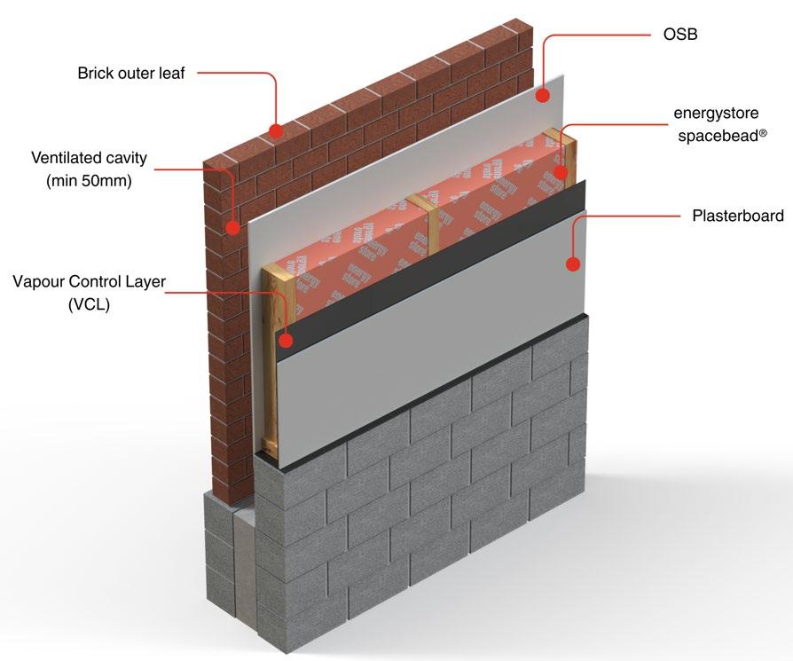
2.3 EXAMPLES OF TYPICAL DETAILS
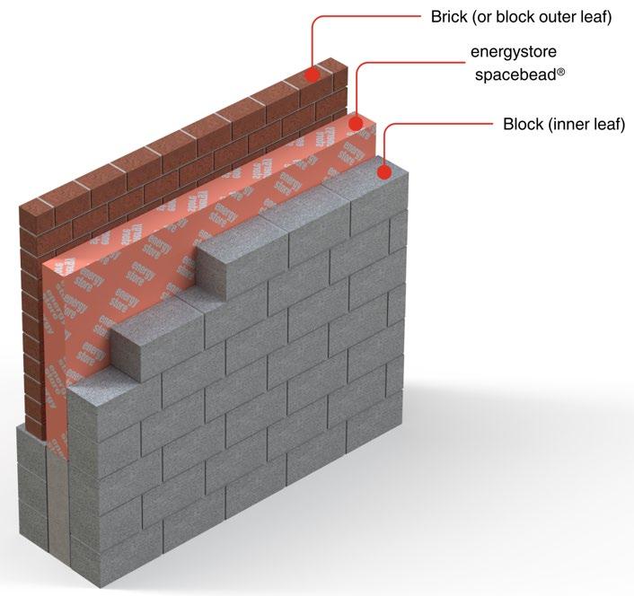
Diagram 1 - Typical detail of the System installed in a full-fill application in masonry wall
Diagram 2 - Typical detail of the System installed in a timber-framed application
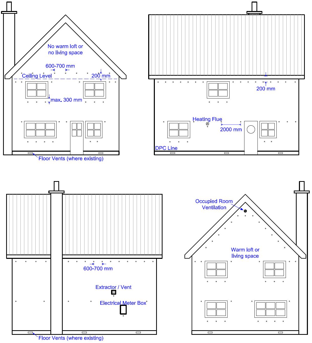
3 - Drilling pattern for full fill external masonry cavity walls
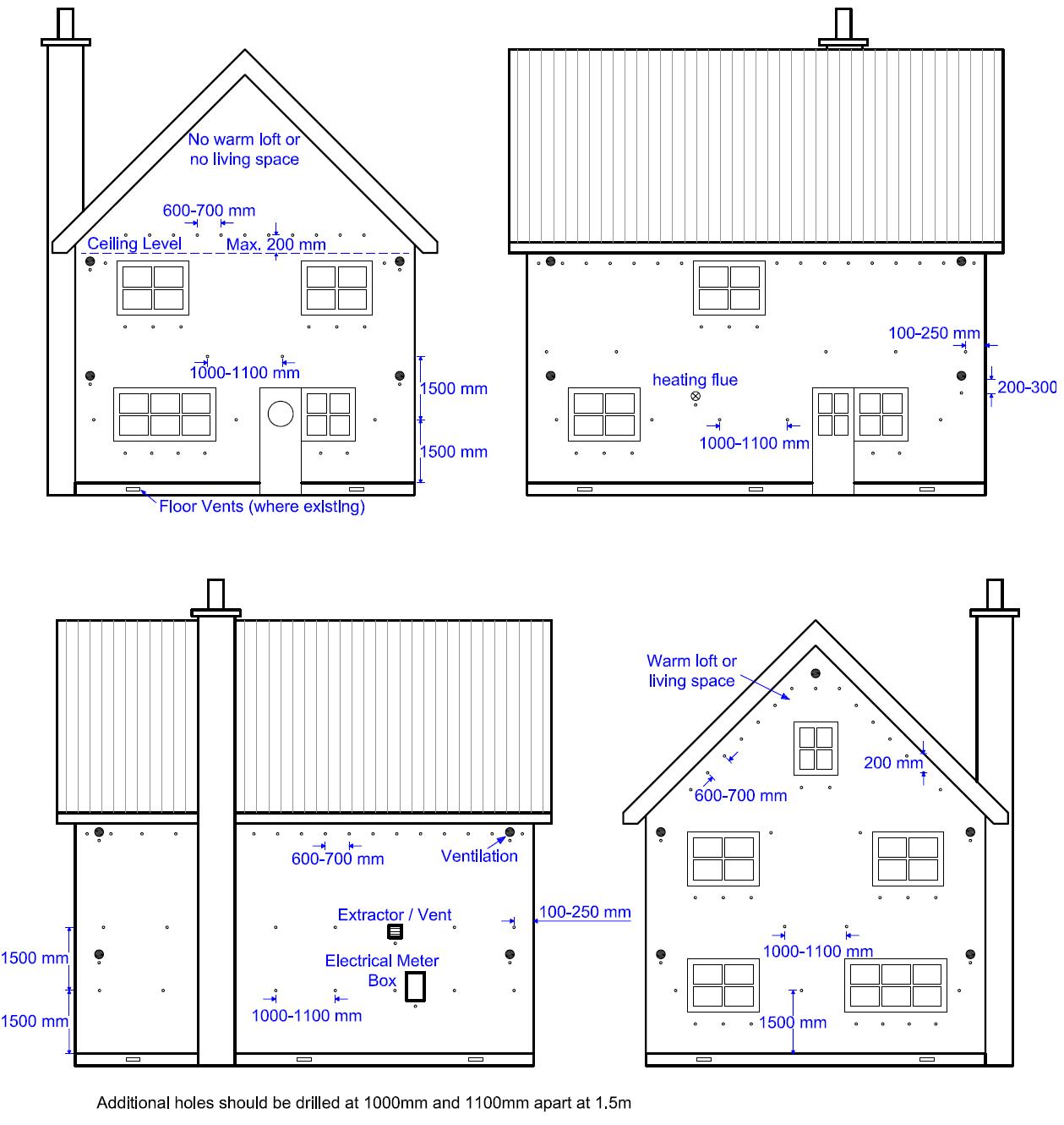
4 - Drilling pattern for partial fill external masonry cavity walls
Diagram
Diagram
2.4 INSTALLATION
The System shall be installed strictly in accordance with the instructions (hereinafter ‘Installation Manual’) of the Agrément holder , the requirements of this Agrément and the requirements of BS 8000-0.
2.4.1 Project-specific installation considerations
The project-specific design shall be determined from a pre-installation survey.
The primary requirement of the pre-installation survey is to determine the following:
• the external wall construction is suitable for the installation of the System;
• any pre-existing insulation within the cavity is:
o compatible with the System, in accordance with the Installation Manual;
o in the correct position and in good condition;
• the cavity is weathertight, i.e. the roof is in place and that all cavity openings, such as those around doors and windows, are sealed;
• there is no existing rain ingress and no signs of damp on the internal face of the wall, other than that caused by condensati on;
• the external walls are in a good state of repair and show no evidence of frost damage;
• the cavity is free from blockages such as debris or mortar droppings;
• the walls are free from moisture, cracks and any defects;
• the presence of any penetrations in the walls such services, boilers, stoves, chimneys, flues or ventilators is identified; flues, chimneys and combustion air ventilators must be pre-inspected and tested in accordance with IAA Flues, Chimneys and Combustion Air Ventilators Manual;
• the width of the cavity and any variations are verified;
• the DPC positions at window and door heads are checked
2.4.2 Preparation
The following considerations apply before starting the work:
• essential ventilation openings and all flues in the cavity wall shall be checked. If adequate sleeving or other cavity closures are not present, installation shall not proceed until these openings have been sleeved or otherwise modified to prevent blockage by the System;
• the drilling pattern is dependent on the type and configuration of building;
• ensure plastering has not started before the installation of the System ;
• ensure the requirements of CIGA/IAA industry guidance and associated literature are followed;
• appropriate personal protective equipment (dust suit, face mask and goggles) shall be worn during installation.
The following works shall be undertaken before installing the System:
• any gaps shall be effectively sealed to reduce air infiltration;
• if necessary, reroute trunk services e.g. electrical cables;
• window, door and other openings shall be sealed as necessary;
• borescope inspections shall be carried out to determine whether any pre- existing insulation is present and to verify the existence of clear cavities;
• where the wall includes bridging features such as boiler flues, service boxes, waste pipes etc., additional documented borescope checks are required;
• the integrity of cavity trays, any membrane and weepholes shall be checked;
• cavity brushes shall be installed as required;
• any electrical cables shall be marked on drawings and enclosed in suitable conduit;
• a comprehensive site survey report shall be completed.
2.4.3 Outline installation procedure
Detailed installation procedures can be found in the Agrément holder’s Installation Manual.
The outline procedure is as follows:
Drilling:
Masonry walls:
• drill from the external face into the outer masonry leaf using light pressure to minimise debris falling into cavity;
• drill 22 to 26 mm diameter injection clearance holes into the mortar joints of the outer leaf; refer to Installation Manual for the recommended drilling patterns;
• allow 600 to 650 mm spacing centres horizontally and 200 mm above the highest ceiling level; additional drill holes may be required to ensure complete filling around building features, e.g. under window cills and between doors and windows. Care shall be taken to ensure that drill holes do not coincide with any intermediate suspended timber floor;
• for two-storey buildings, drill an additional level of drill holes at 1,000 to 1,100 mm centres, 1,500 mm from the DPC level, and at 3,000 mm from the DPC level Care shall be taken to ensure that drill holes do not coincide with any intermediate suspended timber floor.
Timber-framed walls:
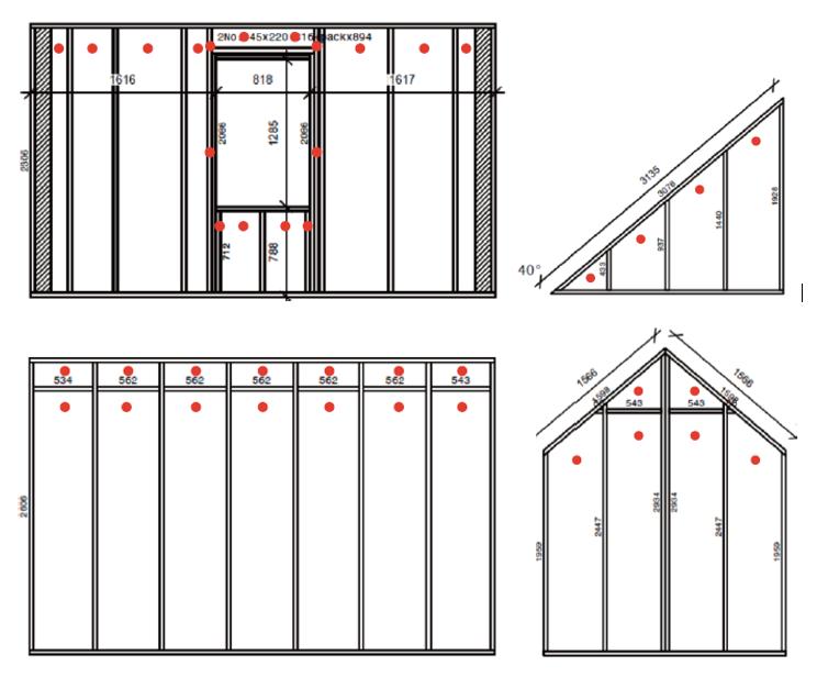
• drill from the internal face into the plasterboard core holes of 75 mm in diameter, drilling each plasterboard centrally and 100 to 150 mm from the top of each plasterboard section. Holes shall be aligned horizontally with the centre of the plasterboard, with a single hole per panel, with the exception of panels that are more than 1,500 mm in height and less than 50 mm in width. These panels shall have two drill holes, the first 100 mm from the top of the cavity, and the second halfway down the cavity;
• use the drill stop set to the depth of the plasterboard at all times to prevent unnecessary cuts into the VCL;
• drill with light pressure to minimise undue damage to the plasterboard;
• cut no larger than 22 mm holes in the VCL to allow the nozzle through the VCL
Quality check:
The following quality aspects shall be checked before the filling procedure commences:
• existence and identification of clear cavities and any services within the cavity through borescope inspections (minimum of three tests per level);
• density of the EPS beads, checked using a hessian bag;
• flow rate of the aerogel, checked using a test box;
• a test of the pressure switch on the injection machine;
• a check of the pressure bars on the installing van.
Once the correct bead/aerogel flow rate has been achieved, the appropriate adhesive flow rate shall be selected
Filling procedures:
The following procedures are undertaken during the filling process:
• starting from the lowest drilling level of the building, insert the injection gun nozzle fully into the injection hole;
• open the airflow valve and once bead flow is evident in the bead hose, open the adhesive and aerogel valves ;
• maintain both valves open until back pressure is detected (the sound of the airflow may change), at which point both valves shall be closed;
• move the nozzle to the next drilling hole on the current level and repeat the injection process;
• upon completion of all the drilling holes on the current level, proceed to the next drilling level up until the top drilling level has been completed.
2.4.4 Finishing
The following finishing is required on completion of the installation:
• ensure that installed density of the System is correct, as per specifications;
• ensure no material blockage is present and and that no damage has occurred to the building;
• all combustion air ducts and trunked air vents (e.g. those providing underfloor ventilation and combustion air for heating appliances ) are checked and any obstructions cleared; flues, chimneys and combustion air ventilators must be post-inspected and tested in accordance with IAA Flues, Chimneys and Combustion Air Ventilators Manual;
• inspect the adequacy of installation as per the Installation Manual, checking that all drill holes are filled, no tools remaining and that all vents and chimneys are working and clear;
• clean up any spilled material or debris;
• for masonry walls, seal and point the injection holes with appropriate mortar of a similar type, colour, texture to that of the existing wall;
• for timber-framed walls, ensure the VCL is resealed using suitable tape, and the original core is replaced using a drywall repair clip. The core is then covered with adhesive scrim prior to plastering;
• carry out a final inspection and complete sign-off report.
2.5.1 Moisture control
2.5 INDEPENDENTLY ASSESSED SYSTEM CHARACTERISTICS
Test Standard
Short-term water absorption by partial immersion (Wp)
Water vapour resistance factor (μ) of loose-fill EPS beads
2.5.2 Fire performance
Result
BS EN ISO 29767 Method A < 1 kg/m2
BS EN ISO 10456
Test Standard
Reaction to fire classification
2.5.3 Thermal performance
Result
BS EN 13501-1 F
Test Standard
Declared aged thermal conductivity (λD)
2.5.4 Other System characteristics
Result
BS EN 12667 0.029 W/mK
Test Standard Result
Density
BS EN 1602 18 ± 3 kg/m3
3.1 THE CONSTRUCTION (DESIGN AND MANAGEMENT) REGULATIONS 2015 AND THE CONSTRUCTION (DESIGN AND MANAGEMENT) REGULATIONS (NORTHERN IRELAND) 2016
Information in this Agrément may assist the client, principal designer/CDM co-ordinator, designer and contractors to address their obligations under these Regulations.
3.2
THE NATIONAL BUILDING REGULATIONS
In the opinion of Kiwa Ltd., the System, if installed and used in accordance with Section 2 of this Agrément, can satisfy or contribute to satisfying the relevant requirements of the following national Building Regulations.
This Agrément shall not be construed to confer the compliance of any project-specific design with the national Building Regulations.
3.2.1 England
The Building Regulations 2010 and subsequent amendments
• B3(4) Internal fire spread (structure) - a wall incorporating the System can inhibit the unseen spread of fire and smoke within concealed spaces
• C2(a) Resistance to ground moisture - the System does not absorb water by capillary action
• C2(b) Resistance to precipitation moisture - a wall incorporating the System can resist precipitation and satisfy this Requirement
• C2(c) Resistance to condensation moisture - the System can contribute to satisfying this Requirement
• L1(a)(i) Conservation of fuel and power - the System can contribute to limiting heat gains and losses through a wall
• Regulation 7(1) Materials and workmanship - the System is manufactured from suitably safe and durable materials for its application and can be installed to give a satisfactory performance
• Regulation 23 Requirements relating to thermal elements - the System can contribute to a wall complying with the requirements of L1(a)(i)
• Regulation 26 CO2 emission rates for new buildings - the System can contribute to satisfying this Requirement
• Regulation 26A Fabric energy efficiency rates for new dwellings - the System can contribute to satisfying this Requirement
• Regulation 26C Target primary energy rates for new buildings - the System can contribute to satisfying this Requirement
3.2.2 Wales
The Building Regulations 2010 and subsequent amendments
• B3(4) Internal fire spread (structure) - a wall incorporating the System can inhibit the unseen spread of fire and smoke within concealed spaces
• C2(a) Resistance to ground moisture - the System does not absorb water by capillary action
• C2(b) Resistance to precipitation moisture - a wall incorporating the System can resist precipitation to the inner leaf and satisfy this Requirement
• C2(c) Resistance to condensation moisture - the System can contribute to satisfying this Requirement
• L1(a)(i) Conservation of fuel and power - the System can contribute to limiting heat gains and losses through a wall
• Regulation 7(1) Materials and workmanship - the System is manufactured from suitably safe and durable materials for its application and can be installed to give a satisfactory performance
• Regulation 23 Requirements relating to thermal elements - the System can contribute to a wall complying with the requirements of L1(a)(i)
• Regulation 26 CO2 emission rates for new buildings - the System can contribute to satisfying this Requirement
• Regulation 26A Primary energy rates for new buildings - the System can contribute to satisfying this Requirement
• Regulation 26B Fabric performance values for new dwellings - the System can contribute to satisfying this Requirement
• Regulation 26C Energy efficiency rating - the System can contribute to satisfying this Requirement
3.2.3 Scotland
The Building (Scotland) Regulations 2004 and subsequent amendments
3.2.3.1 Regulation 8 (1)(2) Durability, workmanship and fitness of materials
• The System is manufactured from acceptable materials and is considered to be adequately resistant to deterioration and wear under normal service conditions, provided it is installed in accordance with the requirements of this Agrément
3.2.3.2 Regulation 9 Building Standards - Construction
• 2.4 Cavities - a wall incorporating the System can inhibit the unseen spread of fire and smoke within concealed spaces
• 3.4 Moisture from the ground - the System does not absorb water by capillary action
• 3.10 Precipitation - a wall incorporating the System can resist precipitation to the inner leaf and satisfy this Requirement
• 3.15 Condensation - a wall incorporating the System can be designed and constructed to limiting the risk of surface and interstitial condensation
• 6.2 Building insulation envelope - the System can contribute to limiting heat gains and losses through a wall
• 7.1(a)(b) Statement of sustainability - the System is manufactured from materials that can contribute to satisfying the relevant requirements of Regulation 9, Standards 1 to 6, and therefore will contribute to a construction meeting a bronze level of sustainability as defined in this Standard; in addition, the System can contribute to a construction meeting a higher level of sustainability as defined in this Standard
3.2.3.3 Regulation 12 Building Standards - Conversions
• All comments given under Regulation 9 also apply to this regulation, with reference to Schedule 6 of The Building (Scotland) Regulations 2004 and subsequent amendments, clause 0.12 of the Technical Handbook (Domestic) and clause 0.12 of the Technical handbook (Non- Domestic)
3.2.4 Northern Ireland
The Building Regulations (Northern Ireland) 2012 and subsequent amendments
• 23(1)(a)(i)(ii)(iii)(b) Fitness of materials and workmanship - the System is manufactured from materials which are considered to be suitably safe and acceptable for use as described in this Agrément
• 28(a) Resistance to moisture and weather - the System does not absorb water by capillary action
• 28(b) Resistance to moisture and weather - a wall incorporating the System can resist precipitation to the inner leaf and satisfy this Requirement
• 29 Condensation - a wall incorporating the System can be designed and constructed to prevent interstitial condensation
• 35(4) Internal fire spread - Structure - a wall incorporating the System can inhibit the unseen spread of fire and smoke within concealed spaces
• 39(a)(i) Conservation measures - the System can contribute to limiting heat gains and losses through a wall
• 40(2) Target carbon dioxide emission rate - a wall incorporating the System shall be designed and constructed as not to exceed its target CO2 emission rate
• 43 Renovation of thermal elements - the renovation work carried out to ensure the wall complies with requirement 39(a)(i)
3.2.5 Ireland
Building Regulations 1997 and subsequent amendments
In order to demonstrate compliance with Irish Building Regulations, this BDA Agrément® certifies that the System complies with the requirements of a recognised document and indicates it is suitable for its’ intended purpose and use.
• B3(3) Internal fire spread (structure, for buildings other than dwellings) - a wall incorporating the System can inhibit the unseen spread of fire and smoke within concealed spaces
• B8(3) Internal fire spread (structure, for dwelling houses) - a wall incorporating the System can inhibit the unseen spread of fire and smoke within concealed spaces
• C4 Resistance to weather and ground moisture - a wall incorporating the System can contribute to adequately protecting a building from the passage of moisture from precipitation and condensation
• D1 Materials and workmanship - the System is manufactured from suitably safe and durable materials for their application, and can be installed to give a satisfactory performance
• L1 Conservation of fuel and energy - the System can contribute to limiting heat gains and losses through walls
• L2(a) Conservation of fuel and energy (in existing dwellings) - the System can contribute to limiting heat gains and losses through walls
• L4(a) Conservation of fuel and energy (in existing buildings other than dwellings) - the System can contribute to limiting heat gains and losses through walls
• L5(c) Conservation of fuel and energy (in new buildings other than dwellings) - the System can contribute to limiting heat gains and losses through walls
• Regulation 7 Conservation of fuel and energy in existing dwellings - the System can contribute to satisfying this Requirement
• Regulation 8(c) Conservation of fuel and energy in new dwellings - the System can contribute to satisfying this Requirement
3.3 THIRD-PARTY ACCEPTANCE
In the opinion of Kiwa Ltd. if installed, used, and maintained in accordance with this Agrément, this System can satisfy the appropriate structural, fire, moisture, thermal, acoustic and durability requirements of a Structural Warranty provider. Please contact the relevant Structural Warranty provider to ascertain their project specific design requirements and to confirm their acceptance on a case- by-case basis.
4 SOURCES
• BS EN ISO 6946:2017 Building components and building elements. Thermal resistance and thermal transmittance. Calculation meth ods
• BS EN ISO 9001:2015+A1 2024 Quality management systems. Requirements
• BS EN ISO 10211:2017 Thermal bridges in building construction. Heat flows and surface temperatures. Detailed calculations
• BS EN ISO 10456:2007 Building materials and products. Tabulated design values and procedures for determining declared and design thermal values
• BS EN ISO 29767:2019 Thermal insulating products for building applications. Determination of short-term water absorption by partial immersion
• BS EN 300:2006 Oriented strand boards (OSB). Definitions, classification and specifications
• BS EN 313-1:1996 Plywood. Classification and terminology. Plywood. Classification and terminology. Classification
• BS EN 634-2:2007 Cement-bonded particleboards. Specifications. Requirements for OPC bonded particleboards for use in dry, humid and external conditions
• BS EN 845-1:2013+A1:2016 Specification for ancillary components for masonry-Wall ties, tension straps, hangers and brackets
• BS EN 1602:2013 Thermal insulating products for building applications. Determination of the apparent density
• BS EN 1992-1-1:2004+A1:2014 Eurocode 2: Design of concrete structures. General rules and rules for buildings
• NA+A2:2014 to BS EN 1992-1-1:2004+A1:2014 UK National Annex to Eurocode 2. Design of concrete structures. General rules and rules for buildings
• BS EN 1995-1-1:2004+A2:2014 Eurocode 5: Design of timber structures. General. Common rules and rules for buildings
• NA to BS EN 1995-1-1:2004+A2:2014 UK National Annex to Eurocode 5: Design of timber structures. General. Common rules and rules for buildings
• BS EN 1996-1-1:2005+A1:2012 Eurocode 6. Design of masonry structures. General rules for reinforced and unreinforced masonry
• NA to BS EN 1996-1-1:2005+A1:2012 Eurocode 6. Design of masonry structures. General rules for reinforced and unreinforced masonry
• BS EN 1996-1-2:2005 Eurocode 6. Design of masonry structures. Structural fire design
• NA to BS EN 1996-1-2:2005 UK National Annex to Eurocode 6. Design of masonry structures. Structural fire design
• BS EN 1996-2:2006 Eurocode 6. Design of masonry structures. Design considerations, selection of materials and execution of masonry
• NA to BS EN 1996-2:2006 UK National Annex to Eurocode 6. Design of masonry structures. Design considerations, selection of materials and execution of masonry
• BS EN 1996-3:2006 Eurocode 6. Design of masonry structures. Simplified calculation methods for unreinforced masonry structures
• NA+A1:2014 to BS EN 1996-3:2006 UK National Annex to Eurocode 6. Design of masonry structures. Simplified calculation methods for unreinforced masonry structures
• BS EN 12467:2012+A2:2018 Fibre-cement flat sheets. Product specification and test methods
• BS EN 12667:2001 Thermal performance of building materials and products. Determination of thermal resistance by means of guar ded hot plate and heat flow meter methods. Products of high and medium thermal resistance
• BS EN 13501-1:2018 Fire classification of construction products and building elements. Classification using data from reaction to fire tests
• BS EN 14081-1:2016+A1:2019 Timber structures. Strength graded structural timber with rectangular cross section. General requirements
• BS EN 16809-1:2019 Thermal insulation products of buildings. In- situ formed products from loose-fill expanded polystyrene (EPS) beads and bonded expanded polystyrene beads - Specification for the bonded and loose-fill products before installation
• BS EN 16809-2:2007 Thermal insulation products of buildings. In- situ formed products from loose-fill expanded polystyrene (EPS) beads and bonded expanded polystyrene beads - Specification for the bonded and loose-fill products after installation
• BS 5250:2021 Management of moisture in buildings. Code of practice
• BS 6093:2006+A1:2013 Design of joints and jointing in building construction. Guide
• BS 8000-0:2014+A1:2024 Workmanship on construction sites. Introduction and general principles
• BS 8000-3:2020 Workmanship on construction sites-Masonry. Code of practice
• BS 8104:1992 Code of practice for assessing exposure of walls to wind-driven rain
• BRE Information Paper 1/06:2006 Assessing the effects of thermal bridging at junctions and around openings
• BRE Report 262:2002 Thermal insulation: avoiding risks
• BRE Report 443:2019 Conventions for U-value calculations
• BRE Report 497:2016 Conventions for calculating linear thermal transmittance and temperature factors
• IAA Flues, Chimneys and Combustion Air Ventilators Manual: 2020
• I.S EN 1992-1-1:2004+AC:2010+A1:2014 Eurocode 2: Design of concrete structures. Part 1- 1: General rules and rules for buildings
• I.S. EN 1992-1-1/NA:2004/NA:2010/AC2:2020 Irish National Annex to Eurocode 2: Design of concrete structures. Part 1- 1: General rules and rules for buildings
• I.S. EN 1995-1-1:2005 Eurocode 5: Design of timber structures. Part 1-1: General. Common rules and rules for buildings
• I.S. EN 1995-1-1/NA:2005+A1:2013 Irish National Annex to Eurocode 5: Design of timber structures. Part 1- 1: General. Common rules and rules for buildings
• I.S. EN 1996-1-1:2005+A1:2012 Eurocode 6: Design of masonry structures. Part 1- 1: General rules for reinforced and unreinforced masonry structures
• I.S. EN 1996-1-1+A1:2012/NA:2010+A1:2014 Irish National Annex to Eurocode 6: Design of masonry structures. Part 1- 1: General rules for reinforced and unreinforced masonry structures
• I.S. EN 1996-1-2:2005 Eurocode 6: Design of masonry structures. Part 1-2: General rules. Structural fire design
• I.S. EN 1996-1-2/NA:2005 Irish National Annex to Eurocode 6: Design of masonry structures. Part 1- 2: General rules. Structural fire design
• I.S. EN 1996-2:2006 Eurocode 6: Design of masonry structures. Part 2: Design considerations, selection of materials and execution of masonry
• I.S. EN 1996-2/NA:2006 Irish National Annex to Eurocode 6: Design of masonry structures. Part 2: Design considerations, selection of materials and execution of masonry
• I.S. EN 1996-3:2006 Eurocode 6: Design of masonry structures. Part 3: Simplified calculation methods for unreinforced masonry structures
• I.S. EN 1996-3/NA:2006 Irish National Annex to Eurocode 6: Design of masonry structures. Part 3: Simplified calculation methods for unreinforced masonry structures
• PAS 2030:2023 Installation of energy efficiency measures in existing dwellings. Specification
• PAS 2035:2023 Retrofitting dwellings for improved energy efficiency. Specification and guidance
• PD 6693-1:2025 Recommendations for the design of timber structures to Eurocode 5: Design of timber structures General. Common rules and rules for buildings
• PD 6697:2019 Recommendations for the design of masonry structures to BS EN 1996-1-1 and BS EN 1996-2
Remark - Apart from these sources, technical information and confidential reports have been assessed; any relevant documents are in the possession of Kiwa Ltd. and are kept in the Technical Assessment File of this Agrément. The Installation Manual for the System may be subject to change; contact the Agrément holder for the clarification of revisions.
5 AMENDMENT HISTORY
Revision
Amendment description
Author Approver Date - First issue L Tosi C Devine November 2025
6 CONDITIONS OF USE
This Agrément may only be reproduced and distributed in its entirety.
Where a National Annex exists in respect of a BS EN (or other) standard, its use is deemed mandatory wherever the original standard is referenced.
Kiwa Ltd. has used due skill, care and attention in the preparation of this BDA Agrément®
Whilst all due diligence has been used, no liability or warranty is extended by Kiwa Ltd.
The Agrément holder is responsible for advising Kiwa Ltd. immediately if there is a variation to the System specification or constituent elements/components after initial publication of this BDA Agrément®
For full terms and conditions, refer to Kiwa Ltd.