Vacuum Tubes
A Practical Guide to Tube Electronics







Gerd Weichhaus














Gerd Weichhaus
Gerd Weichhaus
● © Copyright 2026 Elektor International Media 1st edition 2026
● All rights reserved.
The contributions published in this book, in particular all essays and articles, as well as all designs, plans, drawings, and illustrations, are protected by copyright. Their reproduction and distribution, even in part, is generally only permitted with the prior written consent of the publisher.
The information in this book is published without regard to any potential patent protection. Software and hardware designations mentioned in this book may be registered trademarks, even if not specifically indicated. They belong to their respective trademark holders and are subject to legal regulations.
The greatest care has been taken in compiling the texts and illustrations. Nevertheless, errors cannot be completely ruled out. The publisher, editors, and author cannot assume any legal responsibility or liability whatsoever for incorrect information and its consequences. The publisher and author are grateful for notification of any errors.
The author, translator, and publisher have made every effort to ensure the accuracy of the information contained in this book. They accept no liability for any loss or damage caused by errors or omissions in this book, regardless of whether such errors or omissions are due to negligence, oversight, or any other cause, and hereby disclaim all liability to third parties.
● Cover design: Elektor, Aachen
Editor: Elektor Team
Printers: Ipskamp, Enschede, The Netherlands
● ISBN 978-3-89576-762-3 (Print) 978-3-89576-763-0 (eBook) 978-3-89576-764-7 (ePUB)
● Copyright 2026 Elektor International Media - www.elektor.com
● Disclaimer: The projects and procedures described in this book involve electronic circuits and, in particular, vacuum tube equipment, which may contain hazardous voltages. Many devices operate directly from the mains supply and can retain dangerous high voltages in charged capacitors even after they have been switched off. Improper handling may result in serious personal injury, damage to property, or destruction of equipment. The procedures described in this book should therefore only be carried out by readers who possess the necessary technical knowledge or who fully understand the associated risks.
Every effort has been made to ensure that the information, circuit descriptions, and recommendations in this book are accurate and reliable. However, no guarantee can be given that the contents are complete or free from errors. Any practical application of the information provided is entirely at the reader's own risk. The author accepts no liability for personal injury, property damage, financial loss, or any other damage arising directly or indirectly from the use of the information contained in this book, to the extent permitted by applicable law.
When restoring or repairing vintage electronic equipment, you may encounter materials and components that are now considered hazardous to health or the environment. Examples include certain insulation materials, tar based compounds, older capacitors, and other components containing potentially harmful substances. Always follow the applicable safety regulations and use appropriate protective equipment when handling such materials. Throughout this book, I refer to specific companies and products that I personally use. This is solely intended to provide a starting point for your own decisions. There are always alternative products that may be better suited to your particular application. For the avoidance of doubt, I have never received, and will not receive, any commissions, gifts, or other incentives for mentioning any company, product, or service in this book.
Please familiarize yourself with the applicable regulations governing the disposal of any chemicals used or mentioned in this book, and ensure that all relevant legal requirements are followed. All photographs in this book were taken by me and depict circuit boards and equipment from my own collection.
Elektor is the world's leading source of essential technical information and electronics products for pro engineers, electronics designers, and the companies seeking to engage them. Each day, our international team develops and delivers high-quality content — via a variety of media channels (including magazines, video, digital media, and social media) in several languages — relating to electronics design and DIY electronics. www.elektormagazine.com
1.2
3.15.1 From the Control Grid to the Transistor
3.16 The Vacuum Tube and the Rise of
3.16.2 The Tube as Rectifier and Amplifier
3.16.3
4.1.5
4.1.7
4.3 The Different Socket Types and Their Characteristics
4.4
4.6 Tubes With Top Caps
4.7 Understanding
4.14
5.11
6.3 Astable Multivibrator for Audio Signal Generation
6.3.1 Construction Notes for the Audio Version
6.3.2 Audio Output
6.3.3 Heater and Operating Voltage
6.3.4 Sound Character and Use
6.3.5 Determining the Output Frequency
6.4 Adapted Circuits for Sound Synthesis
6.5 Sine Wave Oscillator Using the ECC81
6.6 Schmitt Trigger Using the ECC81
6.6.1 Function of the Potentiometer and LDR
6.6.2 Switching Behaviour Through Feedback
6.6.3 Example Application as a Twilight Switch
6.6.4 Significance of This Circuit
Chapter 7: Preamplifier and Amplifier Circuits
7.1
7.2 Phase Inversion in the Amplifier Stages
7.3 The Purpose of the Cathode Resistors and Bypass Capacitors
7.4 For Your Information: Linear Operation Through the Cathode Resistor
7.5 Heater Connections and Operating Voltage
7.6 Amplifying Microphone Signals With the ECC81
7.7
8.3
8.4
The Role of D1 and D2
The Screen Grid in the Pentode
8.4.2 A Further Note on the Output Transformer
8.4.3
8.4.4 What This Means for Circuit Design
8.4.5 Advantages and Disadvantages of the Output Transformer
8.5 When Tube Amplifiers Start to Oscillate: Beware of Unwanted Oscillations
8.6 Tube Output Stages Using the EL95, EL84, or ECL86
8.6.1 The Pentode in Triode Configuration
8.6.2 The Input Potentiometer: Linear and Logarithmic
8.7 Single-Ended Tube Amplifier Using the EL95
8.8 Single-Ended Tube Amplifier Using the ECL86
8.9 The Triode Stage for Voltage Amplification
8.10 The Pentode Stage and Power Amplification
8.11 Power Supply and Filtering
8.12 Sonic and Technical Characteristics .
8.13 Ground and Wiring Layout
8.14 Important Points Regarding Capacitors: Voltage Rating, ESR, and Ageing
8.15 A Brief Note on ESR
8.16 Resistors in the Supply Circuit: Function and Calculation
8.17 The Use of Bleeder and Discharge Resistors
8.18 Notes on Wiring the Cathode Heater Leads
8.19 Screening of Signal Leads and Correct Use of Shielding
8.20 Cable Bundling and Preventing Feedback
8.21 Further Relevant Notes .
Chapter 9: From Single-Ended to Push-Pull Amplifier
9.1 The Difference Lies in the Concept .
9.2 More Complexity, But Also More Capability
9.3 Simple Example Circuits for Getting
9.4 The Construction of a Push-Pull Tube Output Stage
9.4.1 Input and Phase Splitter Stage
9.4.2 The Phase Splitter
9.4.3 Why Is Phase Inversion Necessary at
The Push-Pull Output Stage
9.4.5 A Note on the
The Output to the Loudspeaker
Chapter 10: Power Supplies for Tube Circuits and Tube Equipment
10.1 Safety and Protection
10.2 Why Caution is Paramount
10.3 Safety Measures
10.4 Mains Transformer with Anode Voltage and Heater Voltage
10.5 The Windings for High Voltage and Heater
10.5.1 Insulation of the Mains Transformer
10.5.2 Dimensioning the Mains Transformer
10.5.3 A Brief Note on Volt-Amperes
10.6 Rectification: Tubes or Semiconductors?
10.6.1 Full-Wave Rectification Using Diodes
Bridge Rectifier vs. Centre-Tap Configuration
Advantages of Semiconductor Rectifiers: Efficient, Affordable, Compact
10.7 Using Tube Rectifiers
Voltage Drop and Warm-Up Time
10.8 Nostalgic Use and the Question of Sonic Character
The Influence of Rectifiers and Load Current
Reserve in the Dimensioning
The Diodes as One-Way
The Cascade of
Minimalist Solutions for Small
What Are Vibrators?
Why a Vibrator Is Needed
Chapter 11: Repairing Tube Equipment
11.2 Basic Safety Rules for Repair Work. .
11.3 Work Only With an Isolation Transformer and RCD
11.4 When a Device Should Be Checked by a Professional
11.5 Initial Assessment and Visual Inspection
11.6 Checking Cables, Contacts, and Wiring
11.7 Documenting the Repair Process
11.8 Brief Pre-Inspection Checklist
11.9 Before the First Power-Up
11.10 Do Not Apply Power Before Everything Has Been Checked
11.10.1 Check the Power Supply and Fuses First
11.10.2 Checking Capacitors, the Most Common Failure Points
11.10.3 Check Tubes for Obvious Damage
11.10.4 First Observations Without Measurements
11.10.5 Pre-Power-Up Checklist
11.11 Measurements and Preliminary Checks
11.11.2 Heater Pin Assignments
11.11.3 Testing the Mains Transformer Windings
11.11.4 Identifying Open Circuits in the Output Transformer
11.11.5 Testing Electrolytic and Other Capacitors for Short Circuits
11.11.6 Checking Fuses and Switches. .
Checking Socket Contacts and Solder Joints
11.12 Using an Isolation Transformer and Safety Tools
11.12.1 Why an Isolation Transformer Is Essential
11.12.2 What a Variable Autotransformer Is Good For
A Lamp Limiter as a Simple Current-Limiting Device
11.13 Slowly Bringing the Supply Voltage Up
11.13.1 Monitoring Current Draw and Voltages
11.13.2 Examples of Significant Deviations
Protecting the Power Supply and Tubes
11.13.4 Measuring Current Draw for Fault Diagnosis
Important:
11.14 Commissioning and Fault-Finding
Replacing and Adjusting Components
Which Components Should Typically Be Replaced
11.14.9 What to Watch for at First Power-Up
11.14.10 Being Alert to Sounds and Smells
11.14.11 Checking Sound Quality and Controls
11.14.12 Care With Aerials and External Connections
11.15 Tips for Lasting Repairs
11.15.1 Replacement Parts and Sourcing Components
11.15.2 Sensible Use of Modern Components in Old Equipment
11.15.3 Documentation and Care After the Repair
Chapter 12: The Typical Construction of Tube Equipment
12.1 What Is a Superhet and How Does It Work?
12.2 Why the Superhet Was Invented and What Didn‘t Work So Well With Straight Receivers
12.2.1 The Superhet Principle
12.2.2 FM Reception
12.2.3 AM Reception (Using Medium Wave as an Example)
12.3 The Functions of the Individual Tubes in the
12.4 The AGC Voltage in a Tube Radio:
12.4.1 How Does This Work for FM Reception?.
13.1 Problematic Components at a Glance
13.1.5 Mechanical Components and Contacts (Switches, Potentiometers, Socket Contacts)
13.2 Specific Typical Faults During Operation
13.3.2 Checking and Replacing Resistors
13.3.3 Replacing Capacitors
13.3.4 Contact Cleaning and Maintenance of Mechanical Parts
13.3.5 Initial Voltage Check and Reforming
13.3.6 Checking Tube Sockets and Tubes
13.3.7 Summary and Recommendations
13.4 Alignment of Old Tube Radios: Necessary or Not?
13.5 Description of the Graetz Melodia 4R Circuit Based on the Schematic
13.5.1 Power Supply
13.5.2 FM Tuner With ECC85
13.5.3 AM Mixer and Oscillator With ECH81
13.5.4
13.5.5 Demodulation and Audio Preamplification With EABC80
13.5.6 Tone Control
13.5.7
13.5.11 Did You Spot an Error in the Schematic?
14.1.1
14.7.6 Measuring and Display Units
14.8 Selecting Suitable Donor Devices . .
14.8.1 Device Categories With Typically Recoverable Parts
Access to Device Documentation
Safe Procedure When the Device Condition Is Unknown
14.8.5 Careful Dismantling
14.8.6 Decontamination and Dust Minimisation
14.9 Online Sourcing: Criteria for Choosing Suppliers and Parts
14.9.1 Checking Product Data
Evaluating Condition Descriptions
Matched Pairs and Sets of Tubes
14.10
14.19.4 Shipping and Packaging
14.20 Checklist for Salvaging
14.20.1 Visual Inspection
14.20.3 Labelling Components
14.21 Checklist: Testing and Quality Assessment
14.21.1 Testing Tubes.
14.21.2 Passive Components
14.22 Checklist: Safety and Disposal
14.23 Manufacturer Datasheets and Tube Handbooks
In this book, we dive straight into the practical world of vacuum tubes! For many people, this technology feels like a relic from another era. And yet it continues to fascinate a wide range of people, far beyond the community of electronics enthusiasts.
The smartphone and gaming console generation may know the age of vacuum tubes only from stories, yet the development and application of vacuum tubes shaped the consumer electronics industry in profound ways. But that alone is not the only reason to explore tube technology.
In this book, I want to show you how to embark on an exciting journey of discovery into this long-forgotten, but by no means dusty, technology.
Even in an era of digital miniaturisation and high-performance processors, vacuum tube technology has retained a remarkable fascination that continues to draw people in. At first glance, this technology may seem old-fashioned, but it offers a distinctive combination of history, craftsmanship, and unique sound characteristics that modern technologies cannot always replicate.
A key reason for this enduring fascination lies in the particular way vacuum tubes amplify signals. Tube amplifiers are especially prized by music lovers and audiophiles, as they produce a notably warm, full sound that is perceived as “alive” and “organic.” Compared to modern semiconductor amplifiers, which often deliver a clinical and somewhat sterile sound, tube technology lends audio a characteristic warmth and depth that many find exceptionally pleasing. This unmistakable sound quality makes tube amplifiers especially popular in music production and among guitarists.
Beyond that, vacuum tube technology exerts a special appeal because it carries with it a certain sense of engineering nostalgia. Working with tubes demands a degree of knowledge and a deft touch. Soldering, testing, and adjusting tube circuits is a demanding process that connects the technician with the electronics in a way that modern semiconductor circuits rarely do. There is something mechanical and at the same time utterly captivating about working with tubes. It feels almost like a kind of “magic” that, even (or perhaps especially) in the digital age, carries a nostalgic and almost mystical pull.
Add to this the historical significance of vacuum tube technology. It paved the way for the development of countless technologies that are now an inseparable part of everyday life, from the first radios to the cathode ray tube televisions of old. Anyone who works with tubes is not merely stepping back into a bygone era; they are witnessing the very birthplace of innovations whose influence is still felt today. This connection to history gives tube technology an additional dimension that enriches us not only technically, but also culturally.
And finally, there is the rarity and exclusivity that makes vacuum tube technology so compelling. In a world where devices and technologies are becoming ever smaller and more powerful, the large, sometimes silver-gleaming tubes and their unique mode of operation hold a special attraction for those who seek something out of the ordinary. It is this blend of nostalgia, technology, and craftsmanship that makes tubes a fascinating world for tinkerers, musicians, technology enthusiasts, and nostalgics alike, even today.
Imagine being able to truly understand how a vacuum tube works and then put that understanding to practical use. With the right knowledge and a little hands-on skill, that is entirely achievable. The only prerequisite: a basic grounding in electronics.
This book aims to introduce you to the world of vacuum tubes in a clear, practical, and engaging way. It is written for anyone curious about this fascinating technology. And it is not about dry theory. It is about developing a solid understanding of the technology and then experimenting with vacuum tubes in a way that is genuinely enjoyable, even today.
Yes, it is entirely possible to build tube amplifiers or restore vintage equipment that uses this technology. Countless radio and electronics hobbyists demonstrate this every day on YouTube, across social media, and throughout the wider internet. And the best part: once you know how to approach this technology with the right precautions and a careful eye, it will hold no fear for you, or at least, far less than before.
We begin this journey by looking back, all the way back, to the very origins of the vacuum tube. The story starts with Thomas Edison, inventor of the incandescent light bulb, who in 1880 conducted an experiment using a light bulb, a voltage source, and a measuring instrument to determine whether electrons could move through a vacuum.
The discovery that a heated metal surface emits electrons and thereby generates a flow of current laid the foundation for the development of the first vacuum tube. It was a simple diode, one that, like its semiconductor counterpart, allows current to flow in one direction only. This behaviour is a direct consequence of how electrons behave in an evacuated space. The significance of this discovery was initially underestimated, but it marked the beginning of an electrical revolution.
So after our excursion into history, prepare to explore the practical side of this exciting world of vacuum tubes, and discover how this technology not only defined its era, but continues to play a vibrant and fascinating role today. With this book, you will be well equipped to make this technology your own. And before long, you may find yourself bringing the next piece of vintage tube equipment back to life with your own two hands.
This book is written for anyone who has an interest in vacuum tubes and enjoys working hands-on. It does not matter whether that interest comes from curiosity, a passion for vintage technology, or a desire to expand an existing electronics hobby.
It is aimed especially at hobbyists, tinkerers, and returning enthusiasts, those of you who already have some experience with electronic circuits (from transistor and semiconductor work) and now want to explore the world of tube technology not just in theory, but in practice.
It makes no difference whether you are picking up a vacuum tube for the very first time or whether you have long admired the inner workings of old radios. What matters is simply the desire to get your hands on things, understand them, and try them out.
This book is not intended for complete beginners in electronics who have never worked with a resistor, a capacitor, or a multimeter. It is not a substitute for a basic electronics course. However, it offers a great deal of practical insight for anyone who is already familiar with the fundamentals of electronics and is ready to take the next step.
You will learn more about what you should already know in order to get hands-on with this book and successfully build your first tube circuits in the opening sections of the first chapter.
To get the most out of the content and projects in this book, you should already be familiar with a few fundamental concepts and relationships in electronics. These include, for example:
• The difference between current, voltage, and power
• The function of basic components such as resistors, capacitors, diodes, and transistors (Even though this book is less about semiconductors, this knowledge is very helpful.)
• The basics of current direction (conventional and physical)
• How to use a basic multimeter
• Reading circuit diagrams (schematics)
This is not about deep theoretical knowledge, but about being able to follow the basic logic of electronic circuits. Anyone who has already soldered an amplifier kit, used a breadboard, or built a simple LED circuit will have prior knowledge that will certainly come in useful here.
To work successfully with the projects in this book, a few additional concepts beyond the fundamentals already mentioned should also be familiar to you. These will broaden your understanding and help you follow the operation of tube circuits more easily:
It is important to understand the difference between direct current (DC) and alternating current (AC). Some of the circuits in this book operate on alternating current. Knowing this distinction is essential for correctly analysing and understanding those circuits.
1.1.1
Ohm’s Law (V = I × R), which describes the relationship between voltage, current, and resistance, is a fundamental concept in electronics. A basic understanding of this law will help you make sense of circuits and grasp the role of resistors in relation to current and voltage.
1.1.2
A basic understanding of signal processing is a significant advantage for projects involving audio signals, such as the amplifier circuits covered in this book. This includes concepts like signal amplification and signal filtering, for example in tone control applications. These fundamentals are particularly relevant when working with tube amplifiers and similar equipment. If you are already familiar with these concepts from semiconductor electronics, that is of course equally useful.
Since working with vacuum tubes can involve high voltages, you should familiarise yourself with the standard safety precautions. This covers the safe handling of high voltages to
avoid electric shock, as well as the correct procedures for testing and repairing equipment. More on this topic can be found in the following section and in later chapters, where the focus is on working with devices or circuits operating at high voltages.
With this extended knowledge, you will be better equipped to understand the fundamentals of electronics and the specific challenges of tube technology and to apply them safely. This will set you up well for the practical projects throughout this book.
Working with vacuum tubes is fundamentally no more dangerous than working with other electronic components, as long as you know what you are doing. After all, plenty of modern semiconductor-based devices also operate at very high voltages. That said, there are a few particular points to keep in mind, especially when working with older equipment, which most tube devices will be.
This book places great emphasis on safe experimentation, beginning with low voltages only. All projects in the early chapters can be carried out without any special protective measures. They work with simple power supplies, breadboards, and low operating voltages. The only real hazard associated with tube work at that level is the risk of cuts from glass splinters if a vacuum tube breaks.
In the later sections, clear warnings are given wherever particular caution is required. Working with circuits operating at higher voltages is not suitable for beginners. Throughout the book you will find further safety notes for your own protection. Some of those are included right here, at the start.
Please observe the following during all practical experiments:
• You should never work on circuits that are still connected to the mains supply without appropriate safety measures and experience.
• Before touching any internal parts of a device, make sure that no voltage is present.
• Capacitors can remain charged to dangerous voltages even after the power has been switched off.
• Use only suitable test equipment, test leads with undamaged insulation, and insulated tools.
• When in doubt, check and verify once more rather than take any risks.
Please read all the safety notes in this book with particular care, and work methodically, calmly, and with proper respect for the technology and above all for high voltages. That way, the enjoyment of hands-on work stays not only great, but safe.
This book is not a conventional textbook that needs to be read from cover to cover in order to make sense of it. It is intended more as a reference work, something to dip into, read selectively, and return to whenever a term or concept needs revisiting. You can browse it
freely, build the projects, try things out, and come back to it at any time. That said, there are circumstances where working through it in full makes good sense, more on that in the following section.
The chapters are structured to build on one another. If you are completely new to tube technology, it is recommended to start with the quick-start introduction to tubes. There, simple experiments using safe, low voltages are described, allowing you to gain your first hands-on experience with tube technology without any dangerous high voltages or complex circuits.
From Chapter 6 onwards, you will find projects for testing and building, arranged by topic and level of difficulty. These chapters can also be worked through independently of one another. If you want to jump straight to building a small tube amplifier, for example, you can start there directly. Any theory you need can always be looked up as required.
The later chapters covering the commissioning and repair of tube equipment are aimed at readers with a bit more experience. These sections deal with the restoration of vintage devices, the safe handling of mains voltage, and the salvaging of reusable components. They invite further exploration, but assume a solid grounding in tube technology and are intended for those who are also aware of the safety considerations that are particularly important with older tube equipment.
As you read, keep an eye out for the safety notes interspersed throughout the text. These indicate whenever particular caution is required. Dangerous voltages, unsafe devices, and typical sources of error are highlighted directly in the text.
You can work through the book from start to finish, or pick out individual chapters as needed. But whatever you do: take notes, try things out, and above all, stay curious. Tube technology, just like semiconductor electronics, thrives on experimentation, observation, and learning by doing. And that, after all, is what hands-on vacuum tube practice is all about.
The goal here is to gain first-hand experience. Before we get into circuit symbols, pin assignments, and complex circuits, let’s get some practical work done. Vacuum tube technology is best understood by seeing it in action, trying things out, and experimenting.
The idea is to build practical experience without having to work through pages of theory first. If you choose to, you will power up a vacuum tube, measure voltages and currents, and observe how the tube behaves when you make small changes in the right places.
All experiments have been chosen to be safe and can be carried out with the simplest of means: a breadboard, a power supply, a few wires, and of course one or two tubes. Where necessary, the relevant background is explained along the way so that you immediately understand what is happening in the circuit.
The goal of this section is not to produce perfect measurements or build sophisticated equipment. Rather, the aim is to see how vacuum tubes work, how small changes immediately affect behaviour, and how fascinating it is to grasp the technology in such a direct way. As already mentioned, this is about first practical applications, not advanced techniques or extensive collections of formulae.
To get going straight away, here is a clear overview of all the materials and tools needed for the first experiments. Many of these items may already be in your parts box. If not, electronics suppliers or old devices used as donors can quickly provide the necessary components, especially the vacuum tubes. For the first tube experiments, you will need the items in the following list.
• Breadboard (solderless experimenter board)
• Bench power supply (0 to 30 V, with current limiting helpful) or alternatively: a regulated (stabilised) plug-in power supply. See note
• Multimeter (for measuring current and voltage)
• Jumper wires and crocodile clips
• Resistors (for example 10 kΩ, 100 kΩ, 1 MΩ)
• Capacitors (for example 100 nF, 10 µF)
• Vacuum tube (for example a triode such as the ECC81 or similar)
• Tube socket (matching the tube in use, for example a Noval socket)
• Heater supply voltage (typically 6.3 V AC or DC)
• Insulating tape or heat-shrink tubing (for secure connections)
Also useful:
• Tools such as wire strippers, a screwdriver, tweezers
• An oscilloscope is helpful, but not strictly necessary (if available, for later measurements)
The experiments in Part I use safe, low voltages. Even so, make sure not to change any connections while the circuit is live, and check all wiring carefully before switching on the power supply.
Tip: Many tubes from the “low-voltage audio” category, such as the ECC81, ECC83, and 6SN7, are excellent choices for getting started. These types operate reliably even at low voltages and are forgiving of small mistakes.
For first experiments with vacuum tubes, a stable and well-behaved power supply is particularly important. Simple, conventional transformer-based supplies with a rectifier, smoothing capacitors, and electronic regulation have proven their worth. They deliver clean DC and respond predictably under varying loads. Switched-mode power supplies, such as those salvaged from old PCs, are less suitable for this purpose. They incorporate internal protection circuits against overcurrent, short circuits, and abnormal loads, and can shut themselves down unexpectedly when powering home-built circuits. For beginners, this is frustrating and makes troubleshooting considerably more difficult. A classic transformerbased supply is therefore the far better and more reliable choice for first tube experiments.
Here is a typical example from my own experience:
I once received a query about an apparently non-functioning circuit that had been described as correctly assembled. After some back-and-forth, it turned out that the reader was using a 400-watt PC power supply. The circuit drew only a few milliamps, so the supply barely registered the load and kept shutting itself down after a short time. For such a small circuit, this power supply was hopelessly oversized. These kinds of effects can easily lead to a wrong diagnosis. For first tube experiments, a classic transformer-based supply is the far more reliable and appropriate choice. More on the topic of power supplies follows shortly.
Before we venture into more complex circuits or measurements, this chapter is about bringing your first vacuum tube to life, simply, step by step. You will be able to watch the heater begin to glow and observe how the tube responds to an applied voltage. This is also the ideal introduction to understanding how a tube works with your own eyes and, later, with measurements you take yourself.
You do not need a specialist laboratory, expensive equipment, or high voltages. Everything required can be assembled very simply: a breadboard, a power supply, and a handful of readily available components. Particularly useful is a tube socket fitted with connecting leads, which can be used directly with the breadboard. This makes it possible to carry out first experiments without a soldering iron and to try out the tube in complete safety.
Before you start, gather a few basic items. All of these are readily available in hobbyist circles, and you may well have many of them at home already.
You will need:
• A vacuum tube. A good choice for getting started is, for example, an ECC81 or a comparable triode.
• A matching tube socket. This can be a Noval socket for a nine-pin tube such as the ECC81 or ECC83, ideally with short connecting leads already soldered on for use with a breadboard.
• A breadboard, which allows quick, solder-free assembly and is ideal for trying things out and experimenting. Just make sure that all connections are secure and free from intermittent contact.
• For the power supply, a suitable unit with an adjustable output voltage works best. For the first experiments with the ECC81 — and for several further experiments in Chapter 3 — a plug-in power supply is also sufficient. More on this in the next section.
• A multimeter, initially for measuring heater current and anode voltage, and later for further measurements.
• Jumper leads with crocodile clips, as well as other connecting wires, for example to link the power supply, multimeter, and breadboard.
For building simple tube circuits as described in this book, you need a DC source that operates reliably and with as much stability as possible. The most flexible option is a bench power supply with individually adjustable voltage and current limiting. A unit with an output range of 0 to 30 volts is very well suited, as it covers both first experiments and later work with circuits that operate at different supply voltages. The adjustable current limiting protects both the circuit and the supply in the event of accidental short circuits or incorrect connections. If you are considering investing in a bench supply, a model with two independent output channels is worth considering, though for a start, that is by no means essential.
For the very first experiments with the ECC81, such as lighting an LED or generating a square wave signal, a simple plug-in power supply with a fixed or adjustable output of 12 volts is perfectly adequate. What matters is that it is a regulated supply. Only then can you be sure that the tube operates under consistent conditions and that the circuit functions reliably. Unregulated supplies often put out a significantly higher voltage at low current draw, for example, more than 14 volts at a nominal 12 volt rating, which can be too much for the tube heater.
A good option is a universal plug-in power supply with a selector switch for different output voltages such as 3, 6, 9, or 12 volts. These are often available at low cost and are perfectly adequate for many of the first experiments shown here.
When buying, make sure it is a transformer-based supply and not a switched-mode supply (often labelled “Switching Power Supply”). Switched-mode supplies may work for these purposes, but can under some circumstances shut down under varying loads or behave unexpectedly, due to their built-in protection circuits.
For beginners, transformer-based and switched-mode supplies can usually be distinguished using simple means. A classic transformer supply is generally relatively large and heavy, because it contains a mains transformer. A switched-mode supply is noticeably lighter and more compact. A look at the rating label also helps: transformer supplies are often rated for a single mains voltage only (e.g. 230 V at 50 Hz), while switched-mode supplies typically feature a wide-range input of 100 to 240 volts. Typical switched-mode supplies include PC and laptop power bricks and modern chargers, whereas older plug-in supplies, model railway transformers, and heavy bench supplies generally still use a transformer. As a rough rule of thumb: if the supply is heavy, there is probably a transformer inside. If it is very light, it is most likely a switched-mode unit.
For practical use, it is worth fitting the output cable of the plug-in supply with two simple connection wires that can be plugged directly into the breadboard or connected to terminal points.
It is important that the supply delivers sufficient current. For a single tube such as the ECC81, the output current should be at least 300 milliamps. A rating of 500 milliamps or more is a sensible choice, particularly if additional stages are added or if you plan to connect an extra heater or anode load.
Regardless of the type of supply chosen, it should always be clear how the output voltage is presented and that the positive and negative terminals are clearly identifiable. Especially with simple plug-in supplies, it is worth checking the voltage with a multimeter before making the first connection. This provides confidence and protects the components in the circuit from damage. The figure below shows a plug-in supply suitable for first experiments, with its connections modified for direct attachment to a breadboard.
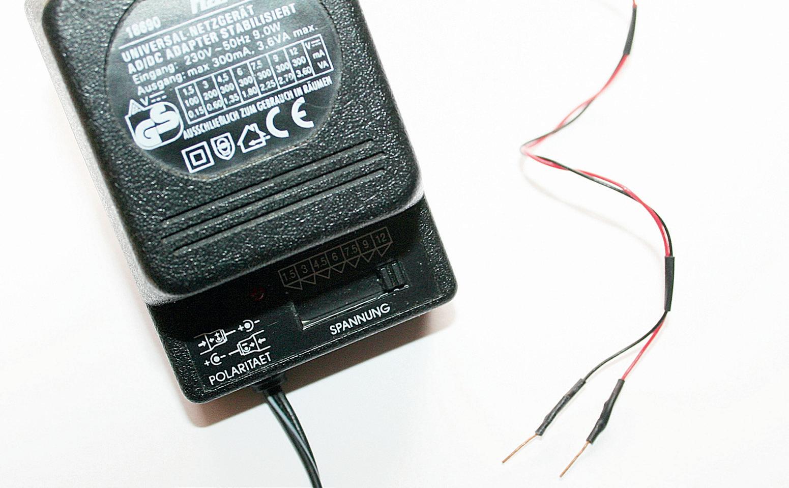
Figure 2.1: Plug-in power supply for first experiments, the connections must not touch each other when the supply is switched on
Practical assembly tip: A vacuum tube without a socket fitted with connecting leads cannot simply be plugged into a breadboard. This only works with an adapter board or a tube socket fitted with connecting wires. You can solder short leads onto a tube socket and fit them with short pins, which can then be inserted directly into the breadboard. This creates a simple adapter solution that allows the tube to be inserted or swapped out safely at any time. This is ideal for experimental setups without soldering.
A suitable tube socket for your tube, Noval for nine-pin tubes such as the ECC81, or a Pico7 socket for smaller seven-pin tubes, is available from electronics suppliers. Alternatively, you can use an old socket salvaged from a defective tube radio or other tube equipment. The result can look something like the figure below.
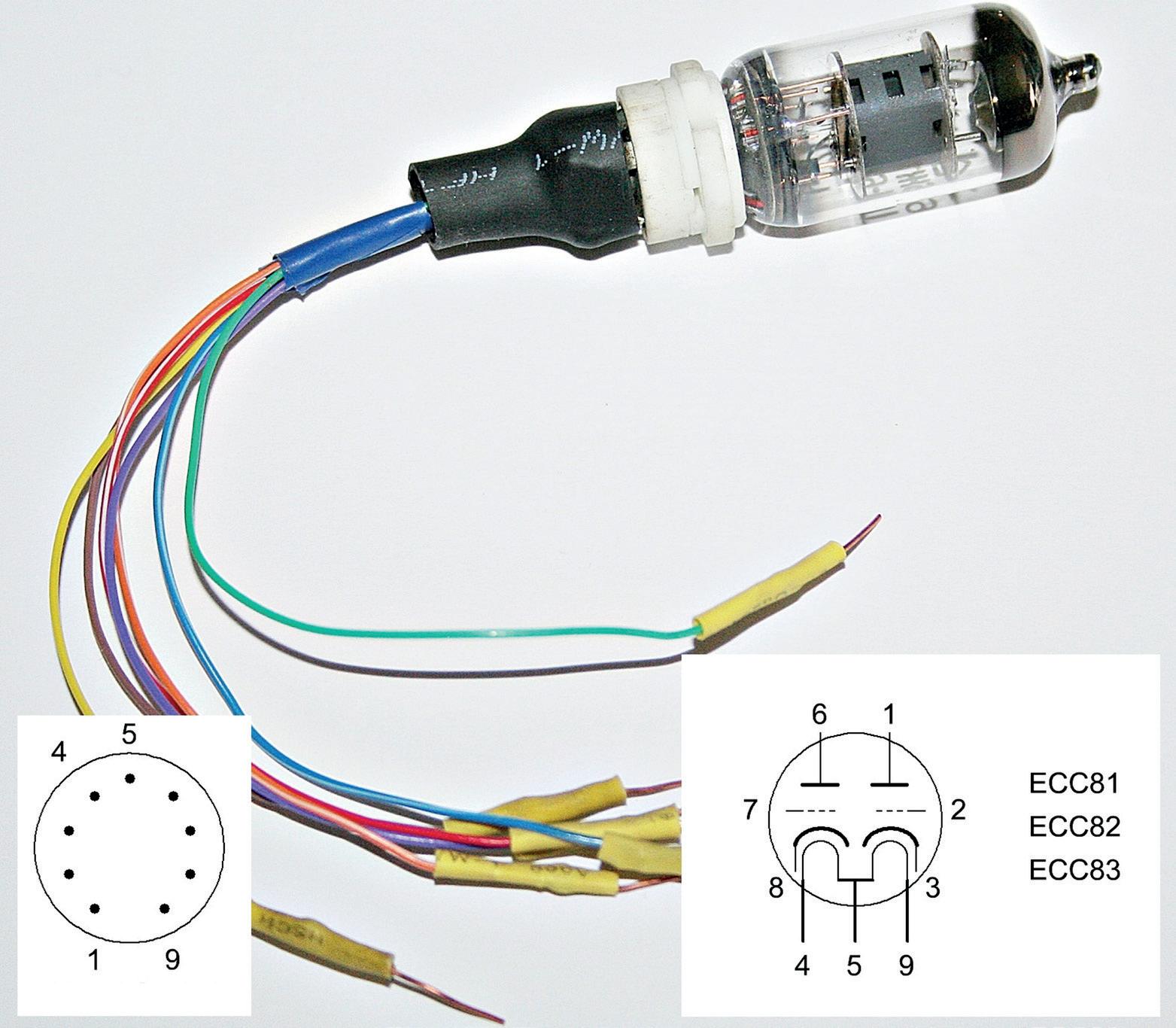
Figure 2.2: Tube socket with soldered connecting leads for the breadboard; below, the pin assignment of the ECC81/83
For tubes, the pin numbering is counted clockwise as viewed from the underside of the socket, starting with the first pin after the larger gap between two of the pins as shown in the figure. The heater pins 4 and 5 are also marked. At the bottom right you can see the schematic symbol for the ECC81/83 and the corresponding connections on the tube socket. This tube contains two triode systems that can be used independently of each other, which makes it an excellent choice for first experiments and measurements. More on this follows in the first circuits.
Please note:
• Avoid intermittent contacts, faulty operation, and incorrect readings.
• Do not attempt to insert the tube‘s pins directly into the breadboard. They are not sized to fit a standard breadboard, and bending them will cause them to break. The tube would be ruined at the latest when the glass envelope cracks.
• Always use the socket, preferably with connecting leads that are not too long (a few centimetres at most).
• Before switching on, check that all leads are correctly connected. This is especially important for the cathode heater. Pay particular attention to the heater voltage. More on this shortly.
Next, you will learn how to apply the heater voltage correctly in order to bring the cathode inside the tube up to its operating temperature.
Now things get interesting. In this step, you power up the heater of your vacuum tube and witness one of the most characteristic features of this technology: the soft, amber glow from inside the tube.
Unlike modern semiconductors, tubes require what is known as a cathode heater in order for electron flow to take place at all. This heater works in a similar way to the filament in an old incandescent light bulb, though with considerably less brightness and an entirely different purpose:
The heater inside the tube warms the cathode so that it can emit electrons. More on the topic of cathode heating can be found in a later chapter.
2.6.1
Many receiving tubes require a heater voltage of 6.3 volts, and this can be either AC or DC. It is applied between the two heater pins of the tube. On most nine-pin tubes, these are pins 4 and 5. However, the ECC81, ECC82, and ECC83 have a particular characteristic in this regard. These tubes require a heater voltage of twice the usual 6.3 volts. That is, 12.6 volts applied between pins 4 and 5. For 6.3-volt operation, pin 9 is also required: pins 4 and 5 are connected together, and 6.3 volts is then applied between this junction and pin 9. For our test setup, however, we will be using 12.6 volts applied directly to pins 4 and 5.
AC/DC sets (transformerless) 69, 72, 75, 76, 80, 82, 92, 199
AGC (Automatic Gain Control) 71, 196, 197, 200, 204, 207, 208, 209, 214, 215
Amplification factor (µ) 55, 56, 71, 86
Anode 28, 36, 37, 45, 46, 47, 48, 49, 50, 52, 53, 54, 55, 57, 58, 59, 61, 62, 65, 68, 74
Anode current 34, 35, 36, 37, 38, 39, 40, 41, 42, 43, 44, 48, 51, 53, 54, 55, 56, 57, 71
Anode voltage 27, 32, 35, 36, 37, 42, 44, 47, 51, 52, 53, 54, 55, 56, 57, 61, 71, 80, 92
Astable multivibrator 96, 97, 98, 100, 101, 102, 103
Autotransformer 80, 93, 94, 150, 175, 178, 183, 190
Battery tubes 67, 78, 164, 165
Bias 39, 40, 41, 54, 57, 106, 110, 117, 122, 128, 129, 130, 131, 137, 139, 148, 151
Bleeder resistor 150, 161, 162, 163
Breadboard 22, 25, 26, 27, 28, 29, 30, 32, 81, 91
C
Capacitor, coupling 43, 51, 52, 96, 97, 100, 101, 103, 104, 108, 109, 111, 114, 122, 125
Capacitor, electrolytic 50, 86, 92, 96, 97, 99, 110, 116, 122, 128, 129, 131, 132, 133, 134
Capacitor, paper/wax 203
Cathode 38, 40, 57, 78, 80, 83, 134, 145
Cathode follower 86, 87
Cathode ray tube (CRT) 19, 65, 89, 219, 225
Cathode resistor 39, 40, 41, 57, 86, 98, 99, 110, 111, 114, 122, 128, 129, 131, 139, 145
Characteristic curve 42, 43, 52, 53, 54, 55, 56, 57, 62, 110, 113, 121, 126, 220, 221, 237
Charge pump 168, 169
Class AB operation 142
Class A operation 121, 142
Class B operation 143
Common-anode circuit 84, 86, 87
Common-cathode circuit 84, 85, 86
Common-grid circuit 84, 86, 87
Contact cleaner 176, 188, 204, 208, 224, 231, 232
Crossover distortion 143
D
De Forest, Lee 47, 48
Dekal socket (B10) 66, 73, 88
Demodulation 196, 197, 199, 200, 214, 215
Diode (tube) 20, 34, 46, 47, 48, 49, 50, 51, 53, 57, 58, 59, 61, 63, 70, 76, 77, 115, 116
E
EABC80 72, 187, 196, 197, 199, 200, 201, 207, 208, 214
ECC81 25, 26, 27, 28, 29, 30, 31, 34, 35, 36, 38, 41, 43, 66, 69, 70, 71, 72, 73, 79, 82
ECC82 31, 66, 71, 81
ECC83 26, 27, 31, 53, 54, 55, 66, 71, 72, 75, 76, 77, 80, 82, 91, 101, 107, 112, 125, 128
ECC85 196, 197, 198, 201, 214
ECH81 73, 197, 198, 200, 201, 214
ECL86 82, 124, 129, 130, 131, 132
Edison Effect 46
Edison, Thomas 20, 45, 46
EF85 199, 214
EF86 66, 72, 73
EF89 71, 72, 73, 80, 196, 197, 199, 200, 201
EF95 66, 72, 113
EL84 66, 69, 71, 72, 75, 76, 77, 80, 81, 82, 124, 125, 127, 128, 130, 140, 147, 152, 157 EL95 66, 72, 124, 127, 128, 129
EM84 65, 66, 72, 73, 75, 77, 197, 199, 200, 215, 225
Emission (electron) 34, 38, 51, 78, 79, 83, 221
ESR (Equivalent Series Resistance) 133, 191, 202, 222, 226, 228, 231, 236
EZ80 154, 199, 214, 230
EZ81 154, 199, 230
F
Filament 31, 33, 45, 46, 49, 78, 79, 80, 83, 87, 91, 180, 183, 204, 230 Fleming, John Ambrose 46, 47
Flyback converter 170
Formierung 182, 202, 203
Frequency (intermediate) 63, 193, 195, 196, 197, 198, 199, 214
Getter 90, 220, 226, 230, 231, 235, 236
Grid 33, 34, 35, 36, 37, 38, 39, 40, 41, 42, 43, 44, 48, 51, 52, 53, 54, 55, 56, 57, 59, 61
Grid current 54
Grid voltage 33, 34, 35, 36, 37, 38, 39, 40, 41, 42, 43, 44, 51, 53, 54, 55, 56, 96, 106 GZ34 76, 77, 154, 230
H
Heater circuit 69, 79, 80, 81, 82, 90, 91, 151, 152, 180, 184, 186
Heater voltage 31, 32, 36, 37, 38, 47, 51, 59, 68, 69, 70, 72, 75, 76, 78, 79, 80, 81, 82
Heptode 63, 70
Hexode 62, 63, 70, 197, 198, 214
High voltage (safety) 22, 23, 24, 26, 59, 62, 68, 92, 120, 123, 140, 149, 152, 163, 164
Hum 117, 129, 131, 132, 133, 134, 136, 141, 148, 151, 156, 157, 158, 159, 164, 166
I
Impedance 85, 86, 87, 103, 108, 110, 113, 117, 119, 120, 121, 122, 123, 124, 125, 129
Indirect heating 80, 83
Isolation transformer 80, 94, 150, 151, 174, 176, 178, 182, 183, 184, 185, 189, 190
L
LC filter 156, 158, 159
Load resistor 42, 43, 139, 230
M
Magic eye 65, 70, 76, 199, 200, 201, 204, 208, 209, 225
Magnetron 65
Matched pairs (tubes) 226, 231
Multimeter 21, 22, 25, 27, 28, 33, 37, 38, 91, 180, 181, 182, 184, 210, 227, 229, 230
N
Negative feedback 110, 122, 131, 137, 145, 146, 147, 148, 215
New Old Stock (NOS) 90, 191, 217, 218, 226, 231
Noval socket (B9A) 25, 27, 66, 67, 72, 73, 76, 77, 88, 180
O
Octal socket (K8A) 66, 73
Ohm's Law 22
Operating point 40, 41, 42, 43, 52, 56, 57, 83, 111, 119, 121, 122, 125, 136, 148, 165
Oscilloscope 25, 65, 99, 102, 109, 116, 211, 219
Output transformer 113, 121, 122, 123, 124, 125, 129, 131, 136, 137, 139, 140, 141
Oxide cathode 83
P
Pentode 48, 62, 63, 69, 70, 71, 72, 76, 77, 82, 113, 114, 119, 121, 122, 126, 127, 128
Phase inverter 137, 143, 147
Pico-7 socket (B7G) 29, 66, 73, 127
Pi-filter 156
Plate contact (variable capacitor) 201, 208, 209, 224, 232
Potentiometer, logarithmic/linear 35, 37, 41, 99, 104, 106, 122, 125, 126, 127, 128, 130
Power supply 25, 26, 27, 29, 32, 33, 47, 50, 80, 81, 90, 91, 94, 111, 115, 116, 129, 131
Push-pull amplifier 136, 141, 142, 144, 145, 147
R
RC filter 132, 133, 148, 156, 157
Rectifier (selenium) 152, 154, 173, 199, 214, 220, 223, 224, 230, 232
Rectifier (tube) 47, 59, 70, 72, 152, 154, 156, 173, 199, 214
Rimlock socket (B8A) 66, 68, 73
Ripple 132, 133, 156, 157, 158, 159, 173, 203, 206
S
Safety 22, 23, 24, 26, 33, 80, 91, 92, 95, 116, 118, 131, 149, 150, 151, 161, 162, 163
Sag effect 154, 155
Screen grid 61, 62, 63, 65, 114, 122, 123, 126
Single-ended amplifier 121, 136, 137, 138, 141, 158, 159, 161
Socket types 65, 66, 67, 73, 88, 220
Space charge 49, 51
Superhet 63, 192, 193, 195, 196, 199, 215
Suppressor grid 62, 63, 65, 126
T
Tetrode 48, 61, 62, 70
Thermionic emission 38, 46, 47
Tone control 22, 189, 204, 214, 215
Transconductance (gm) 226
Transformer, mains 28, 41, 69, 80, 81, 92, 93, 123, 124, 129, 131, 150, 151, 152, 153
Triode 25, 27, 30, 33, 34, 35, 37, 38, 47, 48, 49, 50, 51, 53, 57, 59, 61, 63, 64, 66, 70
Tube socket 25, 26, 27, 29, 30, 66, 67, 91, 180, 235
Tube tester 188, 211, 227, 230, 236
V
Variable capacitor 201, 208, 224, 232
VFD (Vacuum Fluorescent Display) 65
Voltage doubler 114, 115, 116
W
Warm-up time 78, 79, 154
Wiring (internal) 26, 80, 84, 91, 124, 132, 134, 166, 176, 177, 204, 205, 215, 236
Vacuum tubes continue to exert a special fascination. Their long-lasting operation, robustness, and characteristic behavior fundamentally distinguish them from modern semiconductor technology. Despite their age, tubes are by no means merely historical components; they are still used today in audio technology, measurement technology, and especially in hobbyist applications.
This book is aimed at electronics enthusiasts and hobbyists who want to not only learn about and understand vacuum tubes in theory, but also use them in practice. It conveys the fundamentals of tube technology, explains the di erent designs and designations, shows typical circuits, and addresses power supplies, measurements, and safety-related aspects.
The focus is on practical explanations and realistic examples from the workshop. Numerous tips help you avoid typical mistakes, build circuits, and understand tube devices and their construction. Basic knowledge of electronics is assumed.
Vacuum Tubes: A Practical Guide to Tube Electronics o ers an accessible and thorough introduction to tube technology – factual, comprehensible, and with a clear focus on practical applications.

Gerd Weichhaus has been working with classic electronics and tube technology for many years. His focus is on the practical understanding of electronic circuits as well as the repair and analysis of vintage radio, audio, and tube equipment. He is the author of several books on electronics and runs several websites on the subject, including bandmaschinenseite.de, bastelnmitelektronik.de, and gerdweichhaus.de, where he shares his knowledge in a practical and understandable way. In his publications, he combines sound fundamental knowledge with practical experience and places particular emphasis on the safe and comprehensible handling of vintage technology.
Elektor International Media www.elektor.com