Object-Oriented PLC Programming in CODESYS
Modular and Scalable Control Systems
Using
Structured Text

Pro

Using

Pro
●
Majid Pakdel
● This is an Elektor Publication. Elektor is the media brand of Elektor International Media B.V.
PO Box 11, NL-6114-ZG Susteren, The Netherlands
Phone: +31 46 4389444
● All rights reserved. No part of this book may be reproduced in any material form, including photocopying, or storing in any medium by electronic means and whether or not transiently or incidentally to some other use of this publication, without the written permission of the copyright holder except in accordance with the provisions of the Copyright Designs and Patents Act 1988 or under the terms of a licence issued by the Copyright Licencing Agency Ltd., 90 Tottenham Court Road, London, England W1P 9HE. Applications for the copyright holder's permission to reproduce any part of the publication should be addressed to the publishers.
● Declaration
The authors and publisher have used their best efforts in ensuring the correctness of the information contained in this book. They do not assume, or hereby disclaim, any liability to any party for any loss or damage caused by errors or omissions in this book, whether such errors or omissions result from negligence, accident or any other cause.
● British Library Cataloguing in Publication Data
A catalogue record for this book is available from the British Library
● ISBN 978-3-89576-696-1 Print ISBN 978-3-89576-697-8 eBook
● © Copyright 2024 Elektor International Media www.elektor.com
Editor: Glaucileine Vieira
Prepress Production: Elektor Printers: Ipskamp, Enschede, The Netherlands
Elektor is the world's leading source of essential technical information and electronics products for pro engineers, electronics designers, and the companies seeking to engage them. Each day, our international team develops and delivers high-quality content - via a variety of media channels (including magazines, video, digital media, and social media) in several languages - relating to electronics design and DIY electronics. www.elektormagazine.com
The industrial automation landscape is rapidly evolving, demanding more flexible, modular, and maintainable solutions than ever before. As control systems grow in complexity, the traditional approaches to PLC programming—centered around procedural logic and ladder diagrams—begin to show their limitations. This has opened the door to more advanced paradigms, particularly Object-Oriented Programming (OOP), which has long been the standard in mainstream software development.
This book is a practical guide for engineers, programmers, and students seeking to harness the power of OOP in the context of industrial automation using PLCs. The content is focused on the CODESYS development environment and Structured Text (ST), both of which support modern programming techniques while maintaining compatibility with real-time automation requirements. It is based on my personal study notes taken during the Udemy course PLC Object Oriented Programming: Advanced Infrastructure.
This book is my attempt to organize the core principles, demos, and practical techniques into a structured, reference-friendly format. Chapter 1 begins with an introduction to OOP within the PLC domain and an overview of the CODESYS software platform. Chapter 2 covers the foundational elements of Structured Text, including control structures, arrays, loops, and state machines. These are essential before delving into object-oriented concepts.
From Chapter 3 onward, readers are introduced to the building blocks of OOP in PLCs: classes, methods, properties, inheritance, and polymorphism. Each chapter includes realworld examples and demos designed to reinforce learning through practice. Later chapters introduce more advanced topics, such as access control, abstraction via interfaces, delegation, and the implementation of flexible finite state machines using object-oriented design patterns.
Whether you’re an automation professional transitioning to modern programming methodologies or a student aiming to Build a solid foundation in control system software architecture, this book offers a hands-on, application-focused approach to mastering object-oriented programming in PLCs. It is my hope that these notes-turned-book will serve you as both a learning tool and a long-term reference, helping you design cleaner, smarter, and more scalable control systems.
In this book, we explore a range of advanced programming concepts that have recently been introduced into the realm of PLC (Programmable Logic Controller) programming. These concepts, long established in higher-level programming languages such as Java, C++, C#, and Python, are now becoming available in PLC development environments. Concepts such as classes, methods, properties, inheritance, access specifiers, polymorphism, interfaces, delegation, composition, wrappers, and modular features are no longer exclusive to general-purpose software development. They are now accessible to automation engineers working with PLCs.
This book is the first structured guide to cover all of these object-oriented programming (OOP) principles in the context of PLC programming, complete with detailed explanations and real-world examples. These capabilities have been progressively introduced through recent expansions of the IEC 61131-3 standard over the past two to three years. We believe this marks the next step in PLC software development.
Although the adoption of these concepts is still in its early stages and not yet widespread, major PLC vendors have already begun transitioning toward this approach. You might ask: Why are these concepts important? The answer lies in the long-term benefits they offer. These methodologies allow you to design scalable, modular, and maintainable PLC software architectures.
With object-oriented programming, your PLC applications become extensible. You can add new functionality without altering the core logic of your program. This is a major advantage in industrial automation, where updates and modifications are frequent and often time-sensitive. If you’ve ever revisited a project after a month or two to implement a seemingly minor change, you’ll understand how inflexible and cumbersome traditional PLC programming methods can be.
By adopting OOP principles, you can Build reusable projects templates that serve as foundations for future applications. In this book, we will discuss how to establish a hierarchical project structure and introduce layered design patterns. These patterns isolate functionality so that modifying one layer (e.g., hardware interaction or UI logic) doesn’t require changes across the entire project. This design approach makes development and maintenance more manageable.
It’s important to clarify that object-oriented programming will not necessarily make initial development faster. In fact, designing a robust software infrastructure requires a significant upfront investment of time and thought. However, once this infrastructure is in place, future changes, upgrades, and feature additions become remarkably efficient and straightforward.
Consider a practical example: you’ve deployed a control system for a production line, and the client later decides to expand it (e.g., by adding a new conveyor, a dosing machine, or an additional motor, as illustrated in Figure 1.1). With traditional programming methods, this would require significant rewrites. With OOP, however, integrating new devices becomes a matter of modifying a small portion of code, simply instantiating and configuring new object types like motors, VFDs, valves, silos, or load cells.
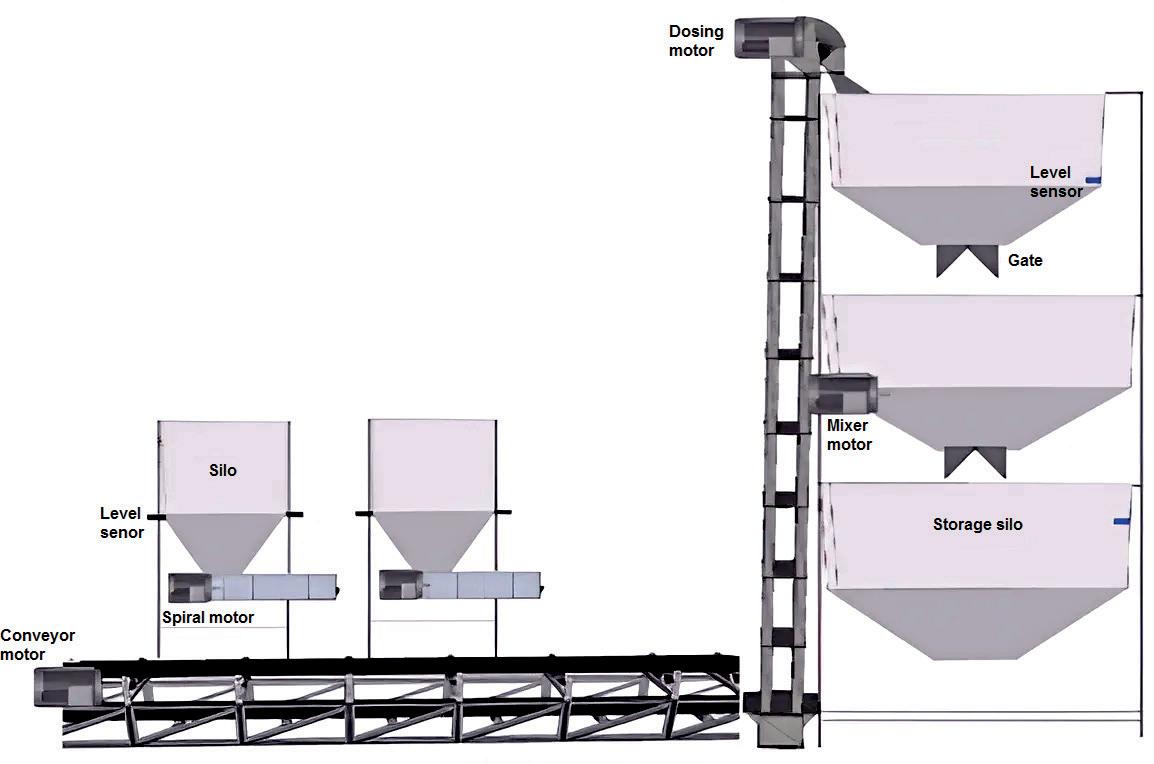
This book will guide you through building such an object-oriented infrastructure. By the end, you will have a collection of reusable, modular software components that you can easily adapt for any future project.
In the final section of the book, we will focus on developing a complete template project, a blueprint you can reuse and customize for most of your upcoming PLC automation solutions.
In this section, we will guide you through downloading and installing the software required to begin programming PLCs. The platform we will use is CODESYS, a widely adopted development environment for industrial automation.
CODESYS is a powerful and adaptable software solution used by many leading PLC manufacturers such as WAGO, Schneider Electric, and others. In fact, the programming
environments provided by these manufacturers are often based entirely on the CODESYS platform. Therefore, by learning how to work with CODESYS, you gain transferable skills applicable to multiple PLC brands simultaneously.
One of the key advantages of CODESYS is that it is completely free for learning and development purposes. No license is required to install or use the software in simulation mode. It supports all six IEC 61131-3 programming languages, making it an ideal tool for practicing complex automation scenarios and enhancing your programming skills.
However, there’s one important limitation to be aware of: the free version does not support direct communication with a physical PLC. You can simulate logic, visualize HMIs, and test algorithms within the software, but in order to deploy code to real hardware, a licensed version is required. Some CODESYS-based platforms may offer 30-day trial licenses, and we will explain how to access and use these in later chapters, especially if you’re working on a real-world project.
To get started, follow these steps:
1. Visit the official CODESYS website: Go to www.codesys.com or search for “CODESYS V3.5 SP20 download” using your preferred search engine.
2. Create a CODESYS account: Register by filling out the sign-up form. After submitting, a confirmation email will be sent to your inbox. Click the activation link in the email to finalize your registration.
3. Log in and download the installer: Once your account is activated, log in to the CODESYS website and find the download page for CODESYS V3.5 SP20 (or a newer version, if available). Select the version compatible with your operating system.
4. Download and install: The installer is approximately 1.5 GB in size. After downloading, launch the setup file and follow the on-screen instructions to complete the installation process.
Once the installation is complete, you will be ready to Start learning how to program PLCs. In the following chapters, we will cover the fundamentals of PLC programming using CODESYS, and gradually move on to more advanced concepts and real-world applications.
Language
2.1
In this section, we will provide a brief overview of how to create a Structured Text (ST) project in CODESYS. This will be a simple, introductory walkthrough to help you get started.
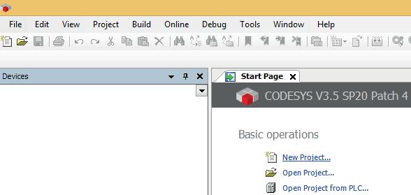
Once you launch CODESYS, the Start page will appear. From there, click on the New Project... option, as illustrated in Figure 2.1.
In the New Project window, type if_statement as the project name and click OK, as shown in Figure 2.2.
Chapter 2 • The Structured Text (ST) Programming Language

Figure 2.2: Naming the project “if_statement” in the New Project window
In the Standard Project window, select the device as “CODESYS Control Win V3 x64” and set the programming language for PLC_PRG to “Structured Text (ST)”. Then, click OK, as illustrated in Figure 2.3.
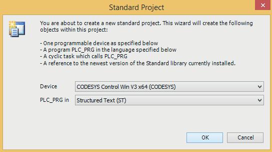
Figure 2.3: Settings of the Standard Project window
The project is now ready. To open the programming interface, double-click on PLC_PRG (PRG). This will open the programming window, as shown in Figure 2.4.
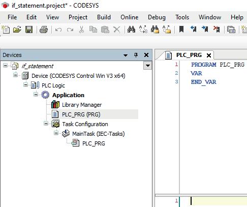
Figure 2.4: Double clicking on PLC_PRG (PRG).
Let’s Start with a simple example: controlling a motor by turning it on and off. This basic scenario is intended to demonstrate the syntax of Structured Text (ST). First, define the program variables, as shown in Figure 2.5.
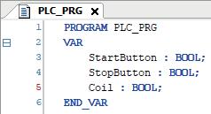
Figure 2.5: Defining the program variables
Chapter 2 • The Structured Text (ST) Programming Language
Next, enter the code in the programming (PRG) window, as shown in Figure 2.6.

Figure 2.6: Code in the programming (PRG) window
Now, navigate to the Online menu and ensure that the simulation mode is active, as shown in Figure 2.7.

Figure 2.7: Selecting Simulation from the Online menu
Next, click on the Login icon (or Alt+F8) to open the CODESYS Login window. Click Yes to proceed, as shown in Figure 2.8 and Figure 2.9, respectively. We are now in simulation mode. Next, click on the Start icon (or F5), as illustrated in Figure 2.10.
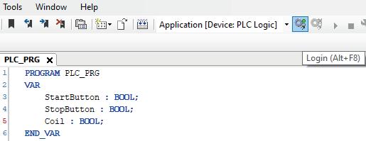
2.8: Clicking on the Login icon (or Alt+F8)

Figure 2.9: Clicking on the Yes button

Figure 2.10: Clicking on the Start icon (or F5)
Now that we are in run mode, enter values in the Prepared Value column. Set the StartButton to TRUE. To execute the program, press Ctrl+F7, as shown in Figure 2.11.

Figure 2.11: Executing the program by pressing Ctrl+F7
As shown in Figure 2.11, the coil is now activated. To deactivate the StartButton, set its value to FALSE in the Prepared Value column and press Ctrl+F7, as shown in Figure 2.12.

Figure 2.12: Executing the program by pressing Ctrl+F7
As shown in Figure 2.12, the coil remains active (TRUE) and is running. To activate the StopButton, set its value to TRUE in the Prepared Value column and press Ctrl+F7 to execute the program, as illustrated in Figure 2.13.

Figure 2.13: Executing the program by pressing Ctrl+F7
As shown in Figure 2.13, the coil is now deactivated. To deactivate all components, set the StopButton value to FALSE in the Prepared Value column and press Ctrl+F7, as illustrated in Figure 2.14.

Figure 2.14: Executing the program by pressing Ctrl+F7
This section covered the use of the if statement. In the next sections, we will continue exploring other fundamental concepts in Structured Text (ST).
In this section, we will learn how to use standard function blocks such as timers, counters, rising edge triggers, falling edge triggers, and related elements. To demonstrate these concepts, we will create a simple application involving a Start button, a Stop button, Motor 1, and Motor 2.
The functionality will be as follows: when the Start button is pressed, Motor 1 is activated immediately, followed by Motor 2 after a defined delay, demonstrating a basic form of sequential activation. We begin by defining the necessary variables, as shown in Figure 2.15.
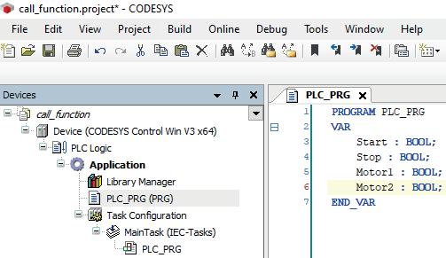
Figure 2.15: Defining the program variables
Chapter 2 • The Structured Text (ST) Programming Language
We also need to add a timer. To do this, right-click in the program window and select the Input Assistant... option, as illustrated in Figure 2.16.
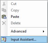
Figure 2.16: Selecting the Input Assistant… option
Navigate to Function Blocks, then expand the Standard Timer category. Select TON (Timer On-Delay) and click OK, as shown in Figure 2.17.
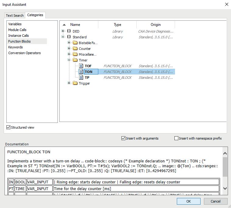
Figure 2.17: Selecting the TON timer
Define Timer1 as an instance of the TON function block. Then, click Done and select.
Declare Variable to open the Auto Declare window, as shown in Figure 2.18 and Figure 2.19, respectively.
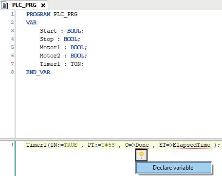
Figure 2.18: Selecting Declare Variable for Done

Figure 2.19: The Auto Declare window for Done
Now, click OK in the Auto Declare window, as shown in Figure 2.19. Follow a similar procedure to declare the variable ElapsedTime, as shown in Figure 2.18, and confirm by clicking OK in the Auto Declare window, as illustrated in Figure 2.20.
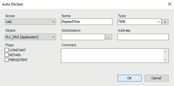
2.20: Auto Declare window for ElapsedTime
This completes the process of creating and configuring the timer, as shown in Figure 2.21.
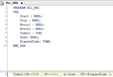
Figure 2.21: Creating the timer
An alternative approach is to manually create a timer instance, such as Timer2. In this case, you only need to specify the parameters relevant to your application, as demonstrated in Figure 2.22.
Next, we return to our application. For this example, we will delete Timer2 and proceed with writing the application code, as illustrated in Figure 2.23.
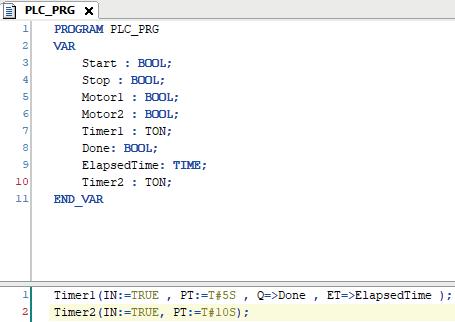
Figure 2.22: Manually creating the timer
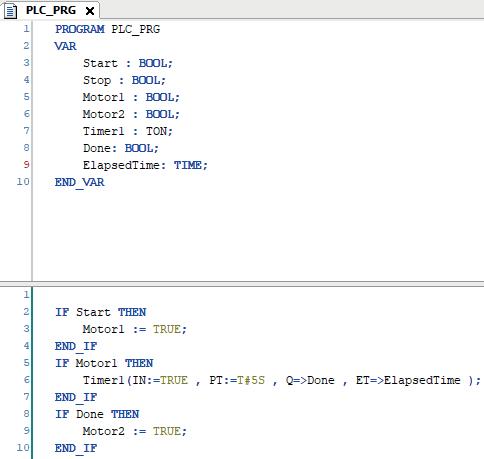
Figure 2.23: Writing the application code
The code shown in Figure 2.23 can also be written in an alternative form, as shown in Figure 2.24.
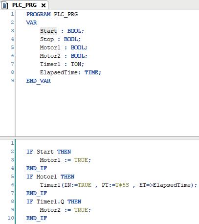
Figure 2.24: Writing the code from Figure 2.23 in an alternative way
Once the timer has elapsed, it is essential to reset it before reuse. This step is critical for ensuring proper timer functionality. To reset the timer, use the following instruction: Timer1(IN := FALSE);.
If the timer is not reset and the Stop button is pressed, the timer will remain in a saturated state. As a result, when the program returns to the timer, the output (Q) will remain TRUE, since the timer was never reset. Therefore, after detecting that the timer has elapsed, include a reset command if the timer is to be reused. We now add the code for the Stop button, as shown in Figure 2.25.
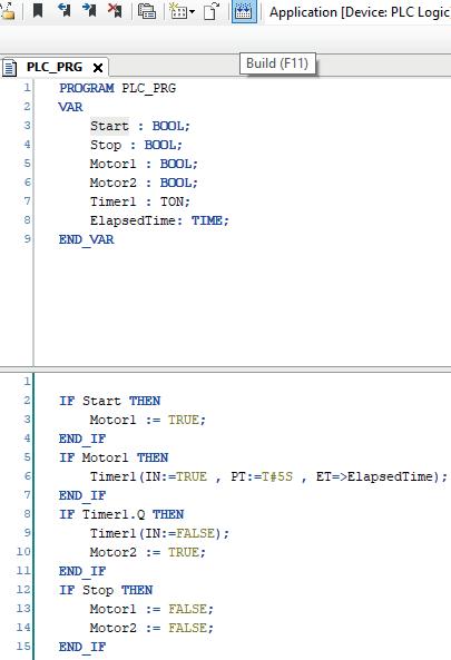
Figure 2.25: Code for our application
To compile the application code, click the Build icon (or F11), as demonstrated in Figure 2.25. The project should compile successfully without any errors. Next, navigate to the Online menu and ensure that Simulation Mode is active. Then, click the Login icon (or Alt+F8).
Once logged in, Start the application by clicking the Start icon (or F5) in the simulation window. At this point, observe the behavior of Motor1 and Motor2. If desired, you can monitor these variables in real time by adding them to the Watch window. To do this, drag and drop Motor1 and Motor2 into the Watch window, as illustrated in Figure 2.26.
Now, assume that the Start button is pressed by setting its value to TRUE in the Prepared Value column, and then execute the program by pressing Ctrl+F7, as shown in Figure 2.27.
Chapter 2 • The Structured Text (ST) Programming Language
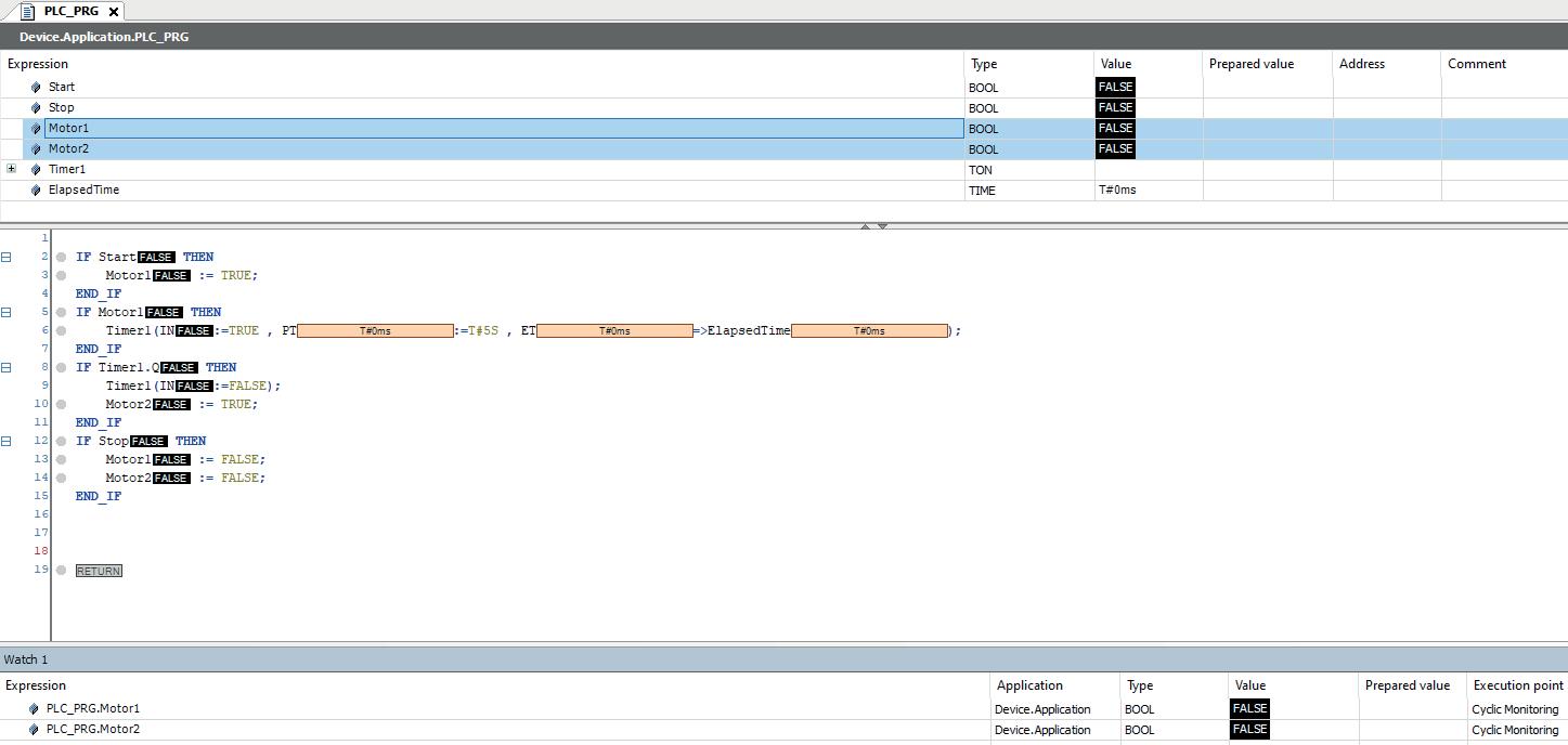
2.26: Dragging motor1 and motor2 into the Watch window
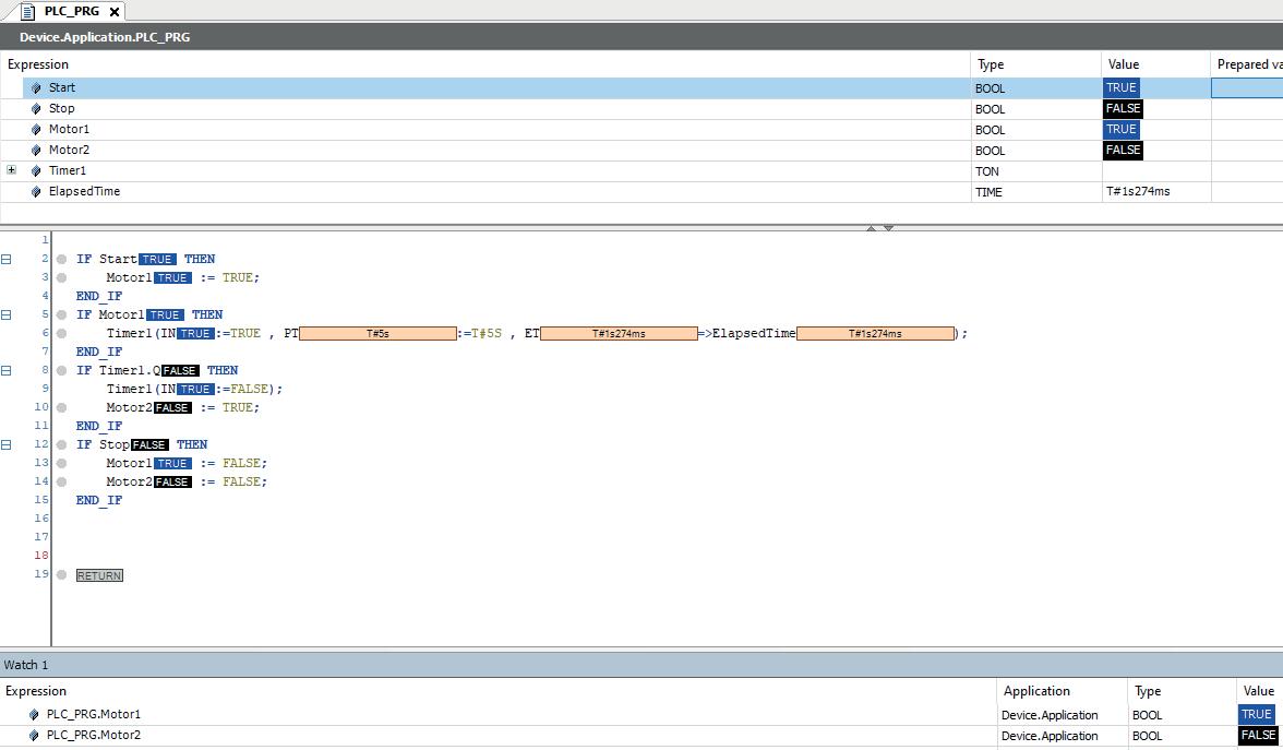
2.27: Executing the program
After executing the program, the timer resets itself every 5 seconds. The most efficient way to structure such a program is by using a finite state machine, which will be discussed in the next section. Now, if the Stop button is activated, both motors will be turned off, as depicted in Figure 2.28.

A more efficient approach to resetting the timer is to do so only when the Stop button is pressed. This prevents the timer from continuously counting over. The purpose of resetting the timer when the Stop button is pressed is to allow the process to be reinitiated from a clean state. Once the timer is reset, Motor1 will run, and the timer will begin counting towards the preset duration. After the timer completes, Motor2 will then be activated. This is why it is essential to reset the timer, and we have modified the program accordingly, as shown in Figure 2.29.
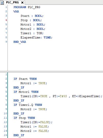
Figure 2.29: The modified program for our application
Next, compile the application code by clicking the Build icon (or F11), ensuring that it compiles successfully without any errors. Then, navigate to the Online menu, confirm that simulation mode is active, and click the Login icon (or Alt+F8). Once logged in, click the Start icon in the simulation window (or F5) to execute the application.
Assuming the Start button is set to TRUE in the Prepared Value column and the program is executed by pressing Ctrl+F7, the timer does not reset automatically. To reset the timer, deactivate the Start button and activate the Stop button. Upon pressing Start again, the timer begins counting once more.
In Structured Text (ST), when working with buttons, it is recommended to use triggers. Triggers respond only to the rising edge of the button press, meaning that even if the button is toggled, only the moment of the press is evaluated, and it is not continuously evaluated. Triggers should always be defined at the top of the Structured Text (ST) program. To implement this, right-click on the program window and select the Input
Assistant… option, as demonstrated in Figure 2.16.
Next, navigate to Function Blocks, then select Standard Trigger, and choose R_TRIG. Finally, click the OK button, as shown in Figure 2.30.

Figure 2.30: Selecting the R_TRIG option
In the program, we define two rising edge triggers: StartTrigger and StopTrigger. As seen in the syntax, each trigger has a clock and an output. The output will be accessed in the same manner as the timer output, allowing us to delete the previous implementation. When the Start button is pressed, the output (Q) is activated for a very brief moment, effectively generating a pulse. This pulse indicates that the Start button was pressed and will automatically deactivate shortly thereafter. The same behavior occurs with the Stop button: when pressed, only a pulse from the Stop activation is generated, and the output (Q) of that function will turn off again. We have modified the application program accordingly, as shown in Figure 2.31.
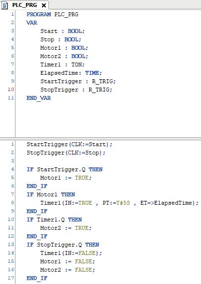
Figure 2.31: Modified program for the application
First, compile the application code by clicking the Build icon (or F11), ensuring it compiles successfully without any errors. Next, navigate to the Online menu and confirm that Simulation Mode is active. Then, click the Login icon (or Alt+F8). After logging in, press the Start icon (or F5) in the simulation window to execute the application.
Press the Start button by setting its value to TRUE in the Prepared Value column, then execute the program by pressing Ctrl+F7. Next, set the value of the Stop button to TRUE in the Prepared Value column and press Ctrl+F7 to run the program. At this point, both Motor1 and Motor2 will be turned off.
If the Stop value is set to FALSE in the Prepared Value column and Ctrl+F7 is pressed to execute the program, we will observe that even though the Start button remains active, the program does not run. This occurs because the program is waiting for a pulse from the Start button, specifically the transition from 0 to 1, as shown in Figure 2.32.

Figure 2.32: The Program does not run even though the Start in on
To run the program, first set the Start value to FALSE in the Prepared Value column and press Ctrl + F7. Then, set the Start value to TRUE and press Ctrl + F7 again. After five seconds, both motors will be activated. To Stop the program, set the Stop value to TRUE in the Prepared Value column and press Ctrl + F7. Both motors will then be turned off.
This section served as an introduction to Structured Text (ST), preparing us to Start Object-Oriented Programming (OOP). If you are unfamiliar with these concepts or the associated syntax, transitioning to OOP can be challenging. Therefore, ensure that you are comfortable with these foundational concepts before proceeding to Object-Oriented Programming (OOP).
This section introduces the CASE statement. The CASE statement functions similarly to an IF statement but offers a more structured approach, especially when dealing with a sequence of steps in a process. For example, consider a system with a mixer and a pump, where a solid product is inside the mixer. The process consists of several steps: first, the product is mixed; then liquid is added through the pump; the pump is stopped; mixing continues; and the cycle of adding liquid and stopping the pump repeats. Finally, the gate of the mixer is opened to make the product ready.
As this example shows, the process involves multiple steps. The most effective way to design such a sequence is by using a finite state machine (FSM). There are various ways to implement an FSM, and one of the simplest methods is by using the CASE statement. The program code for this process is as follows.
A
abstraction, 8-9, 152-153, 202-203, 218219, 224-225, 228-229 actuator, 222-223 address, 64-65, 78-79, 118-119, 126-127, 130-131, 138-139, 190-191, 252-257, 260-261, 270-271, 276-277 alarm, 178-179 algorithmic, 90-91, 94-97, 106-109 analog, 34-39, 44-45, 160-161, 172-179, 204-205, 208-209, 218-221, 228-233, 238-241, 244-247 analyzer, 244-245 angle, 220-221 arc, 118-119 array, 4-5, 36-37, 44-47, 52-53, 74-75, 80-81, 116-117, 134-135, 138-139, 148-149, 200-203, 214-217, 270-273, 278-281, 286 attribute, 152-153 automation, 8-11, 182-183, 218-219
B backbone, 252-253 batch, 244-245 behavioral, 250-251 block, 18-19, 40-43, 56-61, 68-69, 72-73, 80-83, 90-93, 108-111, 122-123, 154155, 206-207, 240-241, 246-247, 256257, 260-261, 278-279 BOOL, 30-31, 42-43, 110-111, 154-155, 208-209
box, 4-5, 34-35, 38-39, 42-43 buffering, 198-199 button, 16-19, 22-29, 32-35, 44-45, 5253, 56-57, 78-81, 86-95, 106-107, 120123, 136-137, 142-143, 154-155, 160161, 202-203, 208-209, 246-247 bypass, 188-189, 256-257
C cell, 244-249 chain, 116-117, 182-183, 224-225
child, 190-191 class, 4-5, 56-105, 108-149, 152-209, 212-233, 236-279
clock, 28-29
CODESYS, 4-5, 8-15, 34-35, 38-39, 4243, 50-51, 56-59, 62-63, 66-67, 92-93, 110-111, 154-155, 214-215, 220-221, 252-255, 260-263 communication, 10-11, 274-275 compiler, 252-255, 274-275 condition, 38-39, 42-43, 48-49, 52-53, 62-63, 78-81, 86-87, 90-91, 96-97, 106-107, 120-121, 130-133, 138-141, 152-153, 206-207, 244-245, 272-273, 276-279, 282-285 constructor, 6-7, 260-261 contactor, 64-65, 246-247 controller, 8-9, 40-41, 78-79, 106-107, 218-219, 270-271 conveyor, 10-11, 122-127, 200-201 counter, 138-139, 214-217 cycle, 30-31, 80-81, 138-139, 180-181, 244-245, 282-283, 286
D
decouple, 270-271, 274-275 decrease, 210-211 degree, 166-167, 180-181, 218-221 deploy, 10-11 depth, 186-187, 220-221 detect, 80-81, 246-247 diagram, 58-61, 256-257 display, 64-65, 244-245 divide, 88-89
E embedded, 40-41, 128-129 encapsulated, 116-117, 134-135, 186187, 278-279 evolving, 8-9
F
fault, 48-49, 78-81, 86-87, 90-91, 96-97, 100-101, 108-109, 112-113, 120-121, 130-133, 136-141, 158-161, 168-169,
228-229, 246-247 feedback, 48-51, 64-65, 78-79, 138-139, 212-213, 218-221
G
gain, 10-11, 90-91, 170-171, 228-229, 240-241, 256-257, 270-271 group, 66-69
H
halt, 32-33, 78-81, 140-141 hardcoded, 206-207, 256-257 hardwired, 234-235, 256-257 hierarchical, 8-9, 224-225 humidity, 200-201 hypothetical, 248-249
I
ideal, 10-11, 222-223, 228-231, 272-273 idle, 210-211 inactive, 52-53, 112-113, 190-191, 216217
increase, 50-51, 286 industry, 90-91, 200-201 inrush, 78-79 interdependent, 106-107 international, 4-5 intervention, 80-81 intuitive, 154-155, 228-229 invalid, 280-281 IO, 6-7, 92-93, 160-161, 174-175
L ladder, 8-9, 56-61 library, 4-5, 212-213 linear, 224-225 loss, 4-5 M machinery, 78-79 maintenance, 8-9, 270-271 map, 134-137, 144-145, 160-161, 164165, 216-217 material, 4-5, 204-205 measurement, 206-207, 244-245 memory, 252-255, 262-263 message, 176-177
mimics, 230-231 model, 224-225 module, 244-245 multilevel, 180-181
N negligence, 4-5 nested, 224-225
O
offload, 254-255 OOP, 8-11, 30-31, 38-39, 56-57, 108-109, 166-167, 202-203, 248-249
P
pattern, 206-207, 224-225, 250-251, 260261, 272-273, 278-279 period, 284-285 phase, 166-167, 280-281 piece, 250-251 pipe, 52-53, 218-219 piston, 252-253, 270-271 polymorphic, 190-191, 218-219 prerequisite, 186-187 priority, 80-81, 102-103 proximity, 114-115 pulse, 28-29, 206-207, 228-229 puzzle, 224-225, 250-251
Q
quality, 4-5 question, 108-109, 198-199
R
realm, 8-9 rearranging, 270-271 recall, 116-117, 136-137, 236-237 redefine, 170-171, 196-197 redundancy, 38-39, 56-59, 182-183, 238239 relay, 34-35, 38-41, 160-161, 246-247 reliability, 200-201 reservoir, 48-49, 54-55 ripple, 224-225 risk, 88-91, 224-225
S sampling, 244-247 sequential, 18-19, 78-81, 136-137 serial, 134-135 signaling, 276-277 solenoid, 218-221 solid, 8-9, 30-31, 76-77, 200-201 space, 252-253, 262-263 spiral, 200-201 ST, 4-5, 8-9, 12-55, 58-61, 110-111, 122123, 154-155, 222-223, 230-233 summary, 134-137, 224-225 symbol, 222-223, 254-255
T
tabular, 36-37, 44-45, 52-53, 178-179, 194-195 team, 4-5 technical, 4-5 template, 10-11 theory, 272-273 toggle, 208-209 toward, 8-9, 154-155, 254-257 track, 208-209, 272-273 trial, 10-11, 228-229 trigger, 28-29, 32-33, 80-81, 106-107, 176-177, 180-181 trip, 78-79
U uniform, 222-223 uninitialized, 278-279 unpredictable, 94-95, 224-225 update, 126-127, 144-149, 152-153, 270273 usage, 174-175, 210-211
V valid, 38-39, 80-81, 210-211, 220-221, 280-281 vector, 116-117, 134-135 video, 4-5 voltage, 176-177, 236-241, 244-245
W
WAGO, 10-11 warning, 176-177, 180-181, 244-245 website, 10-11 widespread, 8-9, 218-219 wiring, 256-257 wrong, 136-137
Y years, 8-9
Z zero, 80-81, 192-193, 200-201, 206-207, 278-281
Object-Oriented PLC Programming in CODESYS offers a structured and practical approach to modern PLC development using object-oriented principles. It is a guide for engineers, programmers, and students seeking to harness the power of object-oriented programming (OOP) in the context of industrial automation with PLCs.
The content focuses on the CODESYS development environment and Structured Text (ST), both of which support modern programming techniques while maintaining compatibility with real-time automation requirements. Through step-by-step demos and instructional examples, it demonstrates how modular, reusable code can enhance development efficiency, simplify ongoing maintenance, and enable scalable and flexible control system architectures.
Key topics include:
> Structured Text fundamentals: conditions, loops, arrays, and functions
> Object-oriented concepts: classes, methods, and inheritance
> Advanced techniques: polymorphism, interfaces, and access control
> Modular design with reusable components and structured program flow
> Implementation of finite state machines and scalable application design
Built around instructional demos and clear explanations, this book helps readers develop maintainable and modern control software in the CODESYS environment using proven programming techniques.

Dr. Majid Pakdel earned his bachelor’s degree in electrical-telecommunications engineering from Amirkabir University of Technology, Tehran, in 2004. He completed a master’s degree in electrical power engineering at Isfahan University of Technology in 2007, and a Ph.D. in the same field from the University of Zanjan in 2018. During his Ph.D. studies, between 2015 and 2016, he was a visiting student at the Department of Energy Technology at Aalborg University. In 2023, he obtained a second master’s degree in computer engineering, specializing in artificial intelligence and robotics, from Malek Ashtar University of Technology, Tehran.
Dr. Pakdel has authored more than 20 research papers and 10 technical books in electrical engineering and computer science.
Elektor International Media www.elektor.com