Race, Education, and Reintegrating Formerly Incarcerated Citizens: Counterstories and Counterspaces (Critical Perspectives on Race, Crime, and Justice) (Ebook PDF)
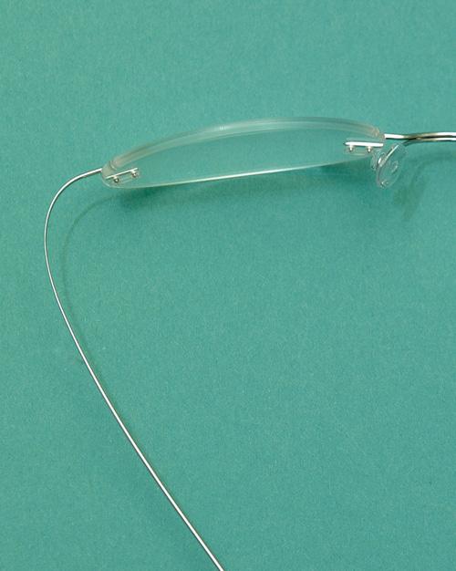
1-5. A nylon cord frame or “string mount” holds the lens in place with a cord that fits around the edge of the grooved lens.
frames.
Figure
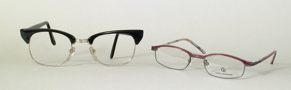
Figure 1-6. Examples of combination
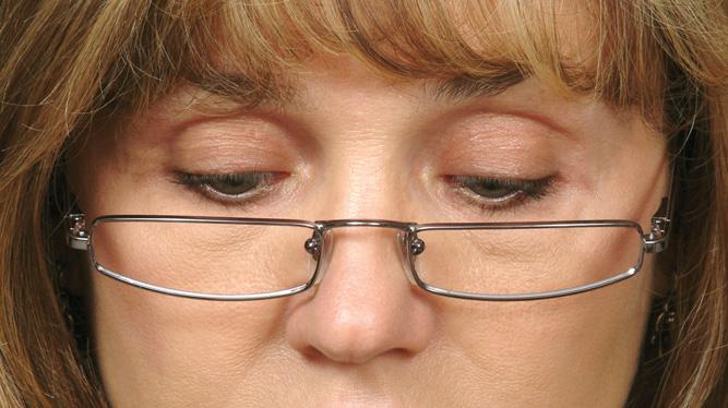
Figure 1-7. Half-eye frames in use. Half-eyes are made especially for those who need a reading correction but no correction for distance vision.
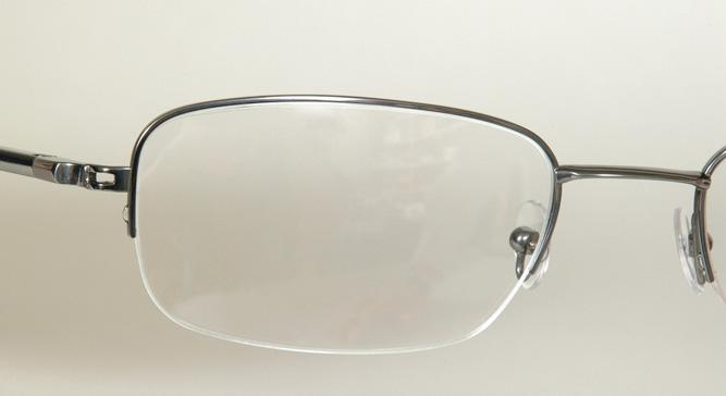
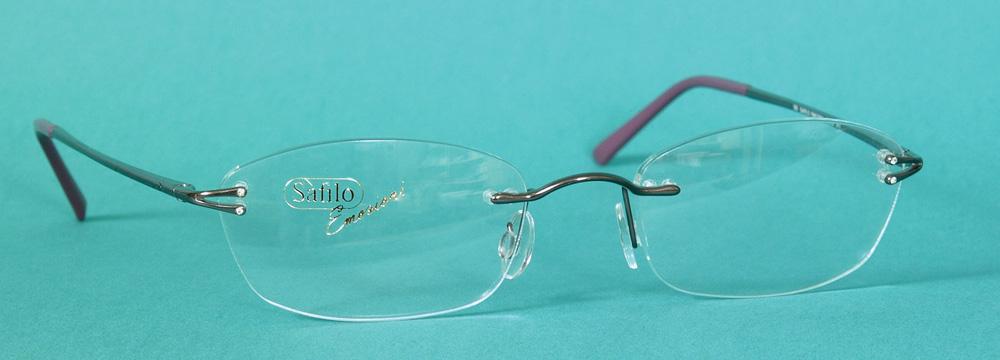
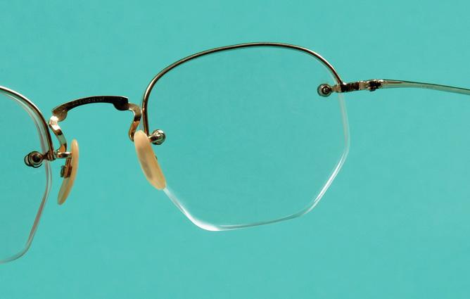
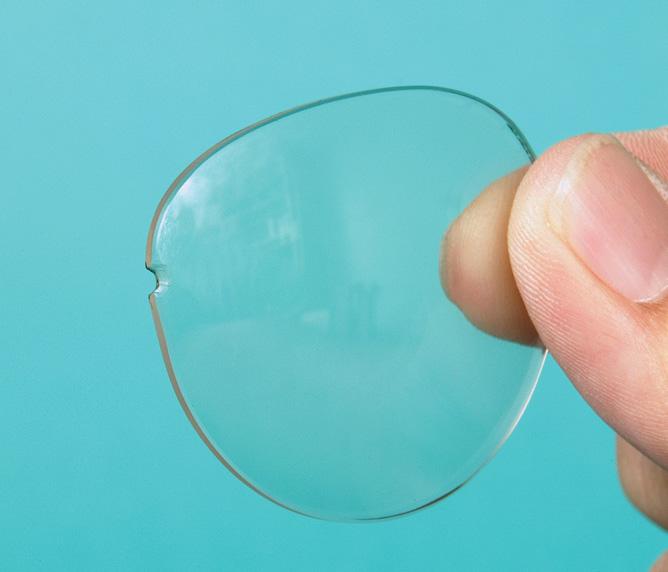
Figure 1-8. An example of a rimless mounting. The central area of the frame is not connected to the endpieces. The only connecting points are the lenses themselves.
surface temporally. Thus there is only one point of attachment per lens (Figure 1-10).
Currently most dispensers refer to any of these three variations of a rimless mounting as “rimless.” They do not differentiate between the three.
Other Mountings
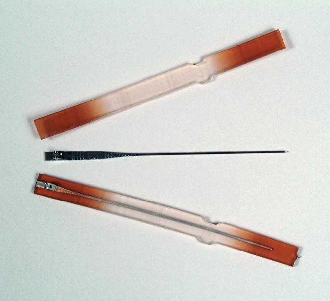
Balgrip mountings secure the lens in place with clips attached to a bar of tensile steel that fits into a nasal and a temporal notch on each side of the lens. The lens can be easily removed by pulling the clips back from the lens. For this reason, this type of mounting can be used with more than one pair of lenses for the same frame. Sunlenses, special purpose lenses, or tinted lenses could then be used interchangeably with the patient’s regular lenses (Figure 1-11). Notches are now more often used in combination with drilled holes in rimless mountings to lend stability to the mounting.
Bridge Area
The bridge area of a frame can be constructed of either plastic or metal. Because of the variety of nose shapes,
A B1-11. A balgrip mounting. In this form of rimless mounting, the slotted lenses (A) are held in place with clips (B)
there is also quite an assortment of bridge constructions in both materials.
Plastic Bridges
The bridge area of a plastic frame is preformed and sits directly on the bridge of the nose. It is important, then, in picking out a plastic frame that the frame fit the nose well, since adjustments to this part of the frame are extremely difficult. Bridge adjustments for certain plastics, such as nylon, carbon fiber and polyamide, are not possible.
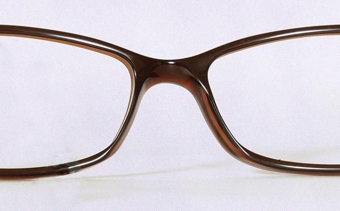
The saddle bridge is shaped like a saddle in a smooth curve and follows the bridge of the nose (Figure 1-12). This spreads the weight of the frame evenly over the sides and crest of the nose.
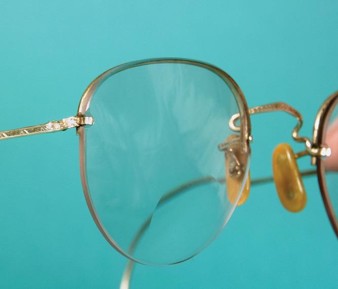
Figure 1-9. A semirimless mounting has a bar behind the top of the lens connecting the endpieces to the bridge area.
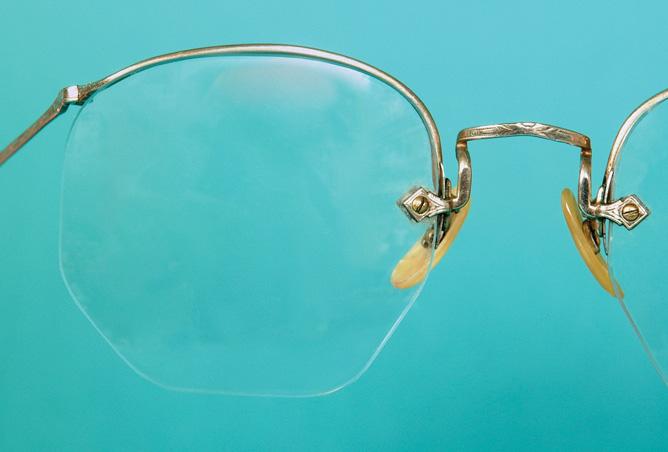
Figure 1-10. A Numont mounting has only one nasal point of attachment per lens.
Figure
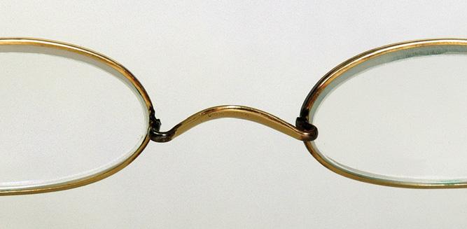
Figure 1-15. Metal saddle bridges were originally designed to rest directly on the crest of the nose. They may still be used as originally designed shown in the frame pictured. Often a metal saddle bridge is just for decorative purposes and is used in conjunction with nosepads.
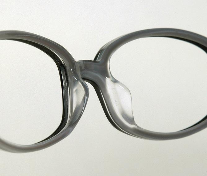
In the modifi ed saddle, the bridge area looks much the same as the saddle bridge does when viewed from the front. The difference is that there are nose pads that are part of the back of the bridge. These pads help to carry some of the weight of the frame (Figure 1-13).
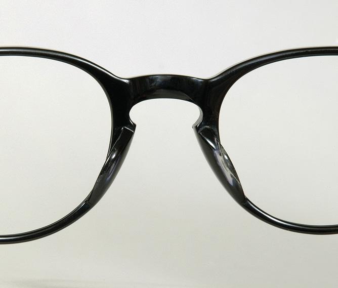
The keyhole bridge is shaped like an old-fashioned keyhole. At the top, the bridge flares out slightly. The bridge rests on the sides of the nose, but not on the crest (Figure 1-14).
Metal Bridges
The bridge commonly used in metal frames is the pad bridge (see Figure 1-8). In the pad bridge, nose pads are attached to the frame by metal pad arms. In this case, the pads alone support the weight of the glasses.
When a metal frame is equipped with a clear plastic saddle-type bridge, the bridge type is referred to as a comfort bridge.
Metal and rimless frames were, and sometimes still are, constructed with a metal saddle bridge∗ (Figure 1-15) and enjoyed widespread use for a period of history. It may yet appear exactly as before or decoratively in conjunction with nosepads.
With rimless mountings, the crest of the bridge does not include the pads or straps, but is the center most area.
Endpiece Construction
Endpiece construction, like the bridge area construction, can be of either plastic or metal.
Plastic Endpieces Construction
There are three general types of endpiece construction in plastic frames (Figure 1-16). The most common
*Historically the metal saddle bridge was called a W bridge.
Figure 1-12. The saddle bridge closely follows the contour of the nose, evenly spreading the weight of the frame.
Figure 1-13. The modified saddle bridge has fi xed nose pads attached at the back to increase the weight-bearing area of the frame.
Figure 1-14. Besides having an identifying shape, the keyhole bridge supports the frame weight upon pads.
endpiece construction is the butt type, in which the front is straight and the temple butt is flat, and both meet at a 90-degree angle. The mitre endpiece causes the frame front contact area and temple butt to meet at a 45-degree angle. In the turn-back type, the frame front bends around and meets the temple end to end.
Metal Endpiece Construction
The traditional metal endpiece has a construction similar to the turn-back endpiece of the plastic frame (Figure 1-17). There are now a wide variety of metal endpiece designs.
Endpieces are also noticeable by their absence. Instead of an endpiece, some frame fronts and temples are made as one continuous piece (Figure 1-18).
Figure 1-18. Some metal endpieces are not really endpieces at all. T he endpiece and temple are one continuous piece of material as in this “wrap” endpiece design.
Temple Construction
Temples also vary greatly in their construction. In general, there are five major categories (Figure 1-19).
1. Skull temples bend down behind the ear and follow the contour of the skull, resting evenly against it. The bent-down portion is narrower at the top of the ear and widens toward the end.
Figure 1-16. Endpieces of plastic frames classified as m itre (A), butt (B), and turn-back (C)
Figure 1-17. This traditional metal endpiece has a turn-back design.
Figure 1-19. Categories of temples are: A, Skull; B, Library; C, Convertible; D, Riding bow (in plastic); E, Comfort cable (in metal).
2. Library temples usually begin with an average width at the butt and increase in width posteriorly. They are practically straight and hold the glasses on primarily by pressure against the side of the head. They are also known as straight-back temples.
3. Convertible temples were originally designed so they could be bent down to take on the form of skull temples, and “converted” from the straight-back to the skull design. Because this temple is versatile and can be made to fit people with a variety of temple length requirements, it is commonly used. However, it now comes already bent down for a certain temple fit. If the bend is in the wrong location, the temple may be easily straightened out and then re-bent to fit the wearer.
4. Riding bow temples curve around the ear, following the crotch of the ear where the ear and the head meet and extend to the level of the earlobe. They are sometimes used in children’s and safety frames.
5. Comfort cable temples are shaped the same as riding bow temples, but are of metal construction with the curl, or behind the ear portion, constructed from a flexible coiled cable.
“Classic” Rimless Fronts
The centerpiece of a rimless front consists of the bridge, pad arms, and pads. These parts are the same as for metal
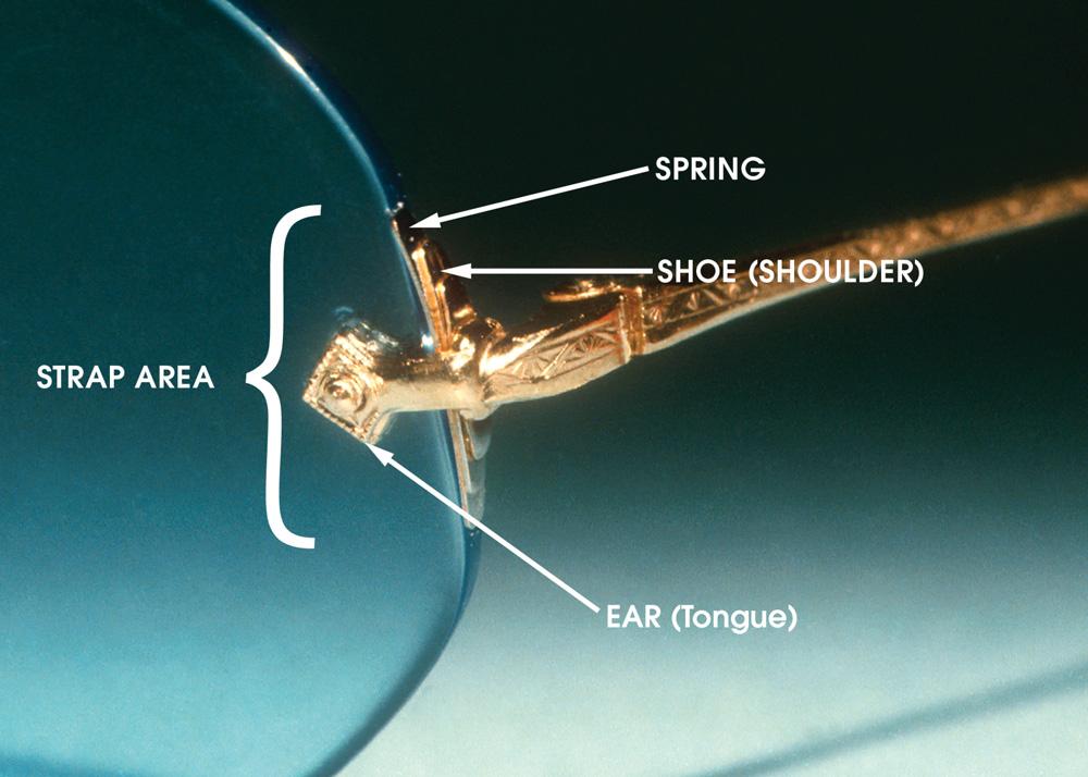
frames. Rimless construction varies considerably. The “classic” rimless point of lens attachment contains a strap or straps. This is the part of the mounting that contacts the front and back surfaces and the edge of the lens, holding the lens in place. The traditional strap consists of the shoe and the ear.
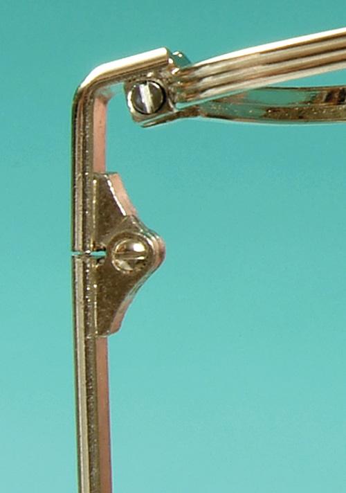
The shoe, also known as the shoulder or collar, contacts the edge of the lens, bracing it and keeping it from rocking back and forth in its mounting. On some traditional mountings, there is a small metal spring between the shoe and the lens, which helps keep the lens tight in the mounting.
The ear, or tongue, is that portion of the strap that extends from the shoe, contacting the surface of the lens. There are sometimes two ears per strap, one on each lens surface, with a screw passing through both ears and the lens to hold the lens in place. The term straps is sometimes used to refer only to the ears (Figure 1-20).
The arm is that part of a semirimless mounting that extends posteriorly along the top edge of the lens (see Figure 1-9). The arm is not to be confused with the pad arm, which is part of the nose pad assembly. This arm is sometimes referred to as a bar or brow-bar.
The endpieces of rimless fronts are the same as those listed for metal frames. In addition, rimless endpieces also have straps to hold the lenses, as well as hinges for temples.
Coloration
Plastic frames may be partially classified by coloration. A solid frame is all one color. A vertically gradient frame is darker all the way across the top, including the bridge, and is lighter across the bottom. A horizontally gradient frame is darker at the temporal portions and lightens toward the central area. Clear bridge frames somewhat resemble the horizontal gradient, but are dark at the top, except for the bridge area. The bridge, along with the lower half of the frame, is clear plastic. The multitude of color combinations available now makes categorization beyond this difficult.
FRAME MATERIALS
Plastic Frame Materials
The fi rst classification of a frame is by the material used in its construction: either plastic or metal. Several types of both are used to make frames.
The fi rst plastics used for spectacle frames were made from bakelite and galalith 1 These did not perform well in cold weather because of their brittleness. Later cellulose nitrate (zylonite) was widely used. Cellulose nitrate accepts a good polish, but is flammable if brought to a sufficiently high temperature. Because of the danger posed, cellulose nitrate has been banned by the FDA and is no longer used for spectacle frames. However, because these zylonite frames were the only plastic frames commonly used for a period of time, plastic frames were known as
“zyl” frames. In spite of zylonite disappearing from the market, the “zyl” nickname for plastic frames remained. Now that nickname is primarily used to refer to cellulose acetate material.
Cellulose Acetate
A material used extensively for spectacle frames is cellulose acetate. The basic cellulose material may be extracted from cotton or wood pulp and then further processed.1 When derived from cotton, the material used is the fiber that adheres to the cottonseed after ginning and is too short to be used for making textiles. These fibers are called cotton linters. 2 This cotton or wood material is treated with a mixture of anhydride and acetic acid using sulfuric acid as a catalyst. Plasticizers and aging stabilizers are then added to this material. 2 Nevertheless, cellulose acetate does become brittle with age.
Some allergies are attributed to wearing cellulose acetate frames, though this is rare. More often skin problems are not so much allergic reactions to the material itself, but to those things which can be absorbed by the material. Higher quality cellulose acetate frames are coated in order to seal the surface. When left uncoated, cellulose acetate may absorb materials which might be allergen producing. A good frame coating will contain a UV inhibitor.* This inhibitor in the coating keeps frame color from fading.
1-20. The strap area in a classic-style rimless mounting has the same construction at both center and endpiece locations. Contemporary rimless mountings do not necessarily have this classic-style construction. *A “UV inhibitor” blocks out the sun’s ultraviolet rays.
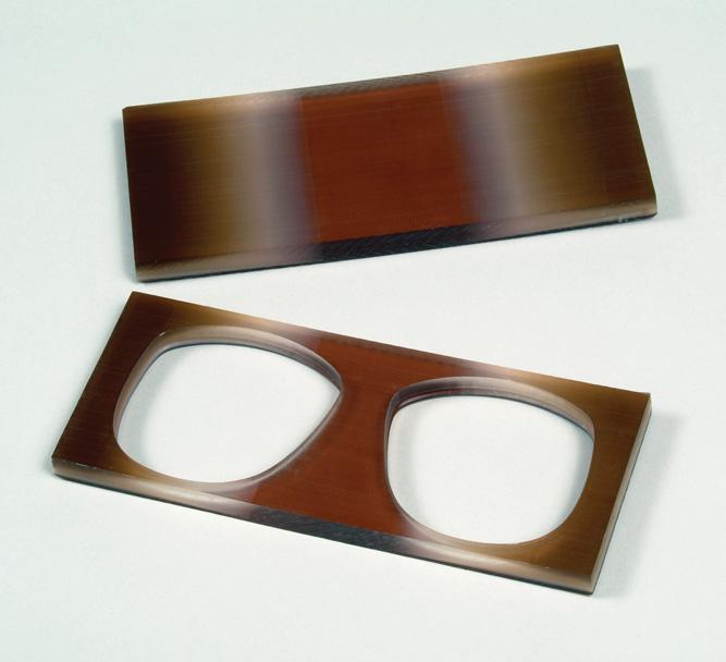
Cellulose acetate can be formed into sheets of plastic from which frame parts can be cut, or it can be made into acetate granules that are used for injection molding. For spectacle frames, cellulose acetate is generally made into sheets and milled (Figure 1-21).
Propionate
Cellulose aceto-propionate, more commonly referred to as propionate, has many of the same characteristics as cellulose acetate and works better for injection molding. Propionate has less color stability than cellulose acetate and, unless it is covered with a high quality framecoating material containing UV absorbers, will fade within a relatively short period of time. Propionate frames are made beginning with granules of the material that are heated until liquid, then injection molded to the desired frame shape. Granules may initially be colorless, allowing the frame parts to be dyed to the desired color after they have been molded. Propionate has a slight weight advantage over acetate, in that it is about three quarters of the weight.
Optyl
Epoxy resin is used for spectacle frames and is known under the trade name of Optyl. A liquid resin and a hardener are mixed together and drawn into the frame molds using a vacuum process. The material is thermoelastic. This means that it will bend when heated and will return to its original shape when reheated. (Cellulose acetate is thermoplastic. This means that it will bend when
Figure
Figure 1-21. Frame fronts and temples can be milled from slabs of cellulose acetate. They are fi nished in steps until being polished, and usually coated to protect the frame material from sunlight and to decrease the possibility of allergic reactions in sensitive wearers. A, The frame front is being milled from a slab of plastic. B, One method for making temples. First the cellulose acetate is formed (top). Then the metal hinge and core (middle) is injected into the plastic (bottom). From this point, the temple is milled to the desired form and shaped.
heated but does not return to its original shape when reheated because it does not have a “plastic memory.”) Optyl is approximately 30% lighter than cellulose acetate. 2 Because of its stability, Optyl is appropriate for those who might be allergic to other types of frame materials. (For more information on working with Optyl material, see Chapter 7, Insertion into an Optyl Frame.)
Nylon and Nylon-Based Materials
Nylon. Nylon is a material of high flexibility. When used alone in spectacle frames, nylon will lose that flexibility unless periodically soaked in water overnight. Otherwise, over time, it will become brittle. “Pure” nylon was previously used extensively for sports eyewear. It has also been used for over-the-counter sunglasses.3 It is now being combined with other material for added strength and stability, remaining a part of the array of frame materials in use. (See Chapter 7, Insertion into a Nylon Frame.)
Polyamide/Copolyamide. Polyamide is a nylonbased material that is quite strong. Because it can be made thinner and is only 72% of the weight of cellulose acetate, polyamide has a real weight advantage. Polyamide frames can be made opaque or translucent. Frames made from polyamide are resistant to chemicals and solvents, and are also hypoallergenic.3 (For more on polyamide frames, see Chapter 7, Insertion into a Polyamide Frame.)
Grilamid. Grilamid is a nylon-based material used in sports and performance type of eyewear. Unlike plain nylon frame material, grilamid has a large variety of color possibilities. Some manufacturers have fused Grilamid with titanium to create a strong, comfortable variation of this frame material.
Carbon Fiber
Carbon fi ber material is used to create a thin, strong frame. This material is made from strands of carbon fibers combined with nylon. It is not adjustable and is consequently used mainly for frame fronts. The temples are generally made from another material. In other words, if a carbon fiber frame does not fit well in frame selection, do not plan on making it fit well later on. The principle advantage is the light weight that can be achieved. Carbon fiber is 60% the weight of cellulose acetate. Not only is the material light weight, but because of its strength, it can also be made thinner. Since carbon is black, frame colors will be opaque and are limited. Some problems may be encountered with breakage in cold weather. Because of the thermal problems, it is imperative that the material not be directly worked with right after it has been outside. (For more information on working with carbon fiber material, see Chapter 7, Insertion into a Carbon Fiber Frame.)
Polycarbonate
Polycarbonate is a material usually associated with lenses, but can be molded into frames. Frames made from polycarbonate are primarily for sport or safety purposes. When made for nonprescription purposes, the lenses and frame are molded as one unit.
Frames (and lenses) made from polycarbonate are very impact resistant. Unfortunately, polycarbonate frames do not work well for conventional eyeglasses because of their resistance to adjustment. They are better suited for
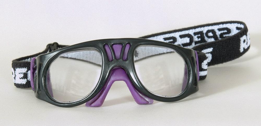
1-22. Polycarbonate sports frames can be ordered from the manufacturer with plano lenses already in place. They can also be ordered without lenses for prescription use.
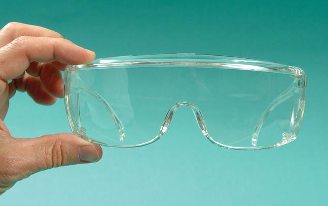
the type of sports glasses that are held in place with elastic straps (Figure 1-22) or for shield types of glasses that may be used either alone or worn over conventional glasses (Figure 1-23).
Kevlar
Kevlar is a material that is also mixed with nylon. It, too, is a strong, lightweight ophthalmic frame material. Kevlar will remain stable over a large temperature range, but is difficult to adjust. Although it becomes pliable with heat, it will not shrink or stretch.
Rubber
Some sports eyewear and sunglass frames may be made from a combination of nylon and rubber. As would be expected, these frames are flexible and will return to their original shape, but are not adjustable.4
Combinations of Plastic Materials
There are numerous possible combinations of plastic materials. These include materials sometimes called
memory plastics. Memory plastics are tough and flexible. They can be bent or twisted and still return to their original shape.
Not all composite plastic materials are memory plastics. Other composite plastics combine various materials to produce frames and frame parts for specific needs and purposes.
Metal Frame Materials
In the past, gold-containing alloys were the more predominant metals used for spectacle frames. (See Chapter 2, Gold Classifications for Metal Frames with Substantial Gold Content.) Today few frames contain any gold.
Great progress has been made in metal frames because of the electrolytic treatment techniques, which allow for corrosion resistance and fi nished beauty. Any nostalgia over the disappearance of gold alloy frames from the marketplace should be dispelled by the beauty and serviceability of the product that has taken its place.
It is also common for frames to be made with more than one material. The temples may be from one material for flexibility, the frame front from another, and the connecting pieces something different still.
Nickel-Based Materials
Nickel is a material that is often used for eyeglass frames. It is strong and malleable. The main disadvantage is the number of people who may have an allergic reaction to nickel. It is reported that 10% of the population may be allergic to nickel.5 Fortunately high-quality ophthalmic frames are coated with a protective material that both prevents corrosion and keeps the metal from coming in direct contact with the skin while the coating remains on the frame.
Pure Nickel. Nickel resists corrosion. Because of malleability, pure nickel frames are easily adjusted. Nickel’s characteristic of accepting color well makes these frames versatile.
Figure
Figure 1-23. Safety frames with plano lenses can be molded as one unit . In the sample shown, both the frames and lenses are molded together from polycarbonate material.
Nickel Silvers. Nickel silvers contain more than 50% copper, 25% nickel, and the rest zinc. But “nickel silver” contains no silver. Copper gives the material its pliability, zinc adds strength, and nickel gives the alloy a whitish appearance. When the nickel content of nickel silver exceeds 12%, the copper color no longer shows through.1 Another name for nickel silver is German silver Monel Metal. Monel is whitish in color, is pliable for good adjustment, resists corrosion, and accepts a high polish. It is made from nickel, copper, iron, and traces of other elements. The largest component of the material (63% to 70%) is nickel. The second largest component is copper. Iron constitutes only 2.5%, and there are traces of silicium, carbon, and sulfur.1 Monel is used quite often as a frame material.
Aluminum
Aluminum is both strong and extremely lightweight. It can be fi nished in a wide variety of colors and does not corrode. Aluminum does not solder or weld well, so must be made such that its parts are assembled with screws or rivets.6 It holds the adjustment well, but has no flexibility. If it bends, it stays that way.
Stainless Steel
In the nineteenth century, some frames were made from regular (nonstainless) steel material. Stainless steel was developed in the early 20th century. It is made mainly from iron and chrome and is highly resistant to corrosion. Stainless steel is strong. When made very thin, it has an element of springiness and flexibility that makes it well suited for temples. Yet that very springiness means that “adjustments are difficult and often do not hold.7” Stainless steel is one of the more nonallergenic materials.
Titanium
Titanium is a versatile and abundant material that has become increasingly common for use in ophthalmic frames. The advantages include the following:
• Titanium is extremely light in weight. When compared with conventional metal frame materials, titanium is 48% lighter.8
• Titanium is very strong, which allows titanium frames to be designed exceedingly thin. Thinness also contributes to still more weight reduction.
• Titanium is very corrosion resistant. This makes titanium an excellent choice for people in hot climates or those working in conditions where they would be perspiring a great deal.
• Titanium is hypoallergenic. It should be noted that titanium is often used in combination with other metals. If the wearer is allergic to another of the metals in the alloy, then, unless the frame is appropriately coated, allergic reactions could still occur. But when titanium is not mixed with other metals, it is the metal of choice for those with skin
allergies related to frame wear. This makes titanium a very attractive frame material for those with skin allergies.
• When used in combination with other metals, titanium allows frames to be made so that they are very flexible. It should be noted that some frames use titanium in combination with nickel to increase flexibility. Without an appropriate coating on the frame, this would increase the likelihood of an allergic response for some.
The disadvantages of titanium are fewer. These include the following:
• Titanium is hard to solder or weld.
• Because the manufacturing process is more demanding, titanium is more expensive than conventional materials.
Titanium Marking Guidelines and Classifications.
The Vision Council of America (VCA) has established voluntary marking guidelines for frames containing titanium. The reason for these guidelines was “to end some of the confusion that arises when frames are labeled ‘titanium’ but are actually only part titanium—or do not contain titanium at all.9 ” Because these are voluntary guidelines, this means that there may still be some confusion in marking. However, if frames are marked according to VCA standards, then the buyer should know what that particular frame contains. To be certified, the titanium content of the frame must be tested by an independent accredited laboratory. Here are the guidelines:10
• Certifi ed 100% Titanium —All major components of the frame are at least 90% titanium by weight and, to assure there will be no problems with wearer allergy, the frame must not contain any nickel (Figure 1-24, A ).
• Certifi ed Beta Titanium —All major components of the frame are at least 70% titanium by weight, and there must be no nickel content (Figure 1-24, B ).
Vision Council of America
Figure 1-24. The Vision Council of America marking guidelines for titanium uses a symbol that would normally appear on the demonstration lens of the display frame. A, Certified 100% Titanium means 90% titanium and there is no nickel contained in the frame. B, Certified Beta Titanium means 70% minimum titanium with no nickel content.
Not included in the Vision Council of American classification is what has been called combination titanium —a name applied to frames with titanium for the major parts of the frame and trim pieces made from other metals.8 The name nickel titanium or shape memory alloy (SMA) is applied to a titanium alloy made with 40% to 50% titanium and the rest nickel.11 Sometimes simply called memory metal, 12 this material is extremely flexible and returns to its original shape after being twisted or flexed. (It should be noted that there will be other types of metal frame materials that will also function like a “memory metal.”)
Bronze
Bronze is a metal alloy traditionally made from copper and tin. It is suited for spectacle frames because it is corrosion-resistant, lightweight, and takes color well.
Magnesium
Magnesium is even lighter in weight than titanium. Frames made from magnesium are extremely lightweight and exceptionally durable. The exterior of the frame is normally sealed because of the corrosiveness of raw magnesium. Magnesium is also used as part of an alloy in combination with other metals.
Other Materials and Alloys
There are other materials that are also suitable for frames, including cobalt, palladium, ruthenium, and beryllium.
As would be expected, there are many different possible combinations of the previously listed metals that may be combined to optimize certain characteristics. Some have trade names applied especially for a particular combination used by a given frame manufacturer. One, for example, called FX9 is a combination of copper, manganese, tin, and aluminum engineered to yield a hypoallergenic, lightweight, and malleable material.13 Another, referred to as Genium, combines 12% carbon, 17.5% to 20% manganese, 1% silicone, 17.5% to 20% chrome, and 58.9% to 63.9% steel. These materials are combined to create a hypoallergenic frame that is thin, strong, lightweight, flexible, and durable.14 As frame designs change, metal alloy combinations will vary to meet these new design demands.
ALLERGIC REACTIONS TO FRAME MATERIALS
As previously noted, most frame manufacturers will use a coating on their plastic frames to protect the frames and also to reduce any possibility of allergic reactions. However, sometimes this is not enough.
To reduce the possibility of a reaction for people who have a history of skin reactions to wearing frames, use frame materials that are known to be hypoallergenic. Here are some that are reported to be hypoallergenic:
• Optyl material
• Polyamide/Copolyamide
• Titanium
• Stainless steel
If a person is already having a reaction to their frame, here are some things that may be done to the frame to reduce allergic reactions:
• Have a clear coat fi nish applied to a frame.
Companies that specialize in frame repairs may of fer this service. (Incidentally, some dispensers have tried to just coat the inside of the temples with clear nail polish to solve the problem. Unfortunately, this does not work for very long.)
• Use ultrathin, clear heat-shrink tubing over the temples. Optical shrink tubing is available from optical suppliers of spare pairs, pliers, and accessories.
If a person has an allergic reaction to nosepads, there are replacement pads available that will eliminate the problem. These pads are:
• Gold-plated metal nosepads
• Titanium nosepads
• Crystal nosepads
(See also the section in Chapter 10 on Hypoallergenic Nosepad Materials.)
For allergic reactions to metal cable temples, use a temple cover to cover the temple. Temple covers come in plastic, vinyl, and silicone materials. There is also “heat shrink” tubing sold for this purpose, which reportedly takes care of eliminating allergic reactions. (For more on this see the section in Chapter 10 on Adding Covers to Cable Temple Earpieces.)
An additional note on allergies : There is a liquid lens liner sometimes used in the groove of a frame to make a loose lens more secure. This material contains latex and should not be used on frames whose wearers have latex allergies.
6. Barnett D: What’s in a frame? Eyecare Business, September, p.76, 1988.
7. DiSanto M: Rimless eyewear: making the right choice, 20/20, New York, NY, 2004, Jobson Publishing.
8. Szczerbiak M: The ABCs of titanium frames, Visioncareproducts.com, vol 2, no 1, January/February 2002.
9. OMA debuts titanium guideline, Eyecare Business, August, p. 22, 1999.
10. Vision Council of America, Titanium marking guidelines, http://www.visionsite.org/s_vision/sec.asp?TRACKID = &CID =266&DID =397, February 2006.
11. Hohnstine, Nicola, Spina: Make it a lite...a titanium lite, 20/20 Online, 30:11, 2003.
13. O’Keefe J: Make mine metal, Visioncareproducts.com, vol 4, April 2004.
14. O’Keefe J: Frame materials go beyond zyl and monel, Visioncareproducts.com, vol 3, May 2003.
12. What are the different frame materials? Essilor website: Http://www.essilorha.com/frames.htm, excerpted from “OLA Perspective on Lenses,” Optical Laboratory Association, 1997.
Profi ciency Test
(Answers can be found in the back of the book.)
Match the name of the frame with its description:
1. ____ Commonly has a metal chassis and plastic top rims.
2. ____ Has two holes per lens and a metal reinforcing arm that follows the upper posterior surface of the lens.
3. ____ Holds the lenses in place only at their nasal edge.
a. Balgrip
b. Half-eyes
c. Combination
d. Semirimless
e. Numont
Match the name of the frame with its description:
4. ____ Made especially for those needing a reading correction but no distance correction
5. ____ Secures the lenses in place with clips attached to a bar of tensile steel that fits into a slot on each side of the lenses
6. ____ Secures the lenses in place by means of a small string that goes around the lenses
a. balgrip
b. half-eyes
c. semirimless
d. nylon cord
Match the following terms:
7. ____ Optyl
8. ____ lorgnettes
9. ____ aluminum
10. ____ half-eyes
11. ____ “shell”
12. ____ convertible
13. ____ nylon cord
14. ____ Numont
15. ____ earpiece
a. hand-held
b. “zyl”
c. reading
d. curl
e. only nasal
f. anodized
g. straight back
h. has memory
i. string mount
16. Which type of temple curves around the ear following the crotch of the ear where ear and head meet, extending to the level of the earlobe? This type of temple is usually plastic, and is often used in children’s and safety frames.
a. library
b. skull
c. riding bow
d. convertible
17. This follows the bridge of the nose smoothly, spreading the weight of the frame and using nose pads attached to the back of the bridge.
a. keyhole bridge
b. modified saddle bridge
c. saddle bridge
d. pad bridge
e. none of the above
Match the description with the correct frame material:
18. ____ A frame material that is generally made into sheets and milled to make frames.
19. ____ A material of high flexibility that will maintain that flexibility when soaked overnight periodically.
20. ____ Frames from this material can be made thin and are lightweight. Frame colors are primarily opaque and some problems may be encountered with breakage in cold weather.
21. ____ Used primarily for sport or safety purposes. Does not adjust well. Does not work well for conventional eyeglasses.
22. ____ Frames made from these materials are made beginning with granules that are heated until liquid, then injection molded to the desired frame shape.
23. ____ A nylon-based material that can be made translucent, not just opaque.
24. ____ This material is made from a liquid resin and a hardener that are mixed together and drawn into the frame molds using a vacuum process.
a. nylon
b. carbon fiber
c. polyamide
d. Kevlar
e. cellulose
acetate
f. polycarbonate
g. propionate
h. optyl
Match the description with the correct frame material so that all answers are used and no answer is used more than once:
25. ____ Is often used for temples because of its strength and flexibility.
26. ____ Extremely light in weight and will not rust. Can be made thin.
27. ____ Is lightweight and can be fi nished in a variety of colors.
28. ____ A synonym for nickel silver.
29. ____ Is whitish in color, pliable, resists corrosion, and accepts a high polish.
30. ____ Resists corrosion, malleable, accepts color well.
a. Monel metal
b. aluminum
c. pure nickel
d. titanium
e. stainless steel
f. German silver
Match the following titanium frame material classifications with the most appropriate answer:
31. ____ Shape memory alloy
32. ____ Certified 100% titanium
33. ____ Certified Beta titanium
a. All major components at least 70% titanium by weight. No nickel.
b. Combination of titanium and nickel.
c. All major components at least 90% titanium by weight. No nickel.
d. All titanium and no other metal present.
e. All major components at least 70% titanium by weight and remainder nickel.
CHAPTER 2
Frame Measurements and Markings
Familiarity with frame measurements and how they are marked is essential to proper ordering of prescription glasses. Knowledge of measurement procedures assures receipt of the proper size when ordering a replacement for a broken part. The purpose of this chapter is to give the reader a complete understanding of frame dimensional properties. The confidence and capability achieved as a result of this is the base on which to develop skill in frame selection.
THE OLDER DATUM SYSTEM
The previously used datum system for measuring lenses was established as a system of reference points for frames and lenses so that placement of lens optical centers and bifocal segment heights would be consistent. With the lens placed as it should sit in the frame, horizontal lines were drawn at the highest and lowest edges of the lens (Figure 2-1). A line drawn halfway between the two horizontal lines and parallel to them was known as the datum line. The width of the lens along this line was called the datum length or eye size. The point along the datum line halfway between the edges of the lens is the datum center. The depth of the lens, measured as the vertical depth through the datum center, was the mid-datum depth. The datum system preceded the currently used boxing system.
THE BOXING SYSTEM
The boxing system improved on the foundation provided by the datum system. The datum system used two horizontal lines—one against the top and the other against the bottom of the lens. The boxing system kept these two horizontal lines and added two vertical lines. These vertical lines are placed against right and left edges of the lens. All four lines form a box around the lens (Figure 2-2).
Horizontal Midline
There is a horizontal line halfway between the top and bottom of the lens. In the datum system, this was called the datum line. This name continues to be used. However, in the boxing system, this line is more com-
monly referred to as the horizontal midline or the 180degree line.
Geometric Center
The center of the lens is the point on the horizontal midline half way between the two lens-bordering vertical lines. It is known as the geometric center or boxing center of the edged lens. This term does not imply anything about the optical positioning of the lens.
Size
The size of the lens then is the length and depth of the box containing the lens. The horizontal length is now commonly referred to as the eye size when referring to the frame and the lens size when referring to the lenses. Both are measured in millimeters.
When most practitioners speak of lens size or eye size, they are referring primarily to the horizontal measure of the lens, denoted by the letter “A” in Figure 2-2. Some frames list an eye size value that is different from and unrelated to the frame A dimension. Such procedures attempt to relate this eye size number to a “fitting value.” This is not a recommended practice and leads to confusion, but is so commonplace that frame reference materials will usually list both an A dimension and an eye size, even if they are the same value.
The letter “B” denotes the vertical measure of the box enclosing the lens. Both “A” and “B” are in a sense independent of lens shape. The letter “C” refers to the width of the lens itself along the horizontal midline.1 (This can vary considerably from the A dimension.) The C dimension of a lens is seldom used. In the older datum system, this was the eye size of the frame. Some people still mistakenly measure the eye size this way.
The C dimension of a lens should not be confused with the “C-size” of a lens. C-size is the circumference of the edged lens and is sometimes used to increase accuracy when duplicating an old lens size when edging.
Measurement
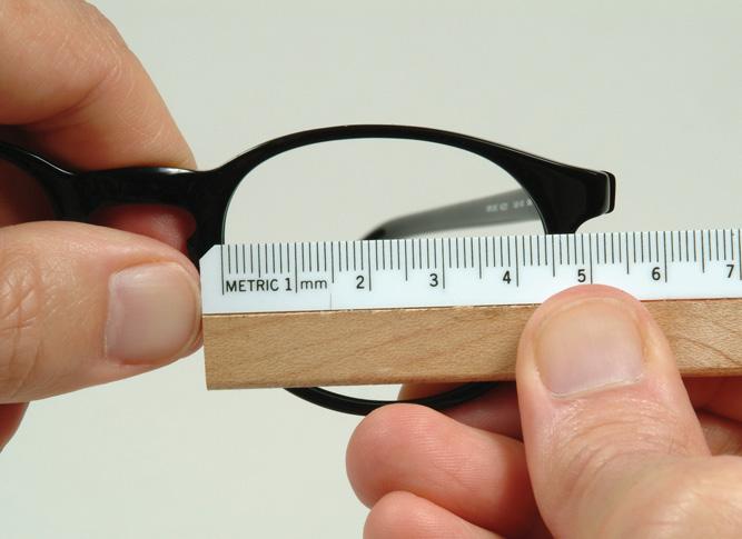
In determining the horizontal boxing dimensions of a frame, the measurement begins at the inside of the groove on the left side of the imaginary enclosing box and extends horizontally across the lens opening to the
farthest part of the groove on the right side of the box (Figure 2-3). Do not fi lt the box.
In measuring a lens, the measurement begins at the apex, or point, of the bevel on the left side of the box enclosing the lens and extends to the apex of the bevel on the right side of the box. Remember, the A dimension is the width of the enclosing box. It is not the width of the lens at the middle of the shape.
Effective Diameter
The effective diameter of a lens is found by doubling the distance from the geometric center of the lens to the apex of the lens bevel farthest from it (see Figure 2-2).
This measurement helps determine the smallest lens blank from which the lens can be cut. (See Chapter 5: Determining Lens Blank Size.)
Frame Difference
The difference between the horizontal and the vertical measurements is known as the frame difference and is measured in millimeters. The larger the difference, the more rectangular the enclosing box appears (Figure 2-4). Frame difference is sometimes referred to as lens difference.
Distance Between Lenses (DBL) or Bridge Size
The boxing system also makes it possible to defi ne the distance between lenses (DBL). The DBL is the distance between the two boxes when both lenses are boxed off in the frame. This is usually synonymous with bridge size, although it is important to note that manufacturers not adhering to the boxing system may mark a bridge size that does not correspond to the distance between lenses.
Datum center
Figure 2-1. In the datum system, the middatum depth may not alway s be equal to the distance between the horizontal tangents. The datum eye size is the width of the lens at the level of the datum line. The datum system eye size and the boxing system eye size are not the same. Some measure the eye size according to the datum system, thinking they are using the boxing system. The two eye size measures are not the same.
Lens size or eyesize
Geometrical center (GC)
Datum line Effective diameter (ED) (ED)
Bridge size or DBL is measured on the frame as the distance from the inside nasal eyewire grooves across the bridge area at the narrowest point (Figure 2-5). This distance is measured in millimeters. Naturally, two frames having the same DBL will not necessarily fit the same person in the same manner because of variations in lens shapes.
Geometric Center Distance (GCD)
The distance between the two geometric centers of the lenses is known as the geometric center distance (GCD).
DBL or Bridge size
Geometrical center distance (GCD or “frame PD”)
Figure 2-2. In the boxing system, the A dimension is the horizontal boxing width. If the frame is properly marked, the eye size will be equal to the A dimension of the frame. The B dimension is the vertical boxing length. The C dimension is the width of the lens along the horizontal midline. This dimension is seldom used today. The C dimension should not be confused with the “C-size” of a lens. The C-size of a lens is the distance around the lens (i.e., its circumference). The dispenser uses the C-size to ensure that a lens ordered by itself (without the frame) will be exactly sized for that frame.
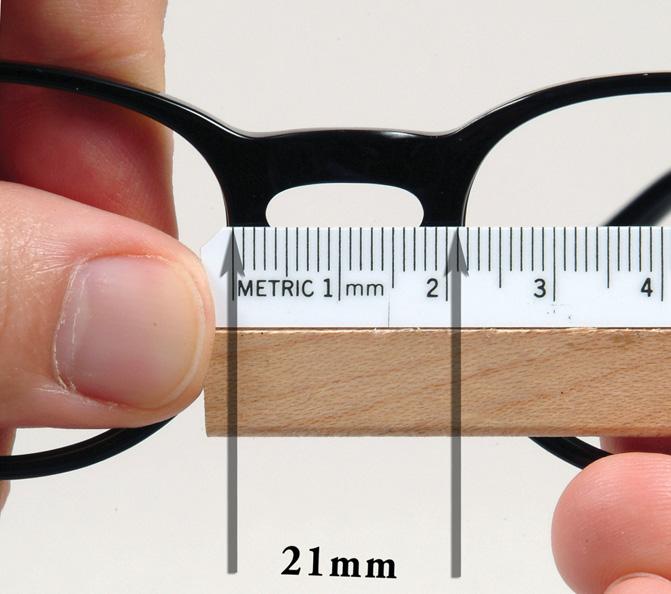
Figure 2-3. To measure the horizontal dimension of a frame, the measurement begins at the inside of the groove on one side and extends across the lens opening to the farthest part of the groove on the other. We cannot see the inside of the groove when looking from the front. This means we can estimate where it will be and hold the ruler so that the zero point is at the position of the left-hand side of the groove. Then we need to read the ruler at the position where the groove will be on the right. If the opening itself is measured, then about ½ mm per side needs to be added to the measure to allow for the depth of the groove. This may vary somewhat, depending upon the depth of the groove.
Figure 2-4. The difference between the horizontal and vertical measurements of a frame is known as the frame difference.
It can be measured more easily as the distance from the far left side of one lens opening to the far left side of the other (i.e., from the left side of one “box” to the left side of the other “box.”) Or the geometric center distance can be calculated by simply adding the eye size to the DBL. The result is the same.
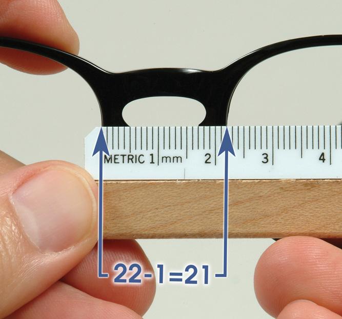
Figure 2-5. A, The DBL or bridge size is measured on the frame as the distance from the inside nasal eyewire grooves across the bridge area at its narrowest point. When measuring the bridge size, we cannot see the inside of the groove and must estimate its location. B, If the measurement is made from lens opening to lens opening, then approximately ½ mm per groove must be subtracted from the measure depending upon the depth of the groove.
The GCD is also known by three other names:
1. Distance between centers (DBC)
2. Frame center distance
3. Frame PD
The term frame PD is commonly used in dispensing, but has no relationship to the wearer’s
interpupillary distance or distance between pupil centers.*
Seg Height
When specifying bifocal or trifocal segment height, the reference points are given in millimeters as either (l) the distance below or above the horizontal midline (called seg drop or seg raise), or (2) the distance from the lower line of the boxing system rectangle enclosing the lens shape (called seg height). In the actual measuring process, the level of the lower line of the box corresponds to the lowest point in the eyewire groove. This level may be different from the depth of the point on the lens edge found directly below the pupil as can be seen by looking carefully at Figure 2-2.
TEMPLE LENGTH
Most temples are currently marked with the total, or overall, temple length. Temple lengths are expressed in millimeters. Temple length may be measured in one of the following ways.
Overall Temple Length
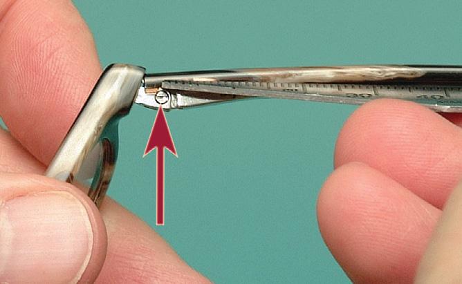
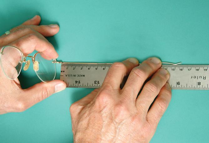
The overall temple length is the distance from the center of the center barrel screw hole to the posterior end of the temple, measured along the center of the temple (Figure 2-6, A ). Many times the center of the barrel
*The term “Frame PD” may have originated when frame size was determined by selecting the correctly fi tting bridge size, then choosing an eye size so that the wearer’s pupils would be at the geometric centers of the frame’s lens openings.
screw hole will match the position of the butt end of the temple. But this is not always the case. Also, when measuring the overall temple length, it is necessary to measure around the bend and not in a straight line, unless of course the temple is straight. The easiest way to do this is shown in Figure 2-7, A through D
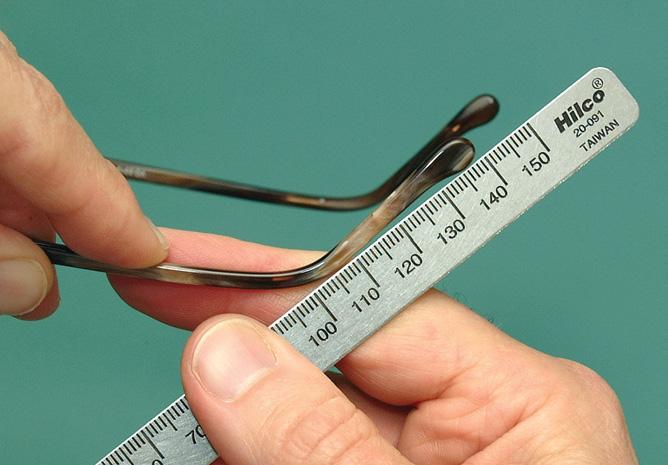
Comfort cable temples are measured in terms of overall length. The actual measurement is done by grasping the tip and extending the temple along the ruler (Figure 2-8).
Length to Bend (LTB)
An older method of measuring temple length is in terms of the length to bend (LTB). This is measured from the center of the barrel to the middle of the bend (Figure 2-6, B ). The distance from the middle of the temple bend to the end of the temple is known as the length of drop (see Figure 2-6, B ).
Front to Bend (FTB)
If the endpieces wrap around in a swept-back manner, there is a distance between the plane of the frame front and the actual beginning of the temple. In this case, the temple length could be specified as frame to bend (FTB) (Figure 2-6, C ), which would be slightly longer than LTB. This measurement method is seldom used.
FRAME MARKINGS
Most frames are marked according to size with three measurements: eye size, DBL, and temple length. Metal frames that are manufactured from “rolled gold” are also marked as to the amount of gold found in the frame. Rolled gold frames were used regularly a good while ago. Any new rolled gold frames are very expensive.
Eye Size and DBL
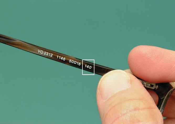
When a frame marking such as 50 20 is seen, it means that the eye size is 50 mm and the distance between lenses is 20 mm. The box between the numbers means that the eye size is measured according to the boxing method; it also serves to separate the two numbers and prevent confusion. The eye size and DBL are sometimes simply marked 50-20 or 50/20.
Location of Markings
On a plastic frame the marking may be found in any of several places. It may be printed on the inside of the nosepad, or it may be found on the upper outer section of the eyewire. Some frames had the size printed on the back side of the endpiece, and the temple must be folded closed to fi nd it. Sometimes the eye size is printed on one endpiece and the DBL on the other. As it should be, temple length is printed on the inner side of the temples. Some manufacturers put all three measurements on the temple. This is done because most frames are sold as a complete unit rather than a frame front with a matching
Figure 2-6. A-C, Various methods used in specifying temple lengt hs.
D
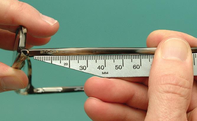
Figure 2-7. Measuring overall temple length. A , Here is a temple marked with a temple length of 140. We will be measuring this temple and comparing our results with what is marked. B, Begin the measurement by placing the zero on the ruler at the center of the hinge barrel, as seen in this measuring view. C, Looking at the temple from the side it is evident that the zero point is not at the butt end of the temple. Often times the position of the center of the barrel and the butt end of the temple are at the same location. It is obvious from the photo that in this case they are not and the beginning point for measuring does not start at the end of the temple. D, Turn the ruler around the temple bend and note where the end of the temple falls on the ruler scale. This is the overall temple length.
Figure 2-8. The overall temple length for a cable temple is obtained by stretching the cable temple along the ruler.
set of temples. Unfortunately this leads to confusion when temples are exchanged.
On metal frames and frames with metal chassis, the eye size and DBL are usually on the inside of the bridge, although occasionally they are printed on the underside of a top reinforcing bar, or again, on the temples.
Frame
Manufacturer Name, Color, and Country of Origin
Frames should also be marked as to country of origin, manufacturer, and frame name. Many frame manufacturers use a number rather than a name. This can be confusing if the frame color is also specified by number and both numbers are stamped on the frame. Consulting a frame reference catalog or database will help.
Safety Frame Markings
Frames that are suitable for use as safety glasses must have “Z87” or “Z87-2” and the name or logo of the manufacturer stamped on the frame front and on both temples. This is as specified by the American National Standards Institute (ANSI) in their standard called American National Standard Practice for Occupational and Educational Eye and Face Protection . The standard is numbered as Z87.1. If a pair of glasses has safety lenses, but is not in a frame marked “Z87” or “Z87-2,” the glasses are not safety glasses. (For more on safety eyewear, see Chapter 23.)
Gold Classifications for Metal Frames With Substantial Gold Content
Metal frames may not have any gold or any significant amount of gold in the frame. This does not imply anything about the quality of the frame. (See Chapter 1 for more on frame materials.) When a frame has a substantial gold content, numbers other than those indicating the size of the frame are printed on the frame to indicate the nature of the gold content. Gold or part-gold articles can be classified as fi ne gold, solid gold, gold fi lled, or having gold plating or gold flashing (Table 2-1).
The color of a frame with gold content has nothing to do with its quality. The color depends on what type
of metal is used in combination with gold to make the gold alloy.
The karat system is used to determine the amount of gold present. The number marked on the article is the amount of gold by weight in comparison to a total of 24 units: an article marked 12k is an alloy made up of onehalf gold and one-half another metal.
Fine Gold
Fine gold is the name used for an article that has no metal in it other than gold. The gold found in it is chemically pure. Although this is the purest form, it is not always the most practical, as is the case in spectacle frames. Frames of fi ne gold would be too malleable and would bend and dent too easily to be practical. Using the karat system, fi ne gold is 24 karats fi ne, which means that by weight, 24 parts out of 24 are gold.
Solid Gold
Solid gold articles are actually an alloy of gold and another metal, a mixture of gold and a base metal. Thus the term is misleading, as it does not mean all gold. The solid gold article is made entirely of the gold alloy. It maintains its luster regardless of how far down it is worn through use.
The symbol q is used to denote a 10k solid gold bridge; the symbol to denote a 12k solid gold bridge.
Gold Filled
Gold-fi lled articles are made of a metal other than gold and then covered with a gold alloy. The term does not indicate that the article is “fi lled with gold,” but rather the opposite: an outer wrapper of gold alloy is “fi lled” with a baser metal. To be classified as gold fi lled, a minimum of one twentieth of the article’s total weight must be gold.
Articles in this classification are marked with a fraction, a karat rating, and the abbreviation for gold fi lled. The fraction shows what part of the total weight of the article is represented by the gold alloy covering. The karat rating shows, as always, the amount of gold by weight in the gold alloy in comparison to a total of 24 units. The GF classifies the article as gold fi lled. For example:
• 1/10—10% of the total weight of the article is alloy.
TABLE 2-1
Gold Classifications
Name Meaning
Fine gold
100% pure gold
Solid gold Gold plus base metal evenly mixed throughout Gold fi lled Base metal inside a “solid gold” coating Gold plating A base metal thinly plated with gold Gold flashing A base metal with gold thinly and quickly applied in a manner similar to that of gold plating
• 12k—12 parts out of 24 parts of the covering alloy by weight are gold.
• GF—The article is classified as gold fi lled.
Thus the article would bear the marking of 1/10 12k GF.
A gold-fi lled article retains its luster until the gold covering eventually wears through.
If a frame is made from parts having different percents of gold, the frame must be marked according to the part containing the least amount of gold. If, for example, the temples are 1/8 12k GF and the front is 1/10 12k GF, the frame must be marked 1/10 12k GF.
Gold Plating
Gold plate articles are made of some other metal, the surface of which is plated with gold, usually by an electrolytic process. Articles classified as gold plate have no minimum requirement as to the total amount of gold used. Gold plate articles maintain luster only until the thin plating is worn through and the base metal is exposed.
Gold Flashing
Gold flashing is a method of gold application that is done in almost the same way that gold plating is done, only faster. Gold flashing is applied using a cyanide-based
bath instead of an acid-based bath. 2 It produces an extremely thin layer of gold. If it were not for the protective coating, which works very well, the gold would not be very durable. A large percentage of spectacle frames have gold flashing and because of the coating are very serviceable.
For a summary of gold classifications, see Table 2-1.
REFERENCES
1. Fry G: The boxing system of lens and frame measurement, part IV, Optical J and Rev Optom 98(17):32-38, 1961.
2. Sipe J: As good as gold, Eyewear Feb:44, 1998.
Profi ciency Test
(Answers can be found in the back of the book.)
There may be more than one correct response to some of the multiple choice questions found below.
1. True or false? In the boxing system, the effective diameter is the diagonal of the box.
2. True or false? The frame difference for a frame with a circular lens shape is always zero.
3. Answer yes or no to each of the following: Is the geometric center distance the same as:
a. the eye size plus the bridge size? (yes/no)
b. the wearer’s PD? (yes/no)
c. the “frame PD”? (yes/no)
4. Would the above GCD change if the lenses were decentered in 3 mm each?
5. A frame has the following dimensions:
A = 51
B = 47
C = 49.5
DBL = 19
Seg drop (distance below the horizontal midline) = 4 mm
What is the seg height?
a. 19.5 mm
b. 20 mm
c. 21.5 mm
d. 23.5 mm
e. none of the above
6. The larger the frame difference, the __________ the lens shape.
a. rounder
b. more squared off
c. narrower
d. wider (i.e., deeper)
7. If a frame’s dimensions are A = 50 and C = 48, with a frame difference of 8, what is B?
a. 58 mm
b. 56 mm
c. 52 mm
d. 46 mm
e. 42 mm
8. A frame is marked 52 18. The lens shape is round. What is the effective diameter of the lens?
a. 70 mm
b. 61 mm
c. 58 mm
d. 52 mm
e. 18 mm
9. What is the geometric center distance of a frame marked 52 17?
a. 52
b. 60.5
c. 69
d. 72
e. equal to the person’s PD
10. What gold classification(s) has/have no minimum requirement as to the total amount of gold used?
a. fi ne gold
b. solid gold
c. gold fi lled
d. gold plated
e. gold flash
11. The color of a frame with gold in it depends on:
a. the quality of gold used.
b. the quantity of gold used.
c. the kind of metal used to make the alloy.
d. the kind of base metal used in the frame.
e. none of the above
12. An article made out of a metal other than gold and then covered with a gold alloy may be:
a. fi ne gold.
b. gold fi lled.
c. gold plated.
d. rolled gold.
e. gold flash.
13. What is the name used for an article that has no metal in it other than chemically pure gold?
a. fi ne gold
b. gold fi lled
c. gold plated
d. gold flash
14. A frame marked 1/10 12k GF
a. has 10% gold by weight.
b. has a 12k solid gold bridge.
c. has a l0k solid gold bridge.
d. is 50% gold by weight.
e. is 10% gold by volume.
Matching
15. ____ A a. 2 × (longest radius)
16. ____ B b. vertical boxing dimension
17. ____ ED c. A + DBL
18. ____ GCD d. eye size
e. C
19. Safety frames must be marked with
a. The manufacturer’s name on both of the temples and the frame front.
b. “Z80” or “Z80-2” on both of the temples and the frame front.
c. “Z87” or “Z87-2” on both of the temples and the frame front.
d. The manufacturer’s name and “Z80” or “Z802” on both of the temples and the frame front.
e. The manufacturer’s name and “Z87” or “Z872” on both of the temples and the frame front.
Measuring the Interpupillary Distance
This chapter provides the methodology for measuring the interpupillary distance (PD). Failure to accurately determine the interpupillary distance results in a misplacement of the optical center of the lenses. This induces unwanted prismatic effects, requiring the wearer to turn his eyes inward, or even outward, to keep from experiencing double vision. Over time, this effort causes visual discomfort and can result in a decreased ability of the eyes to work together in binocular vision.
DEFINITION
The anatomic PD is the distance from the center of one pupil to the center of the other pupil, measured in millimeters. Before ordering prescription glasses or even before doing a visual examination, the distance between the pupils must be determined. It can be measured in a variety of ways.
DISTANCE PD
Binocular PD
The most common method used to measure the PD also requires the least amount of equipment. The technique uses a simple millimeter ruler, commonly referred to as a PD rule.
Technique
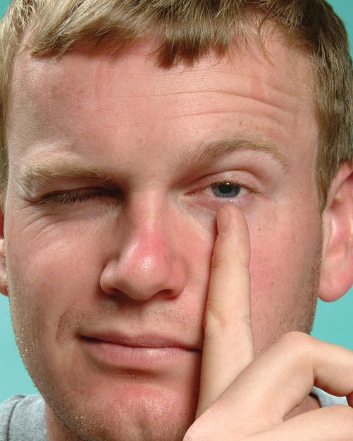
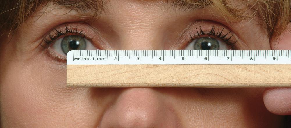
When the PD is to be measured, the dispenser should be positioned at a distance of 40 cm (16 inches) directly in front of the subject, with his or her eyes at the same vertical level as those of the subject. The PD rule is positioned across the subject’s nose with the measuring edge tilted back so that it rests on the most recessed part of the nose. The dispenser holds the PD rule between thumb and forefi nger and steadies the hand by placing the remaining three fi ngers against the subject’s head. The dispenser closes the right eye and sights with the left (Figure 3-1). The subject is instructed to look at the dispenser’s open eye while the dispenser lines up the zero mark of the rule with the center of the subject’s pupil.
When the zero mark is lined up correctly, the dispenser closes the left eye and opens the right. The subject
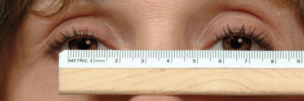
is instructed to look at the dispenser’s open eye. The PD for the distance prescription is read off as that mark falling in the center of the subject’s left pupil (Figure 3-2).
The dispenser now closes the right eye and opens the left. The subject is again instructed to look at the dispenser’s open eye. This step is primarily a recheck to make sure the zero mark is still properly aligned. (This technique is summarized in Box 3-1.)
When difficulty is experienced in determining the exact center of the pupil, the edge of the pupil may be used as a measuring point if both pupils are the same size. Measurement is read from the left side of one pupil to the left side of the other. Measuring from the inside edge of one pupil to the inside edge of the other would give an artificially low reading; from the outside edge of one pupil to the outside edge of the other, an artificially high reading.
When a person has dark irises or unequally sized pupils, it may be difficult to use either the center or the edge of the pupil. In this case, the dispenser may use the limbus edge—the sharp demarcation between white sclera and dark iris (Figure 3-3). (Because the pupil is displaced 0.3 mm nasal ward from the center of the limbal ring,1 a limbal measure will be approximately 0.5 mm greater than the measure found using pupil centers.) The same rule must be applied when using the limbus edge as when using the pupil edge: the same sides of the limbus (both left or both right) must be used, or an extremely large error is induced.
Common Diffi culties and Their Solutions
Dispenser Cannot Close One Eye. Occasionally the person doing the measuring is unable to close one eye independent of the other. This can be remedied by occluding (covering) the eye with the free hand. The practice of holding the lid down with one fi nger gives an unprofessional appearance, especially when wearing glasses. Occluding the eye with the hand held flat appears to be a natural part of the test and does not reveal a person’s inability to close only one eye.
Dispenser Visually Impaired in One Eye. If the dispenser is blind in one eye, or has visual acuity too poor to allow the ruler to be read accurately, then the technique is modified. The dispenser places the good eye
directly in front of the subject’s right eye and at the normal distance. The zero mark is lined up as usual. The dispenser then moves sideways until the good eye is positioned in front of the subject’s left eye and the measurement is read. Unfortunately this method can easily lead to parallax errors. The most desirable solution for someone with this difficulty is to use another type of instrument that only requires the use of one eye.
Subject Is Strabismic. The strabismic subject, whose eyes are in a tropic position (i.e., with one eye pointing in a different direction from the other) presents a special problem, since the PD rule method of measurement may then give an artificially high or low reading. To determine a true reading, simply cover the subject’s eye not
3-1. Position of the dispenser for beginning the PD measurement using just a PD ruler.
being observed. This ensures that the subject is fi xating with the eye under observation and ensures that it is not turned unless eccentric fi xation is present. Even if eccentric fi xation is present, the PD measurement is still correct, since the subject never uses this eye in any other position relative to the dominant eye.
In some instances where one eye turns out constantly, the prescribing doctor may determine that the wearer is better served if the lenses are centered in front of the pupils, even for the eye that is turned. This will require that a separate measure be taken for each eye. One measurement will then be considerably larger than the other.
Subject Is an Uncooperative Child. If the subject is young or uncooperative, making normal PD measurements impossible, the dispenser may have to take a canthus-to-canthus measurement. (The canthus is the corner of the eye where the upper and lower lids meet.) This is done by measuring from the outer canthus of one eye to the inner canthus of the other eye. Unfortunately,
BOX 3-1
Steps in Measuring the Binocular Distance PD
1. Dispenser positions at 40 cm (16 in).
2. Dispenser closes right eye, subject fixates on dispenser’s left eye.
3. Dispenser lines up zero point on subject’s right eye at the pupil center, left pupillary border, or left limbus.
4. Dispenser closes left eye, opens right eye; subject fixates right eye.
5. Dispenser reads off scale directly in line with left pupil center, left pupillary border, or left limbus.
6. Dispenser closes right eye, opens left; subject fixates left eye.
7. Dispenser checks to make sure zero point is still correct.
Figure 3-2. The dispenser uses his or her left eye to establish the zero point of the PD rule in the center of the pupil of the subject’s right eye as shown here. The subject is looking at the dispenser’s left eye. Next the subject looks at the dispenser’s right eye. The dispenser uses his or her right to read the pupillary distance at the center of the subject’s left eye. (This is not what is seen in this photo.)
Figure
this measurement is not entirely exact, since the inner canthi of the eyes encroach farther across the sclera with younger children.
Common Causes of Errors
There are several common causes of errors inherent in using a PD rule. 2
1. There will be an error in measurement if the measurer’s PD differs significantly from the subject’s because the lines of sight are not parallel. For example, if the measurer’s PD is 16 mm larger than the subject’s, the reading will be 1 mm too high because of this parallactic error.
2. The above error will be increased if the PD rule is not tilted on the subject’s nose so that the scale is in the most recessed area. The most recessed area corresponds to the approximate position where the spectacles will be worn.
3. Just as error will be increased when the measurer’s PD is significantly different from the subject’s, the parallactic error will also be increased even more if the dispenser is too close to the subject. Too close is closer than the normal 40 cm (16 inch) distance.
4. A significant error will be induced if the subject is strabismic (one eye turns in or out) or if the subject does not fi xate binocularly* during the PD measurement.
5. An error can result if the subject’s head moves.
6. An error can result if the person measuring moves his or her head.
7. An error will result if the person measuring does not close or occlude one eye at a time to ensure sighting from directly in front of the subject’s eye under observation.
8. The subject may not look directly at the measurer’s pupil during the test, as he or she should, which will result in an error.
*What does “not fixating binocularly” mean? It means that one eye may have a tendency to turn in or out when the subject is not concentrating. In simple terms, they will only be using one eye to see instead of both eyes. When this does happen, one eye usually turns outward somewhat and the measurement is then too large.
Monocular PD
Since faces are not always symmetrical, it is often necessary to specify the PD for each eye independently. The main goal in taking the PD is to eventually place the optical centers of the lenses directly in front of the subject’s eyes to prevent any undesired prismatic effect. If one eye is set closer to a person’s nose than is the other and the optical centers of the lenses are placed symmetrically in the frames, the wearer’s lines of sight will not pass through the optical centers of the lenses. The error is not too serious if the lenses are of the same power and are not strong. If, however, one lens is very different from the other, the centers must be placed accurately to prevent unwanted binocular prismatic effects (Figure 3-4). Monocular PDs are also important when using aspheric lenses or high index lenses, including polycarbonate lenses. High index lenses have more chromatic aberration than crown glass or regular (CR39) plastic lenses. The negative effect of chromatic aberration on vision is increased if the eye is not looking through the optical center of the lens. (For more information on high index lenses, see Chapter 23. For more information on aspheric lenses, see Chapter 18.)
Procedure for Measuring Monocular PDs Using a Ruler
The monocular PD is best taken using a pupillometer. When a pupillometer is not available, monocular PDs are taken by measuring from the center of the nose to the center of the pupils. The procedure consists of the following three steps:
1. Measure the binocular PD as described earlier in the chapter. Use the center of the pupil as the reference point.
2. Before moving the ruler, note the scale reading on the ruler at the center of the nose. This is the right monocular PD.
3. Subtract this reading from the binocular reading to obtain the left monocular PD.
For example, the binocular PD is 66. The scale reading at the center of the nose is 32. The monocular PD for the right eye is then 32. To calculate the monocular PD
Figure 3-3. When the subject has dark irises, the outside edge of the limbus may be used as the zero reference point and the inside limbal edge of the other eye as the measuring point.
Figure 3-4. Here the PD has been measured binocularly as shown on the top measurements. However, t he wearer has very different monocular PDs. Even though the distance PD is 64, the monocular PDs are not 32 and 32. Instead they are 30 and 34. When the lenses are made as if the wearer had 32/32 monocular PDs, in this case there will be unintended Base Out prism caused by the misplaced lenses.
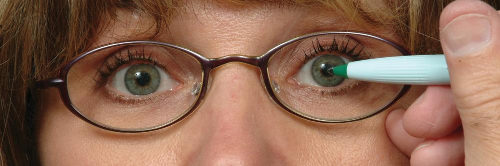
Figure 3-5. To measure monocular PDs using a marking pen and a frame with lenses in the frame, the same procedure is followed as would be used with a ruler. It is essential that the wearer be looking at the dispenser’s eye that is directly in front of the eye being measured. In other words, to mark the location of the wearer’s right pupil center, the wearer looks at the dispenser’s open, left eye. (The dispenser’s right eye is closed.) To mark the location of the wearer’s left pupil center, the wearer looks at the dispenser’s open right eye. (The dispenser’s left eye is closed.)
for the left eye, subtract 32 from 66, to get a reading of 34. The procedure is the same as in taking a binocular PD measurement, except that the two readings are independent of one another and, for purposes of measuring, the center of the pupil is always used. (There are other methods that are considerably more dependable than this method in their ability to yield consistently accurate results.)
Procedure for Measuring Monocular PDs Using the Frame
One error inherent in using a ruler alone appears when a person has an asymmetrical nose. An asymmetrical nose often occurs when a nose has been broken. In this case, the frame positions itself somewhat to the left or right. For the lenses to be accurately placed, this factor must be taken into account. It is possible to use an overhead transparency marking pen and the glazed* lenses
*Glazed lenses are also called “coquilles,” “dummy lenses,” or “demo lenses.”
in the sample frame. If the sample frame does not have glazed lenses, clear tape may be placed over the lens opening of the empty frame.
The procedure for measuring monocular PDs begins by adjusting the frame. The frame should occupy the exact position it will have with the lenses in place. The dispenser should be at the same level as the wearer and approximately 40 cm away. The dispenser closes the right eye. The wearer is instructed to look at the dispenser’s open left eye. Since there is no ruler used, the dispenser uses an overhead transparency marking pen and marks a cross on the right glazed lens. If there is no lens in the frame, the clear tape placed over the lens opening is marked instead, directly over the center of the wearer’s right pupil (Figure 3-5).
Next the dispenser closes the left eye and opens the right eye. The subject is instructed to look at the dispenser’s open eye. The dispenser then marks a cross on the lens or tape directly over the left pupil center.
Because of the movement involved in marking pupil centers and the ease with which unintentional head
BOX 3-2
Steps in Measuring Monocular PDs Using the Sample Frame
1. The selected frame is adjusted in exactly the same manner as it will be when worn.
2. Dispenser positions at 40 cm from the wearer and at the same level.
3. Dispenser opens left eye, closes right eye, and instructs wearer to look at dispenser’s open (left) eye.
4. Dispenser marks location of wearer’s right pupil center on glazed lens.
5. Dispenser opens right eye, closes left eye, and instructs wearer to look at dispenser’s open (right) eye.
6. Dispenser marks location of wearer’s left pupil center on glazed lens.
7. Dispenser rechecks the locations of the marked crosses by repeating steps 3 and 5 and notes the positions of the marked crosses.
8. If one or both crosses are wrong, the frames are removed and the cross(es) erased using a damp cloth.
9. When crosses are accurate, monocular PDs are measured from frame center to cross center.
movement can occur, it is important that these markings be carefully rechecked.
When the dispenser is confident that pupil centers are accurately marked, the frames are removed and the distances from the center of the bridge to the center of each cross are measured and recorded. (These steps are summarized in Box 3-2.)
PD Measuring Instruments
The interpupillary distance is most easily measured by using an instrument especially designed for this purpose. Readings taken using this instrument are not nearly as subject to parallax errors as those taken using a PD rule. Such a device also solves the problems caused when the person doing the measuring is monocular or is amblyopic in one eye.
Most instruments have an occlusion system, which allows for individual monocular measurements, with each eye fi xating alternately in cases of strabismus.
A well-designed PD measuring instrument should rest against the bridge of the subject’s nose exactly as a frame would. This most accurately approximates the way the glasses will position themselves. It should also position the measuring plane at the approximate spectacle plane.
The subject will see a ring of white or colored light around a dark, central dot within the instrument. The dispenser will see the subject’s eye and a scale appearing on it, from which a direct measure is read. Alternately, in some instruments, a split image of the pupil may be seen.
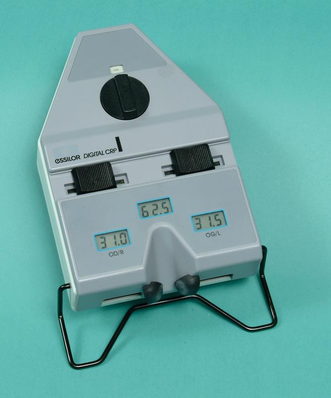
Figure 3-6. The digital version of Essilor’s pupillometer displays monocu lar PDs for the right and left eyes, as well as the binocular PD. It can be set to measure distance or near PDs.
Instruments Using Corneal Refl exes
Although some instruments use a method of taking the PD where the reference point is the geometric center of the pupil itself, the popular alternate corneal-reflex method is used in instruments such as the Essilor pupillometer (Figure 3-6) or the Topcon PD-5, PD Meter. The instruments are supported by means of pads positioned so as to cause the instrument to rest on the nose where the average frame would rest. This is superior to a forehead support system used alone.
The dispenser asks the subject to hold his or her end of the pupillometer so that the pads rest on the nose (Figure 3-7). The forehead support should be against the forehead. The dispenser uses one eye to look into the instrument. (A real advantage for dispensers with good vision in only one eye.)
An internal light produces an image by reflection on each cornea, and the hairline within the device is moved until coincident with this corneal reflection (Figure 3-8). The measurement is assumed to correspond with the subject’s line of sight, but is an objective measurement of the position of the corneal reflection rather than the position of the line of sight. In addition to a distance PD, near PD may be measured for near points from 30 or 35 cms to infi nity.
The line of sight is defi ned as a line passing from the center of the pupil to the object of regard. This is the line that desirably passes through the optical center of