Switch-ModePowerSupplies,SecondEdition:SPICE SimulationsandPracticalDesigns
https://ebookmass.com/product/switch-mode-power-suppliessecond-edition-spice-simulations-and-practical-designs/
Instant digital products (PDF, ePub, MOBI) ready for you
Download now and discover formats that fit your needs...
Designing Control Loops for Linear and Switching Power Supplies: A Tutorial Guide – Ebook PDF Version
https://ebookmass.com/product/designing-control-loops-for-linear-andswitching-power-supplies-a-tutorial-guide-ebook-pdf-version/
ebookmass.com
Practical Rust Projects - Second Edition Shing Lyu
https://ebookmass.com/product/practical-rust-projects-second-editionshing-lyu/
ebookmass.com
Psychophysics, Second Edition: A Practical Introduction Kingdom
https://ebookmass.com/product/psychophysics-second-edition-apractical-introduction-kingdom/
ebookmass.com
Tiempo extraño 2018th Edition Joe Hill
https://ebookmass.com/product/tiempo-extrano-2018th-edition-joe-hill/
ebookmass.com
Introduction to Sonography and Patient Care First Edition, (Ebook PDF)
https://ebookmass.com/product/introduction-to-sonography-and-patientcare-first-edition-ebook-pdf/
ebookmass.com
The Price of Freedom: Financing French Resistance in World War II David Foulk
https://ebookmass.com/product/the-price-of-freedom-financing-frenchresistance-in-world-war-ii-david-foulk/
ebookmass.com
Cecil Essentials of Medicine (Cecil Medicine) 10th Edition Edward J. Wing Md Facp Fidsa (Editor)
https://ebookmass.com/product/cecil-essentials-of-medicine-cecilmedicine-10th-edition-edward-j-wing-md-facp-fidsa-editor/
ebookmass.com
What's the T?: The Guide to All Things Trans And/or Nonbinary Juno Dawson
https://ebookmass.com/product/whats-the-t-the-guide-to-all-thingstrans-and-or-nonbinary-juno-dawson/
ebookmass.com
The Transhumanist Movement Francesco Paolo Adorno
https://ebookmass.com/product/the-transhumanist-movement-francescopaolo-adorno/
ebookmass.com
Ukraine And The Art Of Strategy Lawrence Freedman https://ebookmass.com/product/ukraine-and-the-art-of-strategylawrence-freedman/
ebookmass.com
357Type2b ProportionalPlusaPole
358Type3 OriginPolePlusTwoCoincidentZero-PolePairs
359SelectingtheRightAmplifierType
36AnEasyStabilizationTool ThekFactor
361Type1Derivation
362Type2Derivation
363Type3Derivation
364StabilizingaVoltage-ModeBuckConverterwiththekFactor
365ConditionalStability
366IndependentPole-ZeroPlacement
367CrossingOverRightattheSelectedFrequency
368ThekFactorversusManualPole-ZeroPlacement
369StabilizingaCurrent-ModeBuckConverterwiththekFactor
3610TheCurrent-ModeModelandTransientSteps
37FeedbackwiththeTL431
371AType2AmplifierDesignExamplewiththeTL431
372AType3AmplifierwiththeTL431
373BiasingtheTL431
374TheResistiveDivider
38TheOptocoupler
381ASimplifiedModel
382ExtractingthePole
383AccountingforthePole
3.9OperationalTransconductanceAmplifiers
310ShuntRegulators
3101SPICEModeloftheShuntRegulator
3102QuicklyStabilizingaConverterUsingtheShuntRegulator
311Small-SignalResponseswithPsimandSimplis
WhatIShouldRetainfromThisChapter References
Appendix3AAutomatedPole-ZeroPlacement
Appendix3BATL431SpiceModel
3B1ABehavioralTL431SpiceModel
3B2CathodeCurrentversusCathodeVoltage
3B3OutputImpedance
3B4Open-LoopGain
3B5TransientTest
3B.6ModelNetlist
Appendix3CType2ManualPole-ZeroPlacement
Appendix3DUnderstandingtheVirtualGroundinClosed-LoopSystems
3D1NumericalExample
3D2LoopGainIsUnchanged
Chapter4BasicBlocksandGenericSwitchedModels
41GenericModelsforFasterSimulations
411In-LineEquations
42OperationalAmplifiers
421AMoreRealisticModel
422AUC384XErrorAmplifier
43SourceswithaGivenFan-Out
44Voltage-AdjustablePassiveElements
441TheResistor
442TheCapacitor
4.4.3TheInductor
4.5AHysteresisSwitch
46AnUndervoltageLockoutBlock
47LeadingEdgeBlanking
48ComparatorwithHysteresis
49LogicGates
410Transformers
4101ASimpleSaturableCoreModel
4102MultioutputTransformers
411AstableGenerator
4111AVoltage-ControlledOscillator
4112AVoltage-ControlledOscillatorFeaturingDeadTimeControl
412Genericcontrollers
4121Current-ModeControllers
4122Current-ModeModelwithaBuck
4.12.3Current-ModeInstabilities
4124TheVoltage-ModeModel
4125TheDutyRatioGeneration
4A5Inductance
4A6AvoidingSaturation
FurtherReading
Appendix4BFeedingTransformerModelswithPhysicalValues
4B1UnderstandingtheEquivalentInductorModel
4B2DeterminingthePhysicalValuesoftheTwo-WindingTModel
4B3TheThree-WindingTModel
References
Chapter5.SimulationsandPracticalDesignsofNonisolatedConverters
51TheBuckConverter
511A12-V,4-AVoltage-ModeBuckfroma28-VSource
512TheacAnalysis
5.1.3TransientAnalysis
514ThePowerSwitch
515TheDiode
516OutputRippleandTransientResponse
517InputRipple
518A5-V,10-ACurrent-ModeBuckfromaCarBattery
519TheacAnalysis
5110TransientAnalysis
5111ASynchronousBuckConverter
5112ALow-CostFloatingBuckConverter
5113ComponentConstraintsfortheCCMBuckConverter
52TheBoostConverter
521AVoltage-Mode48-V,2-ABoostConverterfromaCarBattery
522TheacAnalysis
5.2.3TransientAnalysis
5.2.4ACurrent-Mode5-V,1-ABoostConverterfromaLi-IonBattery
525TheacAnalysis
526TransientAnalysis
527InputFilter
528ComponentConstraintsfortheBoostConverter
53TheBuck-BoostConverter
531AVoltage-Mode12-V,2-ABuck-BoostConverterPoweredfromaCarBattery
532TheacAnalysis
533TransientAnalysis
534ADiscontinuousCurrent-Mode12-V,2-ABuck-BoostConverterOperatingfromaCarBattery
535AcAnalysis
536TransientAnalysis
537ComponentConstraintsfortheBuck-BoostConverter
References
Appendix5ATheBoostinDiscontinuousMode,DesignEquations
5A1InputCurrent
5A2OutputRippleVoltage
Chapter6.SimulationsandPracticalDesignsofOff-LineConverters—TheFrontEnd
61TheRectifierBridge
611CapacitorSelection
612DiodeConductionTime
613RmsCurrentintheCapacitor
614CurrentintheDiodes
615InputPowerFactor
6.1.6A100-WRectifierOperatedonUniversalMains
6.1.7Hold-UpTime
618WaveformsandLineImpedance
619In-RushCurrent
6110VoltageDoubler
62PowerFactorCorrection
621DefinitionofPowerFactor
622NonsinusoidalSignals
623ALinktotheDistortion
624WhyPowerFactorCorrection?
625HarmonicLimits
626ANeedforStorage
627PassivePFC
628ImprovingtheHarmonicContent
629TheValley-FillPassiveCorrector
6.2.10ActivePowerFactorCorrection
6211DifferentTechniques
6212ConstantOn-TimeBorderlineOperation
6213FrequencyVariationsinBCM
6214AveragedModelingoftheBCMBoost
6215Fixed-FrequencyAverageCurrent-ModeControl
6216ShapingtheCurrent
6217Fixed-FrequencyPeakCurrent-ModeControl
6218CompensatingthePeakCurrent-ModeControlPFC
6219AverageModelingofthePeakCurrent-ModePFC
6220HystereticPowerFactorCorrection
6221Fixed-FrequencyDCMBoost
6222FlybackConverter
6223TestingtheFlybackPFC
63DesigningABcmBoostPfc
631AverageSimulations
632ReducingtheSimulationTime
633Cycle-by-CycleSimulation
634TheFollow-BoostTechnique
WhatIShouldRetainfromThisChapter
References
Appendix6ADiodeandBulkCapacitorCurrentConstraints:ADifferentView
6A1DesignExample
6A2SelectingaNormalizedValuefortheBulkCapacitor
Appendix6BASmall-SignalModeloftheBCMBoostConverterPowerFactorCorrectorOperatedinVoltage-orCurrent-ModeControl
6B1Current-ModeControl
References
Chapter7.SimulationsandPracticalDesignsofFlybackConverters
71AnIsolatedBuck-Boost
72FlybackWaveforms,NoParasiticElements
73FlybackWaveformswithParasiticElements
74FlybackConverterOperatedinQuasi-Resonance
741DerivingtheSwitchingFrequency
75ObservingtheDrainSignal,NoClampingAction
76ClampingtheDrainExcursion
77Dcm,LookingforValleys
78DesigningtheClampingNetwork
7.8.1TheRCDConfiguration
782Selectingkc
783CuringtheLeakageRinging
784WhichDiodetoSelect?
785BewareofVoltageVariations
786TVSClamp
7.9Two-SwitchFlyback 710ActiveClamp
7.12.2Start-UpResistorDesignExample
7123Half-WaveConnection
7124GoodRiddance,Start-UpResistor!
7125High-VoltageCurrentSource
7126TheAuxiliaryWinding
7127Short-CircuitProtection
7128ObservingtheFeedbackPin
7129SensingtheSecondary-SideCurrent
71210ImprovingtheDriveCapability
71211OvervoltageProtection
713CompensatingOverPower
7131TransferringPowerwithaFlybackConverter
7132ThePropagationDelayAffectstheMaximumOutputPowerLevel
7133WhyLimitMaximumPower?
7.13.4HowDoWePracticallyLimittheMaximumPower?
7135TheTransitionfromCCMtoDCM
7136DerivingVariables
7137ComputingtheTransmittedPower
7138OverPowerProtectioninCCM
7139OverPowerProtectionwithaQRFlybackConverter
71310ReducingtheMaximumCurrentatHighLine
71311CalculatinganOPPResistance
714StandbyPowerofConverters
7141WhatIsStandbyPower?
7142TheOriginsofLosses
7143SkippingUnwantedCycles
7144SkippingCycleswithaUC384X
7145FrequencyFoldback
7.15A20W,Single-OutputPowerSupply
7.16A90W,Single-OutputPowerSupply
717A35W,MultioutputPowerSupply
718ComponentConstraintsfortheFlybackConverter
WhatIShouldRetainfromThisChapter
References
Appendix7AReadingtheWaveformstoExtracttheTransformerParameters
Appendix7BTheStress
7B1Voltage
7B2Current
Appendix7CTransformerDesignforthe90-WAdapter
7C1CoreSelection
7C2DeterminingthePrimaryandSecondaryTurns
7C3ChoosingthePrimaryandSecondaryWireSizes
7C4ChoosingtheMaterial,BasedontheDesiredInductance,orGappingtheCoreIfNecessary
7C.5DesignsUsingIntusoftMagneticDesigner
Reference
Appendix7DASmall-SignalModeloftheFlybackConverterOperatedinQuasi-Resonance
7D1ABCMFlybackConverter
7D2ApplicationExample
7D3TheAcAnalysis
7D4NumericalApplication
Reference
Appendix7ESwitchingLosseswithaNonlinearlyVaryingParasiticCapacitor
Reference
Appendix7FTestingTransformerCoreSaturationLevel
Reference
Chapter8.SimulationsandPracticalDesignsofForwardConverters
81AnIsolatedBuckConverter
811NeedforaCompleteCoreReset
8.2ResetSolution1,aThirdWinding
821LeakageInductanceandOverlap
83ResetSolution2,aTwo-SwitchConfiguration
831Two-SwitchForwardandHalf-BridgeDriver
84ResetSolution3,theResonantDemagnetization
85ResetSolution4,theRCDClamp
86ResetSolution5,theActiveClamp
861AverageSimulationsoftheActiveClampForwardConverter
862AcResponseoftheActiveClampForwardthroughCycle-by-CycleSimulation
87SynchronousRectification
8.8MultioutputForwardConverters
881MagneticAmplifiers
882SynchronousPostregulation
883CoupledInductors
89Small-SignalResponseoftheForwardConverter
891VoltageMode
892CurrentMode
893MultioutputForward
810ASingle-Output12-V,250-WForwardDesignExample
8101MOSFETSelection
8102InstallingaSnubber
8103DiodeSelection
8104Small-SignalAnalysis
8105TransientResults
8106Short-CircuitProtection
811ComponentConstraintsfortheForwardConverter
WhatIShouldRetainfromThischapter
References
Appendix8AHalf-BridgeDriversUsingtheBootstrapTechnique
Appendix8BImpedanceReflections
Appendix8CTransformerandInductorDesignsforthe250-WAdapter
8C1TransformerVariables
8C2TransformerCoreSelection
8C3DeterminingthePrimaryandSecondaryTurns
8C4ChoosingthePrimaryandSecondaryWireSizes
8C5GappingtheCore
8C6DesignsUsingIntusoftMagneticDesigner
8C.7InductorDesign
8C8CoreSelection
8C9ChoosingtheWireSizeandCheckingthedcResistiveLoss
8C10CheckingtheCoreLoss
8C11EstimatingtheTemperatureRise
Reference
Appendix8DASmall-SignalModelfortheActiveClampForwardConverterOperatedinVoltageModeControl
8D1RevealingPWMSwitches
8D2Large-SignalSimulations
8D3Small-SignalModeling
8D4TheMagnetizingCurrentResonantCircuit
8D5FinalLap:AssociatingAlltheBlocks
8D6TestingaPrototypeResponseintheBench
Reference
Appendix8EWebContent
Conclusion
Index
ABOUTTHEAUTHOR ChristophePBassoiscurrentlyanengineeringdirectoratONSemiconductorinFrance,wherehehasdevelopednumerouspopularswitching powersupplycontrollers,forinstance,forthenotebookadapterbusinessHeistheauthorofseveralbooksonpowerelectronics,including McGraw-Hill’sSwitch-ModePowerSupplySPICECookbook,and,recently,hereleasedatitle100%dedicatedtoloopcontrol,Designing ControlLoopsforLinearandSwitchingPowerSupplies HeregularlyteachesprofessionalseminarsatIEEE-sponsoredAppliedPower ElectronicsConferencesandoftenpublishesarticlesintrademagazinessuchasPETandtheonlinenewsletterHow2Power MrBasso graduatedfromtheMontpellierUniversityin1985,andhereceivedhisMSEEinpowerelectronicsfromtheNationalPolytechnicInstituteof Toulousein2008Heholds29patentsinthefieldofpowerelectronicsandheisanIEEESeniorMember
Iamgladtointroducethesecondeditionofmy2008bookSwitch-ModePowerSupplies:SPICESimulationsandPracticalDesigns Iwouldlike tothankallthereaderswhohavecontributedtomakethefirsteditionasuccessIreceivednumerouswarmandsupportivemessagesfromall aroundtheworldanditisextremelyrewardingWithoutyou,thisnewbookwouldnotexistSomeofthesereadershavebeenkindenoughto reporttyposanderrorstheyfoundinthefirsteditionIcompiledthemthroughouttheyearsandIusedthelisttocleanequationsandfigures
Revisingabookisnotaneasytask,assomereaderswillobjectthatthereistoolittlerenewedcontenttomakeitanewbookwhileothers complainthatthisneweditionrepresentsacompletelydifferentdocumentthanthefirstonetheybought!Needlesstosay,tryingtopleaseboth partiesisaperilousexercise.Loyaltomyoriginalapproach,IaddedtopicsinwhichIdetailedthemathematicaltreatmentsothatyoucanfollow andlearnfromthebook.InChap.1,itisthecaseforrmsconstraintsconcerningthebasicswitchingcells.Inmostoftheavailablebooks,authors giveformulaswithoutfoundingequationsandoftenlimittheiranalysistooneconductionmode.Here,bothconductionmodesareexploredand detailed,withclearsummarytablesattheend.NumerousMathcad®sheetsareprovidedonlineatwww.mhprofessional.com/Bassotoletyou evaluateyourownconfigurations.Small-signal-wise,Chap.2hasbeenexpandedwiththePWMswitchatworkinadiscontinuousconduction modeboostconverterandthederivationofafeedforwardcompensatorgain.Chapter3nowincludesOTA-basedcompensatorsandoffersa transistor-levelTL431model.Chapter4includesseveralrevisionsonblockssuchastheD-flip-flopandtheleadingedgeblankingtimer.Chapter 6nowincludesacompletesmall-signalanalysisoftheborderline-operatedboostPFCcircuitoperatedinvoltageorcurrentmode.Chapter7 coversindetailalloverpowerphenomenainfixed-frequencydiscontinuousorcontinuousflybackconverters,withoutforgettingquasi-resonance. Asmall-signalmodelofaQRflybackconverterispresentedinoneoftheappendices.Finally,Chap.8includesanewsmall-signalmodelofthe activeclampforwardconverteroperatedinvoltage-modecontrol.
Ihopeyouwillenjoyreadingthissecondedition,inparticularthenewlyaddedmaterialsDespiteallmyefforts,sometyposormistakesmayhave escapedmyattentionandIwouldbegratefulifyouwouldsendyourcorrections/remarkstocbasso@wanadoofrAsusual,Iwillkeeparecordof thesefindingsandcompiletheminmywebpagehttp://cbassopagesperso-orangefr/SpicehtmforthebenefitofthereadingcommunityIthank youinadvanceandwishyouthebestofluckforyourdesigns!
CHRISTOPHEPBASSO
ACKNOWLEDGMENTS Mywarmestthanksandlovegofirstofalltomydearfamily:Anne,mywife,andmytwobelovedchildren,LucileandPaulRevisinganentire900pagebookcannotbedoneovernightandIamgratefulIcouldspendendlesshourscorrectingandwritingnewparagraphswithoutaffectingfamily lifeNowthatitisdone,Iwillenjoyhiking,cycling,reading,snowshoeing,andspendingleisuretimewithyouallagain!
ThebookrevisioncouldnothavebeenenvisagedwithoutthehelpandinvolvementofmanypeopleIwishtothankJoëlTurchi,myfriendand colleagueatwork,whoisalwaysavailabletodiscusstechnicalsubjectsforhoursandreviewmyworkThesediscussionsalsotookplacewiththe applicationteamwithwhomIamluckytowork:ThierrySutto,StéphanieCannenterre,YannVaquette,andDrJoséCapillaTheykindlyreviewed thissecondedition’smaterialsSpecialthanksgotoAlainLapradeofONSemiconductorinEastGreenwichwhokindlyreviewedseveral chapters
Iwishtoalsoexpressmygratitudetomybelovedparents,MicheleandPaulBasso,whoboughtmemyfirstpowersupplywhenIwas14andlet medevelopmypassionforelectroniccircuits,attheexpenseofnumerousbreakertripsAswehavereturnedtomyyouth,“merci”toteachers suchasRenéVinciandBernardMétralfromthe“Clos-BanetLycée,”whoinstilledtheirpassionandknowledgeintotherestlessstudentthatI wasAtthesametime,IpublishedmyfirstarticleinRadio-Plans(1982),thankstomyfriendsClaudeDucrosandChristianDuchemin,last editors-in-chiefofthenow-defunctmagazineFinally,ClaudeDucheminfromtheMontpellierUniversityaddedthefinishingtouchesandplugged myfingersintotheswitchingpowersupplyworld!
BoththefirstandsecondeditionsofthisbookincorporatecommentsandrecommendationsfromprestigiouspeopleIhavebeenhonoredto workwithTheirnamesfollowandIwishtothankthemwarmlyfortheamountoftimetheyspentreviewingthefirstedition’smaterialsandtracking inaccuracies:DrVatchéVorpérian(JetPropulsionLaboratory),DrRichardRedl(Elfi),EdBloom(e/jBLOOMassociatesInc),DrRaymond Ridley(RidleyEngineering),DrIvoBarbi(PowerElectronicsInstituteoftheFederalUniversityofSantaCatarina),JeffHall(ONSemiconductor), DhavalDalal(Acptek),andnotforgettingMonsieurMullett(formerlywithONSemiconductor)forthetwoappendiceskindlycontributedon magneticdesigns!Also,ChristianZardini(retiredfromtheENSEIRBschool),DrFrankiPoonandDrSC Tan(PowerELabandtheHongKong PolytechnicUniversity),DrDylanLu(SydneyUniversity),ArnaudObin(formerlywithLordEngineering),DrVRamanarayanan(Electrical EngineeringDepartmentoftheIndianInstituteofScienceinBangalore),DrJean-PaulFerrieux(Laboratoired’ElectrotechniquedeGrenoble), SteveSandler(AEiSystems),DrDidierBalocco(formerlywithSaftPowerSystems),andPierreAloisi(formerlywithMOTOROLA)
IwouldalsoliketothankthepeopleatIntusoft,LarryandLiseMearesandalltheirgreatsupportteam(George,Farhad,Everett,Tim),whohelped meduringthetestingphaseofthenumerousbookexamplesIwanttothanktheeditorsofsimulationsoftwarewhohavekindlycontributed simulationexamples
Finally,thankyoutoMikeMcCabe,atMcGraw-Hill,forgivingmetheopportunitytopublishaneweditionofmyoriginalbook
Ae
thecross-sectionareaofamagneticmaterial
BVDSS theMOSFETdrain-sourcebreakdownvoltage
B theinductionfluxdensityinamagneticmedium
BCM borderlineconductionmode(sameasCrM)orboundaryconductionmode
Br theremanentinductionfluxlevelwhenthemagnetizingfieldiszero
Bsat theinductionfluxdensityatwhichμrdropsto1
CCM continuousconductionmode
CL closedloop
Clump thetotalcapacitanceseenonaparticularpointofthecircuit
CrM criticalconductionmode
CTR currenttransferratioforanoptocoupler
Dord theconverterdutyratio;alsonotedd1inDCManalysis
D′ord′ thedutyratioofftime(d′=1′d)
d2,d3 thedutyratioofftimesinDCM:1=d1+d2+d3
DT thedeadtimebetweenswitchingevents
D0 theconverterstaticdutyratioduringabias-pointanalysis
thepeak-to-peakripplecurrentintheinductor
equivalentseriesresistance
equivalentseriesinductance
thecrossoverfrequency,where|T(fc)|=0dB
Fsw theswitchingfrequency
Fline themainsfrequency
G(f) thecompensatorfrequencyresponse
Gfc thegaindeficit(orexcess)attheselectedcrossoverfrequencyfc
φ thefluxinamagneticmedium
φm thephasemarginreadatthecrossoverfrequencyfc
gm thetransconductanceofanoperationaltransconductanceamplifier(OTA)
themagnetizingforce
Hc
thecoercivefieldwhichbringsthefluxdensitybacktozero
H(f) theconverterpowerstage(theplant)frequencyresponse
Ia,Ip,andIc theaveragecurrentsflowinginoroutofthePWMswitchterminals
C thecurrentinsideacapacitorC
d thediodecurrent
D theMOSFETdraincurrent
in theinputcurrentofagivenconverter
Iin,rmsorIac theinputrmscurrentinamainspoweredconverter
IL thecurrentinaninductorL
Imag thetransformermagnetizinginductorcurrentinaforwardconverter
Iout theoutputcurrentofagivenconverter
Ip theprimarycurrentinatransformer-basedconverter
Ipeak thepeakcurrentinagivenelement Isec thesecondarycurrentinatransformer-basedconverter
kD
kd
thederatingfactorfortheMOSFETBVDSS
thederatingfactorforthediodeVRRM
l,le,lm themeanmagneticpathlength
lg thegaplengthinatransformer
Lp theprimaryinductorofatransformer(usuallyinaflybackconverter)
LHP lefthalf-planezero(LHPZ)orpole(LHPP)locatedintheleftportioninans-planeplot
Lleak thetransformertotalleakageinductanceseenfromtheprimary(alloutputsshorted)
Lmag themagnetizinginductanceofatransformer(usuallyinaforwardconverter)
Lsec thesecondary-sideinductorofatransformer M theconverterconversionratio,Vout/Vin Mc theslopecompensationlevelinacurrent-modeconverter(perDrRidley’sdefinition) Mr
theexternalrampcoefficientincurrent-modedesigns(asapercentageoftheoffslope)
thepermeabilityofamaterialrelativetothatoffreespace
theinitialpermeabilitydescribestheslopeofthemagnetizationcurveattheorigin
thepermeabilityoftheair
theturnsratioofatransformernormalizedtoitsprimarywindingForinstance,ifNp=10andNs=3,thenN =03
openloop;forinstanceagain,aphase,oranoutputimpedance
theconductionlossesofanelementimplyingaresistivepathandarmscurrentsquared
powerfactor
powerfactorcorrection
theconverteroutputpower
thepeakinversevoltageadiodehastosustain
switchinglossesofanelementimplyinganoverlapareabetweenacurrentandvoltage
t
Q thequalitycoefficientofafilterorthequantityofelectricity(coulombs) Qr thechargethediodeneedstoevacuatebeforerecoveringitsblockingcapabilities
thetotaldioderecoverycharge
G theamountofcoulombsyouneedtobringtotheMOSFETforitsfullenhancement
rCf theseriesresistorofthecapacitor;alsonotedtheESR
rLf theseriesresistoroftheinductor;alsonotedtheESL
RDS(on) theMOSFETdrain-sourceresistancewhenturnedon
rms rootmeansquare
RsenseorRi thesenseresistorinacurrent-modeconverter;sometimescalledtheburdenresistor
RHP righthalf-planezero(RHPZ)orpole(RHPP)locatedintherightportioninans-planeplot
SaorSe theexternalcompensationramp
SonorS1 theinductorslopeduringtheontime
SEPIC single-endedprimaryinductanceconverter
SMPS switch-modepowersupply
SPICE SimulationProgramwithIntegratedCircuitEmphasis
SofforS2 theinductorslopeduringtheofftime
Sr theexternallyimposedblockingslopewhenblockingadiode
tc therectifyingdiodeconductiontime
td thebulkcapacitordischargetime
ton thetimeduringwhichthepowerswitchisturnedon
toff thetimeduringwhichthepowerswitchisturnedoff
tprop thepropagationdelayofthelogicblocksinacontroller
thereverserecoverytimeofadiode
TVS transientvoltagesuppressor
T(f) thecompensatedloopgain
Tj thejunctiontemperature
Tsw theswitchingperiod
Vac,Vcp theaveragevoltagesacrossthePWMswitchterminals
Vbulk thebulkvoltage
Vbulk,maxorVpeak thebulkvoltageatthehighestline(therippleisneglectedinthiscase)
VC thevoltageacrossacapacitorC
Vce(sat) thesaturationvoltageofabipolartransistor
Vclamp theclampingvoltagelevel
VDS theMOSFETdrain-sourcevoltage
Vf thediodeforwarddrop
VGS theMOSFETgate-sourcevoltage
Vin theinputvoltageoftheconverter
Vin,rmsorVac themainsrmsvoltage
VL thevoltageacrossaninductorL
Vleak thevoltageacrosstheleakageinductance
VminorVbulk,min thebulkvalleyvoltage,lowlineonly
VOS thevoltageovershootontheRCDclamp
Vout theoutputvoltage
Vpeak thepeakamplitudeofsawtoothrampinavoltage-modePWM
Vp thepeakundershootvoltageinresponsetoaloadstep
Vr thesecondary-sidevoltagereflectedontheprimarysideinatransformer-basedconverter
Vsense thevoltagedevelopedacrossthesenseresistorinacurrent-modeconverter
Vripple thepeak-to-peakripplevoltage
VRRM thediodemaximumrepetitivereversevoltage
ζ theGreekletterzeta,representativeofthedampingfactor[oftenmixedupwithζ(xi)]
CHAPTER1 INTRODUCTIONTOPOWERCONVERSION UserfriendlinessisakeyfactorforthecommercialsuccessofanysimulationprogramThegrowingcomplexityofintegratedcircuitsand equipmentmakesthisaspectincreasinglyimportantDespitenumerouspublicationsdevotedtotheSimulationProgramwithIntegratedCircuit Emphasis(SPICE),itstillscaresthenovicewhenitsnameismentioned
Developedinthemid-1970sattheUniversityofCalifornia,Berkeley,theSPICEprogram’sprimaryaimwastofulfilltheneedsoftheelectronics industry mainlyintegratedcircuitmakersHowever,withthesupportandfundsfromprivateeditors,theSPICEprogramhasevolvedovera numberofyearsintomanypracticalandaffordablepackages,withemphasisonprovidingbothlow-pricedandfriendlyaccesstobeginners SPICEcansignificantlyhelpyouspeedupthedesignphaseoftheequipmentyouarecurrentlyworkingon,evenifSPICEisnotabletogenerate anelectronicschematicbyitselfSPICEisinherentlyefficientbecauseifyoustartworkingwithanunfamiliarconcept,itwillquicklyenableyouto graspthefullmeaningofanyparticulararchitecturebyunveilingitspeculiarwaveformsYoucanthususethesimulatortogaininsightintothe circuityouhavetobuildandalsoensureallparametersaretakenintoaccountbeforethebreadboardphase
Thisbookisintendedforpowersupplydesigners,expertsintheirfields,aswellasforbeginnerswhowouldliketounderstandthesecretsof switch-modepowerconversionManipulatingvirtualcomponentsonacomputerscreen,withoutthehazardsofhighvoltage,offersaninteresting andsafewaytolearnthetechniqueFurthermore,the“experience”gainedinsimulation,anditisalsotrueforexpertssimulatinganovelconcept, willletyoufeelmorecomfortablewhenbreadboardingonthebench
11“DOYOUREALLYNEEDTOSIMULATE?” Howmanytimeshaveyouheardthisquestionwhenaskingforasimulationpackageoranewcomputer?Thefollowingstatementsdonot representanexhaustivelistofprosaboutcomputersimulation,buttheycancertainlybeconsidereda“helplist”availableduringthenegotiations:
1Hereisanargument:SimulationcanavoidwasteoftimeandmoneyWithitsinherentiterativepower,SPICEcoversnumerousapplication casesinwhichyoucouldeasilydetectanydesignflaworproductweaknessThestabilityofaclosed-loopSMPSrepresentsatypicalapplication whensomekeyfeedbackelementsaremoving(ie,thevariableloadthataffectsapole)orstarttodegradewithtemperatureandaging(asthe electrolyticequivalentseriesresistor)Moreover,designideascanalsobetestedorassessedinasnapshotthroughacomputerand,iftheyare worthtrying,furtherrefinedinthelab
2.Youcanstarttoworkonaprojectbydownloadingcomponentsmodelsandbecomingfamiliarwiththekeyelements,beforegoingtothebench orwaitingforthesamplestobedelivered.Oncethesesamplesarrive,youwillhavealreadygainedinsightbyprototypingwiththesimulatorand thepracticaldebugphaseonthebenchwillclearlytakebenefitfromyourfirstcomputer-basedexperiments.
3Simulatetestmeasurementswheneveryoudonotowntheadequateequipment:BandwidthmeasurementsrepresentagoodexampleIfyou cannotaffordanetworkanalyzer,thenaprovensmall-signalmodelcanhelpyoustarttorefineyourfeedbackloopWhenrunonthefinal prototype,stabilityassessmentswillbefasterandmoreefficient
4.Powerlibrariesaresafe:Theyletyouexperiment“whatif”whenamperesandkilovoltsareflowinginthecircuitwithoutblowingupintheevent ofawrongconnection!Also,theyletyouseehowyourdesignreactstoashort-circuitoftheoptocouplerortheopeningofaresistorSPICEcan begintogiveyoutheanswer
1.2WHATYOUWILLFINDINTHEFOLLOWINGPAGES ThisbookthoroughlydetailstheadvantagesofSPICEtoletyouunderstand,simulate,test,andfinallyimprovetheswitch-modepowersupply (SMPS)youwanttodesignByprovidingyouwithspecificsimulationrecipes,thisworkintendstofacilitateasmuchaspossibleyourSMPS designUnlikeotherbooks,theauthorstrivestobalancethetheoreticalcontent,necessarytounderstandandquestionsimulationresults,with practicaldesignexamplesThisisdevelopedthroughouttheeightchaptersofthebook
Chapter1explainsswitch-modepowersupplytechniquesandtypesofconverters,anditintroducesafewimportantresultstohelpyoubetter understandaveragingtechniquesThissecondeditionincludesthecomprehensivederivationofrootmeansquare(rms)currentconstraintsofthe basicswitchingcells,buck,boost,andbuck-boostoperatedincontinuousordiscontinuousconductionmodesAsusual,Ihavedetailed derivationstepssothatyoucanfollowandlearnthetechniqueincaseyouencounteradifferentswitchingcellAnewappendixhasbeenadded Chapter2explainshowaveragemodelswerederived,anddifferenttypesaredescribed.Agoodcomprehensionofthischapterisfundamental: ItwillhelpyouquestioncertainweirdSPICEdataresultingfromabadmodelimplementation.Ifyoudonotunderstandthewaythemodelhas beenderived,youwillobviouslyfacesomedifficultiesinresolvingtheseissues.InChap.2,youwillalsolearnhowtowireanaveragemodeland runbasicsimulations.Thissecondeditionaddsthedescriptionofthefeedforwardmodulator.Iaddedmoredetailstothesmall-signalPWM
switchInparticular,Ishowhowkeepingthesamevoltage-modeaveragemodeltowhichyouadda“dutyratiofactory”turnsthemodelintoa simplifiedversionofcurrentmodeAnappendixhasbeenaddedfocusingontheDCM(discontinuousconductionmode)voltage-modeboost small-signaltransferfunctionClosingtheloopisobviouslyanimportantaspectofconverterdesignthatisoftenoverlookedThisisnotthecase here,andChap3willguideyouthroughcontrolloopdesign,againusingpracticalexampleswithaTL431andnotopampsonly,asoftenseenin theliteratureOTA(operationaltransconductanceamplifiers)compensatorsarenowpartofthischapter,coveringtypes1and2Acomplete transistor-levelmodeloftheTL431hasbeenaddedtoitsdedicatedappendixBecausenoteveryintegratedcircuitalwayscomeswithaSPICE model,Chap4describeshowthegenericswitchedmodelsarederivedThischapterwillinterestthosewhowanttostrengthentheirknowledge ofSPICEmodelwritingAmorerobustD-flip-flopisdescribedandseveralnewcircuitshavebeenaddedChapter5describespracticaldesigns ofthethreebasicnonisolatedtopologies,includingthefront-endfilterBeforeanalyzingoff-lineconverters,Chap6showshowtodesignthe rectifyingsectionandexplainsthevariouspowerfactorcorrectiontechniquesSmall-signalresponseofthepopularborderline-operatedpower factorcorrection(PFC)hasbeenaddedinadedicatedappendixChapter7isentirelydedicatedtotheflybackconverter,withspecificdesign examplesattheendAnewsectiononoverpowerhasbeenaddedanditcoversalloperatingmodes,includingQRconvertersAnappendix givesthesmall-signalresponseoftheQRconverterNonlinearcapacitorswitchinglossesareexploredinadedicatedappendixFinally,the forwardconverterappearsinChap8,againassociatedwithadesignexampleThecoupled-inductorssectionhasbeenupdatedanda completesmall-signalmodeloftheactive-clampconverteroperatedinvoltage-modeispresentedwithexperimentalresults
VersionsyntaxisasignificantissuewithSPICEMostSPICEeditorsdealwithaproprietarysyntax,sometimesSPICE3conformant,thatmakes translationfromoneplatformtoanotheradifficultandpainfulexerciseToallowtheuseofdifferentsimulators,thestandardmodelspresented throughoutthepagesarecompatiblewithIntusoftIsSpice(SanPedro,Calif)andCADENCE’sPSpice(Irvine,Calif)
Tohelpyouquicklycopyandpasteexamples,simulationfileshavebeenmadeavailablefordownloadfromaMcGraw-Hillwebsite.Pleasecheck App8EfordetailsSomeselectedsimulationexamplesareofferedinIsSpiceandPSpicesyntax,andyoucaneasilyloadthemonyour computerifyouhaveoneofthesesoftwareprogramsForstudentsornewcomerstotheSPICEworld,somedemonstrationversionswillletyou openfilesandsimulatesomeofthem(thosedemosaresize-limited)togiveyouatasteofwhatthefullversioncandoTheMcGraw-Hill downloadpagecontainsPowerPoint®andMathcad®filestoletyoukeyinyourowndesignparametersandchecksmall-signalresponseorrms constraintsofthebasicswitchingcells
Forprofessionalpowersupplydesigners,anotherlibraryfileisseparatelydistributedThisfilecontainsthedesignexamplespresentedinthe bookplusnumerousotherindustrialapplicationsusingrealcontrollersPleasevisittheauthor’swebsitefordistributiondetails (http://cbassopagesperso-orangefr/Spicehtm)
13WHATYOUWILLNOTFINDINTHISBOOK ThisbookdoesnotdescribethewaySPICEoperates,nordoesitsolvetypicalelectriccircuitsItassumesthatthereaderisalreadyfamiliarwith thebasicsofSPICEsimulationsNumerousbooksandpapersareavailableonthesubjectastheReferencessectiondetails[1,2]Whenever possible,theextendedbibliographywillguideyourchoiceifyouwishtostrengthenyourknowledgeinaparticulardomain,suchassome topologiesthatyouareunfamiliarwithIfsometheoreticalresultsaresometimesdeliveredjust“asis,”westronglyencouragethereadertodig furtherintotheappropriateliteratureandacquirethetheorythatprecedestheresult
ThebookfocusesonlyonasystemapproachNoSPICEdescriptionoftypicaldiscretepowerelementssuchasdiodes,MOSFETs,etc,is proposed
Finally,hereistheimportantstatement,probablythemostinterestingone!SPICEdoesnotreplacethebreadboardphase,nordoesitshieldyou fromwritingequationsorunderstandingelectronicsItlookslikeasimplesentence,buttheauthorhasoftenbeenconfrontedbydesigners showingboardsinthetrashandclaiming,“ButSPICEsaiditwouldwork!!”Yes,allideasworkonpaperuntiltheyfacethesolderingiron condemnation UseSPICEasadesigncompanion,acircuitinsiderthatcanrevealwaveformsdifficulttoobserveButalwaysquestionthe delivereddata:Isthistherealbehavior,haveIbeenmisledsomewhere,doesasimplecalculationmoreorlessconfirmwhatIsee?
Afterthisbriefintroduction,itistimetoplungeintotheintricacyofSMPSdesignandsimulationwithSPICE
1.4CONVERTINGPOWERWITHRESISTORS Intheelectronicsworld,differenttypesofcircuitriesmustcohabit:logicdevices,analogcircuits,microprocessors,andsoonUnfortunatelyforthe designer,thesecircuitsdonotcopewithasingle,fixed,powersupplyrail:Amicroprocessororadigitalsignalprocessor(DSP)willneeda stable33-Vsourceorless,afront-endacquisitionboardwillrequire±15Vandperhapssomelogicgluearoundastandard5VForthefinal boardbeingsuppliedfromasinglepowerpoint,forexample,themainsoutletorabattery,howisonetoadaptanddistributeallthesedifferent voltagestotheappropriateportions?Thesolutionconsistsofinsertingaso-calledconvertertoadaptthevoltagedistributiontothecircuitneeds
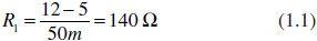
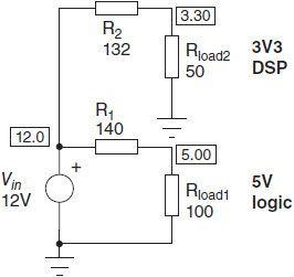
141AssociatingResistors Figure11portraysthesimplestoptionadesignercanthinkof:resistivedividersIfourDSPconsumes66mAover33V,thenitcanbereplaced bya50-Ωresistor,thesameasforour50mA,5-Vlogiccircuitviathe100-ΩresistorFroma12-Vsource,wecanthencalculatethedropping resistors:
FIGURE1.1Thesimplestvoltagedistributionviaresistors
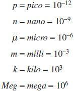
Beforegoingfurther,pleasenotethat0066Aor005Awas,respectively,notedinthecalculationas66mor50m Thisisdonetoretainthe SPICEnotationforunits,withoutanyspaceItadherestothefollowingrulesandwillbeextensivelyusedintheremainingportionsofthebook:
•Bewarenottomixmegaandmilli,averycommonmistake:10mΩ=10m,1MΩ=1Meg
Unfortunately,theseresistorswillbetheseatofapermanentvoltagedrop,andpowerdissipation(inheat)willoccurThedissipatedpowerfor eachresistoris
Fromthesevalues,wecannowevaluatethesystemefficiencyobtainedbydividingthedeliveredoutputpowerPoutbythepowertakenawayfrom thesourcePin:
Theefficiency,representedbytheGreekletterηor“eta,”canbecomputedbydividingPoutbyPin,or whichisanextremelypoorperformance!
Theloss,dissipatedinheat,issimplythedifferencebetweenthepowerdeliveredbythesourceandthepower,convertedastherealwork,Pout. Inourexample,thelossis139–0468=922mW
1.4.2AClosed-LoopSystem
Iftheloadchanges,oriftheinputvoltagedrifts,whatisgoingtohappen?Well,sinceourinput-to-outputtransferratio,denotedM,isfixed,the outputvoltagewillalsovaryTherefore,weneedtothinkofakindofregulatedsystemthatpermanentlyobservestheoutputpowerdemandand adjuststheseriesresistortomaintainaconstantoutputvoltage,iftheoutputvoltagerepresentsthevariableofinterestForawell-designed system,theconvertermustalsoensureaproperregulationindependentofinputvoltagevariationsToreachthisgoal,weneedtouseseveral specificcomponentssuchas
•AreferencevoltageVref:Thisvoltageisbydefinitionextremelystableintemperatureandpreciseinvalue(eg,±1%)Aprogrammableshunt regulator,suchasaTL431adjustableZenerdiode,coulddothejob
•Anoperationalamplifier(opamp):Thisdevicewillobserveaportionoftheoutputvoltage(aVout)andcompareittothereferenceVref Itwill actually“amplify”theerror,thedifferencebetweenaVoutandVref,todriveaseries-passelement.Theerrormonitoredbytheopampisusually denotedbytheGreeklettereor“epsilon”:ε=αVout–Vref
•Aseries-passelement:ItcanbeaMOSFETorabipolartransistorbutworkinginalinearmode,playingtheroleofthenecessaryvariable resistorIfitisaMOSFET,thestaticdrivingpowerisnullForabipolar,thereisaneedtosupplyasufficientamountofbasecurrenttodeliverthe rightcollectororemittercurrent.Thisiscalledthebiascurrent.
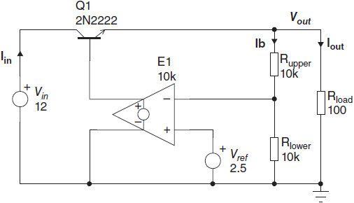
Figure1.2finallyshowshowourresistiveconvertercouldbeimproved,let’ssayforthe5-Vsection.Theerroramplifierismadeviaavoltagecontrolledvoltagesource(Eprimitive)andfeaturesagainof10kor(80dB),20log10(10k)Oneinputreceivesthevoltagereferencewhereasthe otherone,theinvertinginput,isbiasedbyaportionoftheoutputvoltageThisisactuallyalinearregulator,however,limitedintheinputvoltage rangesinceVinshallbeaboveVoutbyaVbe,atleast,toguaranteeaproperdriveforQ1IfVoutisbelowthetarget(5Vinourexample),E1 outputincreasesandstrengthensQ1biascurrent:VoutgoesupOntheotherhand,supposetheloadhassuddenlybeenreduced,thereforeVout exceeds5VThankstoE1,Q1biascurrentgoesdown,reducingtheoutputvoltageuntilregulationismetagain
FIGURE12Theadditionofanerroramplifierbringsregulationtothecircuit:Wehavebuiltalinearregulator
Theoutputvoltageobservation,whichdeliversaVout(afractionoftheoutputvoltage),isobtainedthrougharesistivedividermadeofRupperand Rlower Calculatingtheirvaluesisstraightforward:
1LetusfixacurrentcirculatinginthedividerbridgeSincethereisnobiasingcurrentforE1intheexample(thisisthecaseformostMOS-based technologies),wecouldtakeIb=250μA,forexampleAlowervalueisacceptable,butdegradesthenoiseimmunityinanoisyenvironment
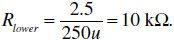
2 Ibequals250μAandentirelycirculatesinRlower Thankstothecontrolloop,25Vis“seen”acrossRlower Therefore,
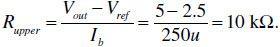
3.ThevoltagedropacrossRupperisVout–Vref.Thus,
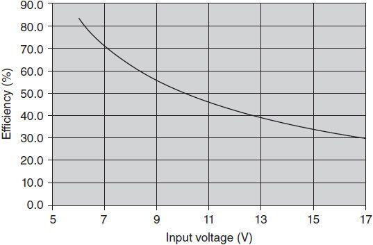
IfweneglectthepowerneededtodriveQ1,thenallthesourcecurrentIinflowsintotheloadasIout.Therefore,applyingEq.(1.7),wecanderive theefficiencyforthislinearregulator:
Ifwenowplottheefficiencyversustheinputvoltage,wecanseehowdifficultthesituationbecomesinthepresenceofsmallMratios(Fig13) Forthesereasons,resistivedividertypeofconverters,thatistosayseries-passregulators,arelimitedtoapplicationswhereMdoesnotfall below03OtherwisetheheatdissipationburdenbecomesarealhandicapOntheotherhand,whentheuserreallyneedstooperatearegulator toratiosMcloserto1(VinveryclosetoVout),thelow-dropout(LDO)regulatormadewithaPNPbecomesagoodchoiceTheinputlowlimitis nowlinkedtothetransistorVce(sat)(afewhundredmillivolts,orless)ratherthanitsVbe(around650mVatroomtemperature,25°C)
AssoonasMdiminishes,theefficiencydramaticallydrops(Vout=5V)
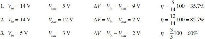
Toclosethestudyonregulatorefficiency,wecantakethreedifferentoutputexampleswithlinearregulators,whereoutputandinputconditions vary:
Asaresult,onecanseethatahighefficiencycanbeobtainedwithalinearregulatorifΔVissmall(asplottedinFig13),butalsoifVout>>ΔV
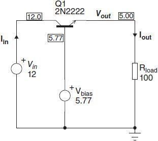
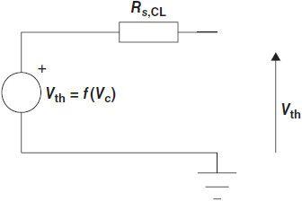
1.4.3DerivingUsefulEquationswiththeLinearRegulator Figure12isinterestingbecausewecanuseittoderivegeneralstatements,pertinenttotheclosed-loopworldwearegoingtoenter,linear,or switchedSupposethatweremovetheerroramplifierandreplaceitbyafixedvoltagesourceof577V,ouractualopampoutput(lookatFig12 values),asFig14showsTheregulatorbecomesasimpleemitter-followercircuit,affectedbyanoutputimpedanceandanoutputvoltageAs such,itcanbedescribedwithitsequivalentThéveningenerator,whatFig.1.5suggests.Rs,OLrepresentstheopen-loopoutputimpedanceand Vth,thevoltagedeliveredwhenbiasedbyacontrolvoltageVc,ourfixed577VintheapplicationLetusnowusethisrepresentationandredraw ourclosed-loopregulatoraroundit,ignoring,fornow,theinputvoltagecontribution
FIGURE14Ifthefeedbackissuppressed,thereisnooutputvoltageobservationtoadjustQ1biaspoint:Wearerunningopen-loop
FIGURE13
FIGURE15AThéveningeneratorportraystheregulatorwhenruninclosedloop
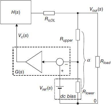
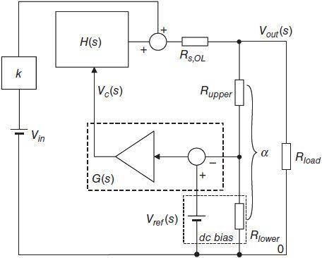
InFig16,Vout(s)iscomparedtoVref(s)viaaresistivedivideraffectedbyatransferratioofa H(0)illustratesthestaticordcrelationship betweentheoutputvoltageandthecontrolvoltageVc,eg,Vc=577VtoobtainVout=5VinthisexampleThetheoreticaldcvoltage(s=0,but wepurposelyavoidedthissubscriptbelowforthesakeofclarity)youwouldexpectfromsuchaconfigurationis
FIGURE1.6Whenclosingtheloop,ourThéveningeneratorundergoesatransformationinitsdynamicbehaviorHere,theinputperturbationis purposelyomitted
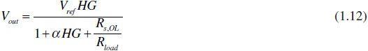
Unfortunately,thewholegainchainandvariousimpedanceswillaffectthisvalueWithafewlinesofalgebra,wecanwritethestaticoutputvoltage definition(again,s=0)simplybyfollowingthemeshes:
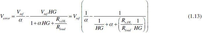
Thestaticerrorontheoutput,actuallythedeviationbetweenwhatwereallywantandwhatwefinallyobtain,isderivedbysubtractingtheVout expressionEq(112)fromEq(110):
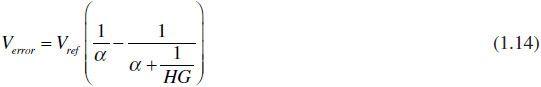
IfweconsiderRs,OL<<Rload,thenEq(113)simplifiesto whichequalszeroif
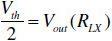
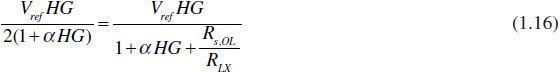
Fromthisequation,wecanseethatincreasingthedcgain,G(0),helpsdiminishthestaticerrorwhichfinallyaffectsouroutputvoltageprecision Anotherimportantparameterinfluencedbytheloopgainistheclosed-loopoutputimpedanceTheoutputimpedanceofasystemcanbederived indifferentmannersAsFig15hasshown,ourclosed-loopgeneratorcannowbereducedtoitsThéveninequivalent,thatis,avoltagesource Vth[Voutmeasuredwithoutanyload,orRload=∞inEq(112)],followedbyanoutputimpedanceRs,CL,whichweactuallylookforOneoption consistsofcalculatingaresistorRLXwhich,oncewiredbetweentheoutputandground,willreduceVout=Vthto Whenthisoccurs, RLXsimplyequalsRs,CL(wehavebuiltasimpleresistivedividerwithequalresistors)WecanquicklymanipulateEq(112),assuming
or“WhatvalueofRLXwilldividetheThéveninvoltageby2?”
IfwecallαHGthestaticloopgainT,thentheclosed-loopoutputimpedanceis
Equation(117)teachesusdifferentthings:
1IfwehavealargedcloopgainT(0),thenRs,CLisclosetozero
2.BecausewehavecompensatedthefeedbackreturnpathG(s)forstabilitypurposes,whentheloopgainT(s)reducesasthefrequency increases,Rs,CLstartstorise:AnimpedancewhosemagnitudegrowswithfrequencylookslikeaninductanceWewillcomebacktothisresult later
3WhentheloopgainT(s)hasdroppedtozero,thesystemexhibitsanoutputimpedancethatisthesameasinthelackoffeedback,Rs,OL:The systemrunsopen-loop
Whydowetalkaboutastatic(dc)andafrequency-dependentgain?Well,thisissosimplybecauseFigs15and16donotrepresentgenuine regulators Inreality,G(s)ismadeviaarealoperationalamplifier,imposingavirtualgroundonitsinvertingpinassoonaslocalfeedback exists Inotherwords,Rlowersimplygoesoffthepictureinthesmall-signalmodel,andanolongerplaysarole ThisisdescribedinApp 3D
Inthisexample,wepurposelydidnotaccountforaninputvoltageperturbationThisassumptionisvalidforbipolartransistorsastheweak influenceoftheEarlyeffectmakesthemgoodcurrentgenerators,almostindependentfromtheirVcevariationsHowever,whenVoutandVinare closetoeachother,thetransistorbecomesaclosedswitchratherthanacurrentsourceTherefore,theinputvoltagestartstoplayaroleLetus redrawtheFig16sketch,includingtheinputvoltagecontributionAsdrawninFig17,thetermkrepresentstheopen-loopaudiosusceptibility, denotedAs,OL Itrepresentstheinputvoltagecontributiontotheoutput
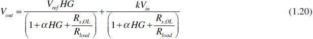
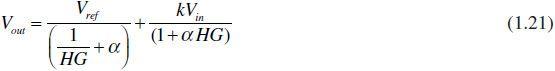
FIGURE1.7OurpreviousregulatormodeisnowupgradedwithaninputperturbationkVin Let’snowwritethemeshequationsaswedidpreviously:
AsEq.(1.21)shows,Voutismadeoftwoterms:
1.Thetheoreticaloutputvoltage,similartowhatwasdefinedinEq(112),simplified,gave(Rload=∞)
2.Theinputvoltagecontributionwhosenewtermis or,stickingtothepreviousdefinition,
Again,operatingwithalargedcgainensuresanexcellentrejectionoftheinputvoltageripple(100or120Hzforfull-waverectification)WhenT(s) reducesinthehigh-frequencydomain,thesystemrunsopen-loop.Pleasenotethatwepurposelyselectedapositivepolarityfork,butanegative valuecouldalsohavebeenchosen.Itactuallydependsonthetopologyunderstudy.
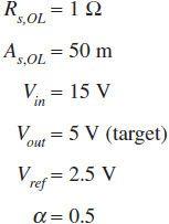
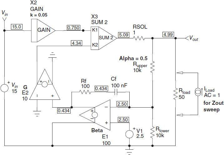
1.4.4APracticalWorkingExample ThankstoSPICE,wecansimulateacompletelytheoreticalregulatorbyassociatingblocksFig18depictsthecircuitwhereyouwillrecognize theblockdiscussedaboveTheoperatingparametersarethefollowing:
FIGURE18Ourtheoreticallinearregulator,includingtheoutputimpedanceandtheinputvoltageperturbation
Pleaseignore,fornow,thepresenceofthecompensationnetworkRf-Cf Applyingouraboveinputnumbersrevealstheseclosed-loopvalues:
Equation(117),Rs,CL=1996mΩ,orindBΩ:20log10(Rs,CL)=20log10(1996m=–54dBΩ
Equation(120),Vout=4991318V
Equation(122),As,CL=998u,orindecibels:20log10(As,Cl)=20log10(998u)=–80dB
Now,letuscomparetowhattheSPICEsimulatorwillgiveWehaveseveraloptionsThefirstoneusesaTFstatement,whichperformsa