ACKNOWLEDGMENTS
The opportunity to publish a 5th edition has far exceeded my expectations for this textbook, and I continue to be amazed by its reception within the radiography community. It takes many dedicated and knowledgeable people to revise and improve a textbook on radiographic imaging and exposure. Sonya Seigafuse has been extraordinarily supportive throughout this journey to publication. Samantha Dalton and William Drone have worked diligently to ensure the quality and accuracy of the chapters.
Educators, students, and radiographers have challenged me to pursue excellence in producing an imaging textbook that is comprehensible, accurate, and relevant to radiographic imaging. I am also indebted to the many authors before me who have explored complex physics concepts in an effort to explain the theory and practice of radiographic imaging. Comprehending the intricacies of digital imaging continues to be a challenge, and I am grateful for the knowledge and expertise of Andrew Woodward in helping me explain complex digital imaging concepts. His contributions have been invaluable. My admiration continues for all the educators, students, and imaging professionals who desire to achieve excellence in radiographic imaging.
Terri L. Fauber
1 Radiation and Its Discovery, 1
2 The X-ray Beam, 15
3 Image Formation and Radiographic Quality, 42
4 Digital Imaging, 67
5 Film-Screen Imaging, 110
6 Exposure Technique Factors, 147
7 Scatter Control, 178
8 Exposure Technique Selection, 208
9 Image Evaluation, 237
10 Dynamic Imaging: Fluoroscopy, 262
Appendix A: Summary of Important Relationships, 285
Appendix B: Summary of Mathematical Applications, 295
Appendix C: Summary of Radiation Protection Alerts, 299
Appendix D: Answer Key for Chapter 9: Image Evaluation, 302
Chapter Review Questions Answer Key, 314
Illustration Credits, 316
Glossary, 318 Index, 324
This page intentionally left blank
CHAPTER OUTLINE
Discovery X-rays as Energy Radiation Units of Measurement
OBJECTIVES
Radiation and Its Discovery
Properties of X-rays The Fundamentals of Radiation Protection
After completing this chapter, the reader will be able to perform the following:
1. Define all the key terms in this chapter.
2. State all the important relationships in this chapter.
3. Describe the events surrounding the discovery of x-rays.
4. Describe the dual nature of x-ray energy.
KEY TERMS
absorbed dose air kerma
5. State the characteristics of electromagnetic radiation.
6. Differentiate among the units of measurement for radiation.
7. List the properties of x-rays.
8. Recognize the fundamentals of radiation protection.
ALARA dose equivalent electromagnetic radiation exposure fluorescence frequency photon quantum radioactivity wavelength
X-rays were discovered in Europe in the late nineteenth century by German scientist Dr.Wilhelm Conrad Roentgen. Although Roentgen discovered x-rays by accident, he proceeded to study them so thoroughly that within a very short time, he identified all the properties of x-rays that are recognized today. Roentgen was more interested in the characteristics of x-rays as a form of energy than their practical application. X-rays are classified as a specific type of energy termed electromagnetic radiation, and like all other types of electromagnetic energy, x-rays act like both waves and particles.
DISCOVERY
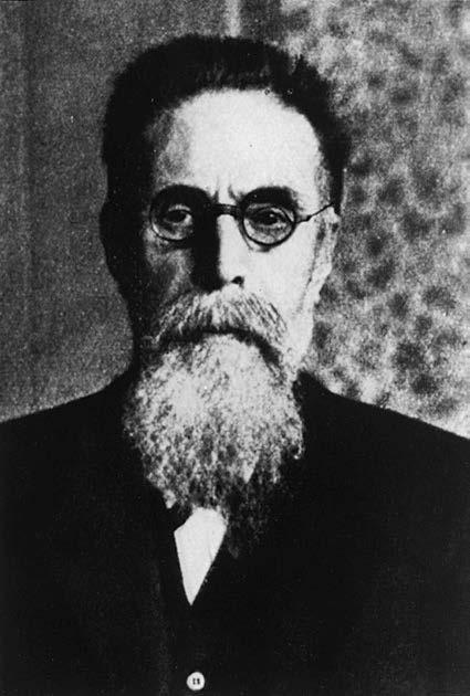
X-rays were discovered on November 8, 1895, by Dr. Wilhelm Conrad Roentgen (Figure 1-1), a German physicist and mathematician. Roentgen studied at the Polytechnic Institute in Zurich. He was appointed to the faculty of the University of Würzburg and was the director of the Physical
Institute at the time of his discovery. As a teacher and researcher, his academic interest was the conduction of high-voltage electricity through a low-vacuum tubes. A low-vacuum tube is simply a glass tube from which a certain amount of air is evacuated. The specific type of tube that Roentgen was working with was called a Crookes tube (Figure 1-2).
At the end of his workday on November 8, Roentgen prepared his research apparatus for the next experimental session to be conducted when he would return to his workplace. He darkened his laboratory to observe the electrical glow (cathode rays) that occurred when the tube was energized. This glow from the tube would indicate that the tube was receiving electricity and was ready for the next experiment. That day, Roentgen covered his tube with black cardboard and again electrified it. By chance, he noticed a faint glow coming from a certain material located several feet from his electrified tube. The source was a piece of paper coated with barium platinocyanide. Not believing that the cathode rays could reach that far from the tube, Roentgen repeated the experiment. Each time Roentgen energized his tube, he observed this glow coming from the barium platinocyanide-coated paper. He concluded that the energy emanating from his tube was causing this paper to produce light, or fluoresce. Fluorescence refers to the instantaneous production of light resulting from the interaction of some type of energy (in this case x-rays) and some element or compound (in this case barium platinocyanide).
Roentgen was understandably excited about this apparent discovery; however, at the same time, he was cautious not to make any early assumptions about what he had observed. Before sharing information about his discovery with colleagues, Roentgen spent time meticulously investigating
FIGURE 1-1 Dr. Wilhelm Conrad Roentgen.
the properties of this new type of energy. Of course, this new type of energy was not new at all; it had always existed and had likely been produced unknowingly by Roentgen and his contemporaries who were also involved in experiments with electricity and low-vacuum tubes. Knowing that others were doing similar research, Roentgen worked in earnest to exactly determine what this energy was.
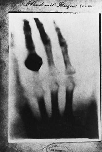
Roentgen spent the next several weeks working feverishly in his laboratory to investigate as many properties of this energy as he could. He noticed that when he placed his hand between his energized tube and the barium platinocyanide-coated paper, he could see the bones of his hand glow on the paper, with this fluoroscopic image moving as he moved his hand. Curious about this, he produced a static image of his wife Anna Bertha’s hand using a 15-min exposure. This became the world’s first radiograph (Figure 1-3). Roentgen gathered other materials and interposed them between his energized tube and the fluorescent paper. Some materials, such as wood, allowed this energy to pass through and caused the paper to fluoresce, whereas some materials, such as platinum, did not.
In December 1895, Roentgen decided that his investigations of this energy were sufficient to inform his physicist colleagues of what he now believed to be a discovery of a new form of energy. He called this energy x-rays, with x representing the mathematical symbol for the unknown. On December 28, 1895, Roentgen submitted a scholarly paper on his research activities to his local professional society, the Würzburg Physico-Medical Society. Written in his native language, German, his article was titled “On a new kind of rays,” and it caused a buzz of excitement in the medical and scientific communities. Within a short time, an English translation of this article appeared in the journal Nature, dated January 23, 1896.
While Roentgen deemed his discovery important, he also considered it to have primarily academic value. His concern was in the x-ray itself as a form of energy and not in its possible practical applications. Others quickly began assembling their own x-ray-producing devices and exposed inanimate objects as well as tissue, both animal and human and both living and dead, to determine the range of use of these x-rays. Their efforts were driven largely by skepticism, rather than belief that x-rays could do what had been claimed. Skepticism eventually gave way to productive curiosity as investigations concentrated on ways of imaging living human bodies for medical benefits. As investigations into legitimate medical applications of the use of x-rays continued, the nonmedical and non-scientific communities began taking a different view of Roentgen’s discovery. X-ray-proof underwear was offered as protection from these rays, which were known to penetrate solid materials, and a New Jersey legislator attempted to enact legislation that would ban the use of x-ray-producing devices in opera glasses. Both these efforts were presumably aimed at
Glass tube
Anode Cathode
Stream of electrons
FIGURE 1-2 A Crookes tube as used by Roentgen to discover x-rays.
protecting an individual’s private anatomy from unscrupulous users of x-rays. The public furor reached such a height that a London newspaper, the Pall Mall Gazette, offered the following editorial in 1896: “We are sick of Roentgen rays. Perhaps the best thing would be for all civilized nations to combine to burn all the Roentgen rays, to execute all the discoverers, and to corner all the equipment in the world and to whelm it in the middle of the ocean. Let the fish contemplate each other’s bones if they like, but not us.”
In a similar vein, but in a more creative fashion, another London periodical, Photography, in 1896 offered the following:
“Roentgen Rays, Roentgen Rays?
What is this craze?
The town’s ablaze
With this new phase
Of x-ray ways.
I’m full of daze, shock and amaze,
For nowadays
I hear they’ll gaze
Through cloak and gown and even stays!
The naughty, naughty Roentgen rays!”
Fortunately, despite these public distractions, the scientific applications of x-rays continued to be investigated for the benefit of society. Roentgen’s discovery was lauded as one of great significance to science and medicine, and Roentgen received the first Nobel Prize presented for physics in 1901. The branch of medicine that was concerned with the use of x-rays was called roentgenology. A unit of radiation exposure was called the roentgen. X-rays were, at one time at least, called roentgen rays.
FIGURE 1-3 The first radiograph that demonstrates the bones of the hand of Roentgen’s wife, Anna Bertha, with a ring on one finger.
Visible
Microwaves
Radiowaves
FIGURE 1-4 Electromagnetic spectrum. Radiowaves are the least energetic on the spectrum, and gamma rays are the most energetic.
Excitement over this previously undiscovered type of energy was tempered by the realization in 1898 that x-rays could cause biological damage. This damage was first noticed as a reddening and burning of the skins (called erythema) of individuals who were exposed to large doses of x-rays required at that time. More serious effects, such as the growth of malignant tumors and chromosomal changes, were attributed in later decades to x-ray exposure. However, despite these disturbing findings, it was realized that x-rays could be used safely. When radiation-protection procedures to safeguard both the radiographer and the patient are followed, x-rays can assist medical diagnosis by imaging virtually every part of the human body.
X-RAYS AS ENERGY
Energy is the ability to do work and it can exist in different forms, such as electrical energy, kinetic energy, thermal energy, and electromagnetic energy. Energy can also be transformed from one form to another; for instance, the electrical energy applied to a stove is changed into heat. Similarly, the electrical energy applied to an x-ray tube is transformed into heat and x-rays.
X-radiations, or x-rays, are a type of electromagnetic radiation. Electromagnetic radiation refers to radiation that has both electrical and magnetic properties. All radiations that are electromagnetic make up a spectrum (Figure 1-4).
In the academic discipline of physics, energy can generally be described as behaving according to the wave or the particle concept of physics. X-rays have a dual nature: they behave like both waves and particles. Higher-energy electromagnetic radiation, such as x-rays, tends to exhibit more particle-like characteristics and lower-energy electromagnetic radiation, such as radiowaves, tend to exhibit more wave-like characteristics.
IMPORTANT RELATIONSHIP
The Dual Nature of X-ray Energy
X-rays act like both waves and particles.
X-rays can be described as waves because they move in waves that have wavelength and frequency. Looking at a sine wave (Figure 1-5), one can see that the wavelength represents the distance between two successive crests or troughs. Wavelength is represented by the Greek letter lambda (λ), and its values are given in units of angstroms (Å). An angstrom is a metric unit of length equal to one ten-billionth of a meter, or 10−10 m. X-rays used in radiography range in wavelength from approximately 0.1 to 1.0 Å. Another unit of measurement for wavelength is nanometer (nm); 1 Å equals 0.1 nm.
The sine wave (Figure 1-5) also demonstrates that frequency represents the number of waves passing a given point per given unit of time. Frequency is represented by a lowercase f or by the Greek letter nu (ν), and its values are given in units of Hertz (Hz). X-rays used in radiography range in frequency from approximately 3 × 10¹⁹ to 3 × 10¹⁸ Hz. Wavelength and frequency are inversely related—that is, as one increases, the other decreases.
IMPORTANT RELATIONSHIP
Wavelength and Frequency
Wavelength and frequency are inversely related. Higher-energy x-rays have decreased wavelength and increased frequency. Lower-energy x-rays have increased wavelength and decreased frequency.
This relationship can be observed in Figure 1-6 and is demonstrated by the expression c = λν, where c represents the speed of light. In this expression, if wavelength increases, frequency must decrease because the speed of light is a constant velocity (3 × 10⁸ m/s or 186,000 miles/s). Conversely, if wavelength decreases, frequency must increase, again because the speed of light is constant. Mathematically, the formulas are λ = c/ν to solve for wavelength and ν = c/λ to solve for frequency.
FIGURE 1-5
Sine wave demonstrating wavelength and frequency. One wavelength is equal to the distance between two successive troughs (points A to B) or the distance between two successive crests (points C to D).
A
Time B
FIGURE 1-6 A, Sine wave demonstrating long wavelength and low frequency. B, Sine wave demonstrating short wavelength and high frequency; Comparison of sine waves. A and B demonstrates the inverse relationship between wavelength and frequency.
X-rays also behave like particles and move as photons or quanta (plural). A photon or quantum (singular) is a small, discrete bundle of energy. For most applications in radiography, x-rays are referred to as photons. When x-rays interact with matter, they behave more like particles than waves. The energy of an individual photon is measured in units of electron volts (eV) and the energy of diagnostic x-rays is approximately between 104 and 105 eV. Decreasing the wavelength and/or increasing the frequency of the x-ray will increase its energy.
Radiation Units of Measurement
It is important to recognize the units of radiation quantity to obtain an accurate understanding of radiation exposure and dose. There are two systems for quantifying radiation exposure: the conventional one and the International System (SI). SI has become the more widely adopted of the two. Radiation exposure can be measured in the following units:
Unit of Measure
Conventional International System (SI)
Exposure roentgen (R) air kerma (Gy)
Absorbed Dose radiation absorbed dose (rad) gray (Gy)
Dose Equivalent radiation equivalent in man (rem) sievert (Sv)
Radioactivity curie (Ci) becquerel (Bq)
Exposure
The quantity of radiation exposure expressed in roentgens (R) measures the amount of ionization or electrical charge in a specified amount of air; this is a measure of the intensity of radiation exposure. Air kerma is the amount of energy deposited in a unit mass of air and expressed in units of gray (Gy). Radiation exposure is typically expressed in smaller units by adding the prefix “milli,” where 1 R = 1000 mR and 1 Gy = 1000 mGy.
Absorbed Dose
The rad and gray are units measuring the transfer of radiation energy into matter (e.g., tissue), known as the absorbed dose. One rad equals a transfer of 100 ergs per gram of any absorbing matter. One gray (Gy) is defined as 1 joule of energy absorbed in each kilogram of absorbing material. One gray equals 100 rads. A conversion factor of 0.01 is used to convert rads into grays. For example, an absorbed dose of 5 rads = 0.05 Gy.
Absorbed dose is typically used in referring to patient exposure and is expressed as millirads or mGy because of the low level of radiation-absorbed dose that occurs during medical procedures. The amount of absorbed dose is dependent on the energy of the ionizing radiation and the type of interacting tissues.
Dose Equivalent
The units used in measuring occupational radiation exposure (dose equivalent) are radiation equivalents in man (rem) and sieverts (Sv). One sievert equals 100 rem. These units are derived by multiplying a quality factor by the units of absorbed exposure, rads or grays. The quality factor takes into consideration the biological effects of different types of ionizing radiation. X- and gamma rays have a quality factor of 1 and therefore are equal in their biological effect on tissues. Consequently, 1 rad or 0.01 Gy is equal to 1 rem or 0.01 Sv. Differing particulate radiations have associated quality factors, resulting in changes in the biologic effects following exposure.
Radioactivity
Unstable atoms will spontaneously emit particles and energy from the nucleus in an effort to reach stability (radioactivity). This process is called radioactive disintegration or decay. Radioisotopes are the radioactive elements used in nuclear medicine and radiation therapy.
The curie and the becquerel measure the rate of nuclear disintegration or decay of a material. Radioactive disintegration or decay refers to the decrease in the activity of a radiation source. Half-life is a term that describes the time it takes for the radiation activity to reduce to 50% of its original activity.
PROPERTIES OF X-RAYS
X-rays are known to have several characteristics or properties. These characteristics are briefly explained here and presented in Box 1-1.
• X-rays are invisible. In addition to being unable to see x-rays, one cannot feel, smell, or hear them.
• X-rays are electrically neutral. X-rays have neither a positive nor a negative charge; they cannot be accelerated or made to change direction by a magnet or electrical field.
• X-rays have no mass. X-rays create no resistance to being put into motion and cannot produce force.
• X-rays travel at the speed of light in a vacuum. X-rays move at a constant velocity of 3 × 10⁸ m/s or 186,000 miles/s in a vacuum.
• X-rays cannot be optically focused. Optical lenses have no ability to focus or refract x-ray photons.
• X-rays form polyenergetic or heterogeneous beams. The x-ray beam that is used in diagnostic radiography is composed of photons that have many different energies. The maximum energy that a photon in any beam may have is expressed by the kilovoltage peak (kVp), which is set on the control panel of the radiographic unit by the radiographer.
• X-rays can be produced in a range of energies. These are useful for different purposes in diagnostic radiography. The medically useful diagnostic range of x-ray energies is 30–150 kVp.
• X-rays travel in straight lines. X-rays used in diagnostic radiography form a divergent beam in which each individual photon travels in a straight line.
• X-rays can cause certain substances to fluoresce. When x-rays strike certain substances, those substances produce light. These substances are used in diagnostic radiography, such as image receptors.
• X-rays cause chemical changes to occur in radiographic and photographic films. X-rays are capable of causing images to appear on radiographic film and are capable of fogging photographic film.
BOX 1-1 Characteristics of X-rays
Are invisible
Are electrically neutral
Have no mass
Travel at the speed of light in a vacuum
Cannot be optically focused
Form a polyenergetic or heterogeneous beam
Can be produced in a range of energies
Travel in straight lines
Can cause some substances to fluoresce
Cause chemical changes in radiographic and photographic film
Can penetrate the human body
Can be absorbed or scattered in the human body
Can produce secondary radiation
Can cause damage to living tissue
• X-rays can penetrate the human body. X-rays have the ability to pass through the body based on the energy of the x-rays and on the compositions and thicknesses of the tissues being exposed.
• X-rays can be absorbed or scattered by tissues in the human body. Depending on the energy of an individual x-ray photon, that photon may be absorbed in the body or made to scatter, moving in another direction.
• X-rays can produce secondary radiation. When x-rays are absorbed as a result of a specific type of interaction with matter (photoelectric effect), a secondary or characteristic photon is produced.
• X-rays can cause chemical and biologic damage to living tissue. Through excitation and ionization (removal of electrons) of atoms comprising cells, damage to the cells can occur.
THE FUNDAMENTALS OF RADIATION PROTECTION
A central message throughout this textbook is that it is the radiographer’s responsibility to minimize the radiation dose to the patient, to themselves, and to others in accordance with the As Low As Reasonably Achievable (ALARA) Principle.
Radiation Protection Alert ALARA Principle
It is the radiographer’s responsibility to minimize the radiation dose to the patient, to themselves, and to others in accordance with the As Low As Reasonably Achievable (ALARA) Principle.
Central to minimizing the radiation dose to oneself and to others are the cardinal principles of shielding, time, and distance. Shielding broadly refers to the use of radiopaque materials (i.e., materials through which x-rays do NOT pass easily) to greatly reduce radiation exposure to areas of the patient not essential for the exam being performed, to radiographers during exams, and to others. Lead-impregnated materials are a common example. Leaded/rubber sheets of varying sizes may be directly laid on the patient to shield radiosensitive areas. One example of this
is gonadal shielding; these are specifically shaped lead materials that are placed directly over the gonadal area to minimize radiation dose to these radiosensitive areas. They must be carefully and precisely placed to prevent interference with the image and the anatomic area of interest. They should be used on all patients within reproductive age and when it will not interfere with the primary imaging objective of the examination being performed. Lead aprons may be worn by the radiographer or other health care workers when it is necessary to be in close proximity to the patient during an exposure. In addition, thyroid shields are commonly used in conjunction with lead aprons during fluoroscopic exams by those personnel that remain in the room. This collar wraps around the neck and fastens in the back to shield the entire front portion of the neck. Leaded curtains may be draped from the fluoroscopy tower to provide a barrier between the fluoroscopist and the x-ray beam during fluoroscopic exams. The walls of the radiographic suite provide lead or lead equivalent (thicknesses of other materials that provide equivalent radiopaque properties as lead) to limit exposure beyond that intended for the radiological exam. The primary barriers are those to which the x-ray beam is routinely directed, such as the floor beneath the x-ray table and the wall behind the upright Bucky. Secondary barriers are the others, such as the wall separating the control panel from the room and the ceiling. The general rule of thumb is to always maximize shielding (use as much as possible).
Time broadly refers to the duration of exposure to ionizing radiation and the time spent in a health care environment where exposure to ionizing radiation is accumulated. This may include the length exposure and number of times the patient is exposed for a radiological exam or the time a radiographer spends in a fluoroscopy suite (or any procedure involving fluoroscopy). Whether one is referring to the patient, to the radiographer, or to other health care workers, the general rule of thumb is to always minimize time (limit duration of exposure to ionizing radiation).
Distance refers to the space between oneself and the source of ionizing radiation. This is an effective means of limiting exposure simply because the intensity (quantity) of radiation diminishes over distance. This is an application of the inverse-square law discussed in detail in Chapter 6. Suffice it to say here that as one increases the distance from an ionizing radiation source, the intensity of that source significantly decreases. This principle is applied mostly to radiographers and others to maintain a safe distance from the source of radiation during exposure. The general rule of thumb is always to maximize distance (maintain a safe distance from the radiation source during exposure).
Radiation Protection Alert
Cardinal Principles for Minimizing Radiation Dose
Time- Limit the amount of time exposed to ionizing radiation
Distance- Maintain a safe distance from source of ionizing radiation exposure
Shielding- Maximize the use of shielding from ionizing radiation exposure
Another important tool in radiation protection is the limiting of the field of x-ray exposure, essentially beam restriction, through the use of a collimator. By limiting the area of exposure, this device limits the radiation dose to the patient; that is, the smaller the area of x-ray exposure, the lower the total dose to the patient. When we discuss radiation interactions in the body, we are talking about x-ray photons interacting with atoms of tissue. The greater the volume of tissue we expose, the greater the opportunity for such interactions to occur. With these interactions, the photon’s energy will either be totally absorbed (which contributes to patient dose) or scattered (which may contribute to the dose to radiographers or others if in the immediate area). See Chapter 3 for a full discussion of x-ray interactions with matter.
Radiation Protection Alert
Beam Restriction
Limiting the size of the x-ray exposure field reduces the volume of tissue irradiated and limits the radiation dose to the patient.
Next among our “tools” of radiation protection are the primary controls of the x-ray beam’s kilovoltage peak (kVp), milliamperage (mA), and duration (s), mAs = mA × s. These are the factors selected by the radiographer to produce an x-ray beam of a given quality (penetrating power), controlled by kVp, and quantity (number of photons), ultimately controlled by mAs. The combination of kVp and mAs is selected on the basis of a number of considerations including the anatomic part being examined, patient age, condition, pathology, etc. and should be ideally suited to the circumstance to minimize radiation dose while producing a quality image. See Chapter 6 for a complete discussion of these factors.
Radiation Protection Alert
Primary Exposure Factors
The combination of kVp and mAs is selected based on a number of considerations, including the anatomic part being examined, patient age, condition, and pathology, and should be ideally suited to the circumstance to minimize radiation dose while producing a quality image.
Finally, there are a number of daily “work flow” tasks and processes that address radiation protection. A major one, for which the radiographer serves as a front line advocate for the patient, is the avoidance of duplication of exams. This means preventing the patient from having the same exam performed twice owing to an error. With so much computerization, automation, and team approach to patient care, it is easy to duplicate an order (accidentally order the same radiographic exam more than once) or for two different physicians involved in a patient’s care to unknowingly order the same thing. There are instances where a patient’s condition rapidly changes and it is necessary to perform the same exam a number of times in succession; but it is okay to doublecheck an order or to stop and question. The radiographer must recognize and accept his/her role as a patient advocate and do what is necessary to avoid unnecessary duplication of exams. Think of each duplicate exam as a doubling of the radiation dose that is otherwise needed (the first exam was a normal dose, and the unnecessary one doubles that dose). Thus, this radiation protection measure alone significantly impacts the radiation dose administered to the patient and to others.

Radiation Protection Alert
Avoid Duplicate Exams
The radiographer must recognize and accept his/her role as a patient advocate and do what is necessary to avoid duplication of exams.
Screening for pregnancy is another important task for minimizing unnecessary exposure to a developing fetus. Departmental protocols for pregnancy screening may vary and should be consistently employed. When it is necessary to perform a radiographic exam on a pregnant patient, shielding materials and precise collimation, as discussed previously, should be used to minimize radiation dose administered to the fetus. Be sure to follow the clinical site policy for pregnancy screening.
Radiation Protection Alert Screening for Pregnancy
Screening for pregnancy is another important task for minimizing unnecessary exposure to a developing fetus. When it is necessary to perform a radiographic exam on a pregnant patient, shielding materials and precise collimation should be used to minimize the radiation dose administered to the fetus.
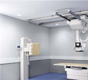
Lastly, as a developing radiographer, good work habits and skills have not yet been developed. Use sufficient time and concentration to “get it right the first time.” Develop a mental checklist for radiographic procedures and perform them the same way every time. By doing so, mistakes involving the details of a task can be minimized along with unnecessary radiation dose administered to the patient and to others. See Box 1-2 for a summary of radiation protection fundamentals. Since the publication of Roentgen’s scientific paper, no other properties of x-rays have been discovered. However, the discussion of x-rays has expanded far beyond the early concerns about modesty or even danger. Today, x-rays are accepted as an important diagnostic tool in medicine, and the radiographer is an important member of the health care team. The radiographic imaging professional is responsible for the care of the patient in the radiology department, the production and control of x-rays, and the formation of the radiographic image. Figure 1-7 shows a standard
BOX 1-2 Summary of Radiation Protection Fundamentals
• Minimize the radiation dose to the patient, to themselves, and to others in accordance with the As Low AS Reasonably Achievable (ALARA) Principle
• Limit the amount of time exposed to ionizing radiation
• Maintain a safe distance from source of ionizing radiation exposure
• Maximize the use of shielding from ionizing radiation exposure
• Limit the size of the x-ray exposure field to the area of interest
• Select a combination of kVp and mAs to produce a diagnostic image while minimizing patient radiation exposure
• Avoid unnecessary duplicate exams
• Screen for pregnancy
• Develop a mental checklist for radiographic procedures and perform consistently
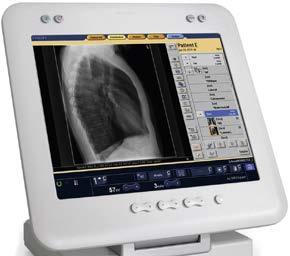
FIGURE 1-7 A, Typical radiographic unit showing the x-ray table, overhead x-ray tube, and collimator. B, Control panel.
radiographic room that includes an x-ray table, overhead x-ray tube and collimator, and a control panel for the selection of exposure technique factors. The subsequent chapters of this book uncover the intricate and fascinating details of the art and science of medical radiography.
CHAPTER SUMMARY
• X-rays were discovered on November 8, 1895, by Dr. Wilhelm Conrad Roentgen, a German physicist, mathematician, and recipient of the first Nobel Prize for physics.
• The discovery of x-rays was met with skepticism and curiosity and subsequently by acceptance of its medical benefit.
• X-rays are a type of electromagnetic radiation with both electrical and magnetic properties.
• Electromagnetic radiation is a form of energy that moves in waves with wavelength and frequency.
• Wavelength and frequency are inversely related. Higher-energy x-rays have decreased wavelength and increased frequency.
• X-rays act like both waves and particles and have a higher energy than other types of electromagnetic radiation, such as visible light.
• There are two systems of quantifying radiation exposure: the conventional system and the International System (SI). Exposure in air - roentgen (R) and air kerma; Absorbed Doseradiation absorbed dose (rad) and gray (Gy); Dose Equivalent - radiation equivalent in man (rem) and sievert (Sv); Radioactivity - curie (Ci) and becquerel (Bq).
• X-rays have several important characteristics: they are invisible and electrically neutral, have no mass, travel at the speed of light, penetrate matter, and can cause chemical and biologic changes.
• The fundamentals of radiation protection include adhering to the ALARA principle, time, distance, shielding, beam restriction, careful selection of exposure technique factors, avoidance of duplicate exams, and screening for pregnancy.
REVIEW QUESTIONS
1. In what year were x-rays discovered?
A. 1892
B. 1895
C. 1898
D. 1901
2. In what year were some of the biologically damaging effects of x-rays discovered?
A. 1892
B. 1895
C. 1898
D. 1901
3. X-rays were discovered in experiments dealing with electricity and ___________.
A. ionization
B. magnetism
C. atomic structure
D. vacuum tubes
4. X-rays were discovered when they caused a barium platinocyanide-coated plate to _________.
A. fluoresce
B. phosphoresce
C. vibrate
D. burn and redden
5. X-radiation is classified in which spectrum?
A. Radiation
B. Energy
C. Atomic
D. Electromagnetic
6. X-rays have a dual nature, which means that they behave like both ________________.
A. atoms and molecules
B. photons and quanta
C. waves and particles
D. charged and uncharged particles
7. The wavelength and frequency of x-rays are __________________ related.
A. directly
B. inversely
C. partially
D. not
8. X-rays have __________________ electrical charge.
A. a positive
B. a negative
C. an alternately positive and negative
D. no
9. X-rays have ____________.
A. no mass
B. the same mass as electrons
C. the same mass as protons
D. the same mass as neutrons
10. The x-ray beam used in diagnostic radiography can be described as being ___________.
A. homogeneous
B. monoenergetic
C. polyenergetic
D. scattered
11. The unit that measures the transfer of radiation energy into tissues is known as the ___________.
A. roentgen
B. REM
C. gray
D. sievert
12. Which of the following will minimize radiation exposure to the patient?
A. Beam restriction
B. Gonadal shielding
C. Screening for pregnancy
D. All of the above
The X-ray Beam
CHAPTER OUTLINE
X-ray Production
Cathode
Anode
X-ray Tube Housing
Target Interactions
Bremsstrahlung Interactions
Characteristic Interactions
OBJECTIVES
X-ray Emission Spectrum
X-ray Exposure
X-ray Quality and Quantity
Kilovoltage
Milliamperage
Exposure Time
Milliamperage and Time
Line-focus Principle
Anode Heel Effect
Beam Filtration
Compensating Filters
Heat Units
Extending X-ray Tube Life
After completing this chapter, the reader will be able to perform the following:
1. Define all the key terms in this chapter.
2. State all the important relationships in this chapter.
3. Describe the construction of an x-ray tube.
4. State the function of each component of an x-ray tube.
5. Describe how x-rays are produced.
6. Explain the role of the primary exposure factors in determining the quality and quantity of x-rays.
7. Explain the line-focus principle.
KEY TERMS
actual focal spot size
added filtration
anode
anode heel effect
bremsstrahlung interactions
cathode
characteristic interactions
compensating filter dosimeter
effective focal spot size
exposure time
filament
filament current focusing cup
8. State how the anode heel effect can be used in radiography.
9. Differentiate among the types of filtration and explain their purpose.
10. Calculate heat units.
11. Recognize how changing generator output, kVp, mA, and filtration affect the x-ray emission spectrum.
12. List the guidelines followed to extend the life of an x-ray tube.
half-value layer (HVL)
heat unit (HU)
inherent filtration
kilovoltage
leakage radiation
line-focus principle
milliamperage
off-focus radiation
rotor
space charge
space charge effect
stator
target
thermionic emission
total filtration
trough filter
tube current
voltage ripple
wedge filter
x-ray emission spectrum
The x-ray tube is the most important part of the x-ray machine because the tube is where the x-rays are produced. Radiographers must understand the construction and operation of an x-ray tube. The radiographer controls many actions that occur within the tube. Kilovoltage peak (kVp), milliamperage (mA), and exposure time all are factors that the radiographer adjusts on the control panel to produce a quality image. The radiographer also needs to be aware of the amount of heat produced during x-ray production because excessive heat can damage the tube.
X-RAY PRODUCTION
The production of x-rays requires a rapidly moving stream of electrons that are suddenly decelerated or stopped. The source of electrons is a cathode, or negative electrode. The negative electrode is heated and electrons are emitted. The electrons are attracted to the positively charged anode (positive electrode) and move rapidly toward the anode where they are stopped or decelerated. When the kinetic energy of the electrons is transferred to the anode, x-rays and heat are produced.
Cathode
The cathode of an x-ray tube is a negatively charged electrode. It comprises a filament and a focusing cup. Figure 2-1 shows a double-filament cathode surrounded by a focusing cup. The filament is a coiled tungsten wire, which is the source of electrons during x-ray production.
IMPORTANT RELATIONSHIP
Filament
The filament is the source of electrons during x-ray production.
Most x-ray tubes are referred to as dual-focus tubes because they have two filaments: one large and one small. Only one filament is energized at any one time during x-ray production. If the radiographer selects a large focal spot when setting the control panel, the large filament is energized. If a small focal spot is chosen, the small filament is energized. The focusing cup is made of nickel and nearly surrounds the filament. It is open at one end to allow electrons to flow freely across the tube from cathode to anode. It has a negative charge, which keeps the cloud of electrons emitted from the filament from spreading apart. Its purpose is to focus the stream of electrons.
filament for large focal spot
filament for small focal spot
FIGURE 2-1 Most x-ray tubes use a small filament and a large filament, corresponding to a small focal spot size and a large focal spot size.
Wire
Wire
Focusing cup
Cathode
Anode
The anode of an x-ray tube is a positively charged electrode composed of molybdenum, copper, tungsten, and graphite. These materials are used for their thermal and electrical conductive properties. The anode consists of a target and, in rotating anode tubes, a stator and rotor. The target is a metal that abruptly decelerates and stops electrons in the tube current, allowing the production of x-rays. The target can be either rotating or stationary. Tubes with rotating targets are more common than tubes with stationary ones. Rotating anodes are manufactured to rotate at a set speed ranging from 3000 to 10,000 revolutions per minute (rpm). Figure 2-2 shows how a rotating anode and stationary anode differ in appearance.
IMPORTANT RELATIONSHIP
Target
The target is the part of the anode that is struck by the focused stream of electrons coming from the cathode. The target stops the electrons and creates the opportunity for the production of x-rays.
The target of the rotating anode tubes is made of a tungsten and rhenium alloy. This layer, or track, is embedded in a base of molybdenum and graphite (Figure 2-3 ). Tungsten generally constitutes 90% of the composition of the rotating target, with rhenium constituting the other 10%. The face of the anode is angled to help the x-ray photons exit the tube. Rotating targets generally have a target angle ranging from 5° to 20°. Tungsten is used for both rotating and stationary targets because it has a high atomic number of 74 for efficient x-ray production and a high melting point of 3400°C (6152°F). Most of the energy produced by an x-ray tube is heat; thus, melting of the target can sometimes become a problem, especially with high exposures.
A B
FIGURE 2-2 Side views of a stationary anode (A) and a rotating anode (B).
Tungstenrhenium alloy
Molybdenum
Graphite
FIGURE 2-3 Typical construction of a rotating anode.
Stator Anode stem Anode
Tungsten/rhenium anode disk
FIGURE 2-4
Structure of a typical x-ray tube, including the major operational parts.
IMPORTANT RELATIONSHIP
Tungsten
Because tungsten has a high atomic number (74) and a high melting point (3,400°C [6,152°F]), it efficiently produces x-rays.
In order to turn the anode during x-ray production, a rotating anode tube requires a stator and rotor (Figure 2-4). The stator is an electric motor that turns the rotor at very high speed. The rotor (made of copper) is rigidly connected to the target through the anode stem (made of molybdenum), causing the target to rapidly rotate during x-ray production. High-strength ball bearings in the rotor allow it to smoothly rotate at high speeds.
During x-ray production, most of the energy produced at the anode is heat, with a very small percentage being x-ray energy. Heat can pose a problem if allowed to build up; hence, it is transferred to the envelope and then to the insulating oil surrounding the tube. Moreover, many tube assemblies have a fan that blows air over the tube to help dissipate heat.
IMPORTANT RELATIONSHIP
Dissipating Heat
The heat produced when the x-ray exposure is activated is transferred to the insulating oil that surrounds the x-ray tube.
Rotating anodes can withstand high heat loads; this ability relates to the actual focal spot, which is the physical area of the target that is bombarded by electrons during x-ray production. With stationary targets, the focal spot is a fixed area on the surface of the target. With rotating targets, this area is represented by a focal track. Figure 2-5 shows the stationary anode’s focal spot and the rotating anode with its focal track. The size of the focal spot is not altered with a rotating anode, but the actual physical area of the target bombarded by electrons is constantly changing, causing a greater area—a focal track—to be exposed to electrons. Because of the larger area of the target being bombarded during an exposure, the rotating anode is able to withstand higher heat loads produced by greater exposure factors. Rotating anode x-ray tubes are used in all applications in radiography, whereas stationary anode tubes are limited to studies of small anatomic structures such as teeth.
Port Glass envelope
Filament in focusing cup
Rotor
FIGURE 2-5 A, Front view of a stationary anode. B, The target area of the rotating anode turns during exposure along with an increased physical area—a focal track—that is exposed to electrons.
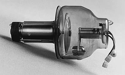
2-6 A glass envelope x-ray tube as it appears before installation in a tube housing.
IMPORTANT RELATIONSHIP
Rotating anodes can withstand higher heat loads than stationary anodes because the rotation causes a greater physical area, or focal track, to be exposed to electrons.
X-ray Tube Housing
The components necessary for x-ray production are housed in a glass or metal envelope. Figure 2-6 shows the appearance of a glass x-ray tube. Metal envelopes are more commonly used because of their superior electrical properties.
A disadvantage of a glass envelope x-ray tube is that tungsten evaporated from the filament during exposure can be deposited upon the inside of the glass, especially in the middle portion of the envelope. This evaporation can affect the flow of electrons and cause the tube to fail. Replacing this section of glass with metal prevents these problems and extends the tube life. An additional
FIGURE
advantage of a metal envelope is the reduction of off-focus radiation. Off-focus radiation occurs when projectile electrons are reflected and x-rays are produced from outside the focal spot. The metal tube envelope can collect these electrons and conduct them away from the anode.
The envelope allows air to be completely evacuated from the x-ray tube, which in turn allows an efficient flow of electrons from cathode to anode. The envelope serves two additional functions: it provides some insulation from electrical shock that may occur because the cathode and anode contain electrical charges and it dissipates heat in the tube by conducting it to the insulating oil surrounding the envelope. The purpose of insulating oil is to provide more insulation from electrical shock and to help dissipate heat away from the tube. All of these components are surrounded by metal tube housing on all sides except for a port, or window, which allows the primary beam to exit the tube. It is the metal tube housing that the radiographer observes and handles when moving the x-ray tube. The tube housing is lined with lead to provide additional shielding from leakage radiation. Leakage radiation refers to any x-rays, other than the primary beam, that escape the tube housing. The tube housing is required to allow a leakage radiation of no more than 100 mR/hr to escape when measured at a distance of 1 m from the source while the tube operates at maximum output. Electrical current is supplied to the x-ray tube using two high-voltage cables that enter the top of the tube assembly.
TARGET INTERACTIONS
The electrons that move from the cathode to the anode travel extremely fast, approximately at half the speed of light. The moving electrons, which have kinetic energy, strike the target and interact with the tungsten atoms in the anode to produce x-rays.
IMPORTANT RELATIONSHIP
Production of X-rays
As electrons strike the target, their kinetic energy is transferred to the tungsten atoms in the anode to produce x-rays.
These interactions occur within the top 0.5 mm of the anode surface. Two types of interactions produce x-ray photons: bremsstrahlung interactions and characteristic interactions.
IMPORTANT RELATIONSHIP
Interactions that Produce X-ray Photons
Bremsstrahlung interactions and characteristic interactions both produce x-ray photons.
Bremsstrahlung Interactions
Bremsstrahlung is a German word meaning “braking” or “slowing down radiation.” Bremsstrahlung interactions occur when a projectile electron completely avoids the orbital electrons of a tungsten atom and travels very close to its nucleus. The very strong electrostatic force of the nucleus causes the electron to suddenly “slow down.” As the electron loses energy, it suddenly changes its direction, and the energy loss then reappears as an x-ray photon (Figure 2-7). In the diagnostic energy range from 30 to 150 kVp, most x-ray interactions are bremsstrahlung. Below 70 kVp (with a tungsten target), 100% of the x-ray beam results from bremsstrahlung interactions. Above 70 kVp, approximately 85% of the beam results from bremsstrahlung interactions.
High-energy bremsstrahlung x-ray photon
Low-energy bremsstrahlung x-ray photon
IMPORTANT RELATIONSHIP
Bremsstrahlung Interactions
Most x-ray interactions in the diagnostic energy range are bremsstrahlung.
Characteristic Interactions
Characteristic interactions are produced when a projectile electron interacts with an electron from the inner shell (K-shell) of a tungsten atom. The electron must have enough energy to eject the K-shell electron from its orbit. K-shell electrons in tungsten have the strongest binding energy at 69.5 keV. For a projectile electron to remove this orbital electron, it must possess energy equal to or greater than 69.5 keV. When the K-shell electron is ejected from its orbit, an outer-shell electron drops into the open position and creates an energy difference. The energy difference is emitted as an x-ray photon (Figure 2-8). Electrons from the L-, M-, O-, and P-shells of the tungsten atom are also ejected from their orbits. However, the photons created from these interactions have very low energy and, depending on filtration, may not even reach the patient. K-shell characteristic x-rays have an average energy of approximately 69 keV; therefore, they significantly contribute to the useful x-ray beams. Below 70 kVp (with a tungsten target), no characteristic x-rays are present in the beam; above 70 kVp, approximately 15% of the beam consists of characteristic x-rays. X-rays produced through these interactions are termed characteristic x-rays because their energies are characteristic of the tungsten target element.
FIGURE 2-7 Bremsstrahlung interaction.