This textbook serves as a practical image analysis and procedure reference for radiography educators, students, and technologists by providing information to correlate the technical and positioning procedures with the image analysis guidelines for common projections; adjust the procedural setup for patient condition variations, for nonroutine situations, and when a less-than-optimal projection is obtained; develop a high degree of radiography problem-solving ability; and prepare for the radiography ARRT examination.
THIS EDITION
The organization of the procedures for this edition has continued with the changes introduced in the last edition to reduce repeatable information and provide efficient access to specific data. The new format includes additional quick, accessible tables that summarize important details and can be used for easy reference. This edition also includes many new and updated projections with improved resolution. Chapters 1 and 2 lay the foundation for evaluating all projections, outlining the technical and digital imaging
concepts that are to be considered when studying the procedures presented in the subsequent chapters. Chapters 3 through 12 detail the image analysis guidelines for commonly performed radiographic procedures. For each procedure presented, this edition provides the following:
• Accurately positioned projections with labeled anatomy.
• Photographs of accurately positioned models.
• Tables that provide a detailed one-to-one correlation between the positioning procedures and the image analysis guidelines.
• Discussions, with correlating projections, on identifying how the patient, central ray, or image receptor was poorly positioned if the projection does not demonstrate an image analysis guideline.
• Discussions of topics relating to positioning for patient condition variations and nonroutine situations.
• Illustrations and photographs of bones and models, positioned to clarify information and demonstrate anatomy alignment when distortion makes it difficult.
• Practice projections that demonstrate common procedural errors.
ACKNOWLEDGMENTS
I would like to thank the following individuals who have helped with this edition.
The University of Iowa Hospitals and Clinics’ Radiologic Technology Classes of 1988 to 2019, who have been my best teachers because they have challenged me with their questions and insights.
Sonya Seigafuse, Luke Held, Kathleen Nahm, and the entire Elsevier team for their support, assistance, and expertise in planning and developing this project.
The professional colleagues, book reviewers, educators, and technologists who have evaluated the book, sent me compliments and suggestions, and questioned concepts in the previous editions.
Kathy
OUTLINE
Why Image Analysis, 2
Terminology, 3
Characteristics of the Optimal Projection, 3
Image Analysis Process, 4
1. Demographic Requirements Are Visualized on the Projection, 6
2. Projection Is Accurately Displayed on the Workstation Screen, 6
OBJECTIVES
Guidelines for Image Analysis 1 CHAPTER
3. Correct Marker Is Visualized on Projection and Demonstrates Accurate Placement, 8
4. Appropriate Collimation Practices Are Evident, 12
5. Relationships Between the Anatomic Structures Are Accurate for the Projection Demonstrated, 12
After completion of this chapter, you should be able to do the following:
• State the characteristics of an optimal projection.
• Properly display projections of all body structures.
• State how the patient is associated with the projections and explain what to do if there is a misassociation.
• Discuss how to mark projections accurately and explain the procedure to be followed if a projection has been mismarked or the marker is only faintly seen.
• Discuss why good collimation practices are necessary and list the guidelines to follow to ensure good collimation.
• Describe how positioning of anatomic structures in reference to the central ray (CR) and image receptor
KEY TERMS
ALARA annotation anterior backup timer contrast mask decubitus detector element (DEL) distortion dose creep dose equivalent limit double exposure elongation exposure maintenance formula field of view (FOV) flexion focal spot foreshortening
6. Projection Demonstrates Maximum Spatial Resolution, 28
7. Radiation Protection Is Present on Projection When Indicated, and Good Radiation Protection Practices Are Used During the Procedure, 29
(IR) affects how they are visualized on the resulting projection.
• State how similarly appearing structures can be identified on projections.
• Determine the amount of patient or CR adjustment required when poorly positioned projections are obtained.
• Discuss the factors that affect the spatial resolution in a projection.
• Describe the radiation protection practices that are followed to limit patient and personnel dose and discuss how to identify whether adequate shielding was used.
geometric factors grid grid cutoff image receptor (IR) inverse square law involuntary motion lateral magnification formula matrix medial midcoronal plane midsagittal plane motion unsharpness nonstochastic effects object–image receptor distance (OID) picture archival and communication system (PACS)
pixel posterior profile project radiolucent radiopaque recorded detail
spatial resolution stochastic effects values of interest (VOI) voluntary motion
WHY IMAGE ANALYSIS?
Radiographic projections are such that slight differences in quality do not necessarily rule out their diagnostic value. Reviewers can ordinarily make satisfactory adjustments by reason of their experience and knowledge, although passing less than optimal projections may compromise the diagnosis and treatment and result in additional projections at a higher expense and radiation dose to the patient. The purpose of image analysis is to explore how to evaluate projections for acceptability, determine how to improve positioning and technical skills before repeating a projection, and continually improve skills.
Why does a technologist care about creating optimal projections and studying all the small details relating to image analysis? The most important answer to this question lies in why most technologists join the profession—to help people. From the patient’s point of view, it provides the reviewer with projections that contain optimal diagnostic value, prevents the anxiety that occurs when additional projections or studies need to be performed, and prevents the radiation dosage that might be caused by additional imaging. From a societal point of view, it helps to prevent additional increases in health care costs that could result because of the need for additional, more expensive imaging procedures and because of the malpractice cases that might result from a poor or missed diagnosis. From a technologist’s point of view, it would be the preventable financial burden and stress that arise from legal actions, a means of protecting professional interest as more diagnostic procedures are being replaced with other modalities, and the personal satisfaction gained when our patients, employer, and ourselves benefit from and are recognized for our expertise.
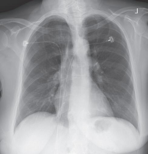
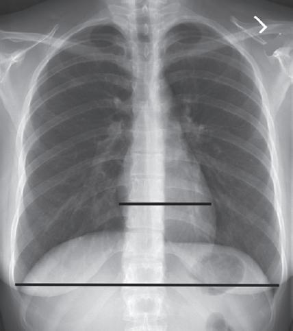
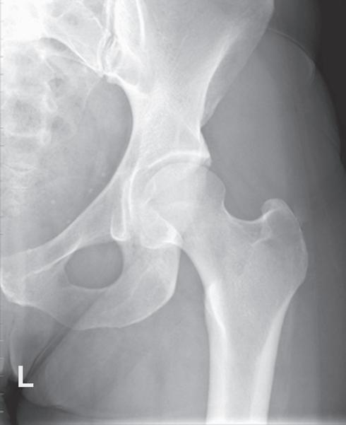
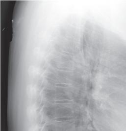
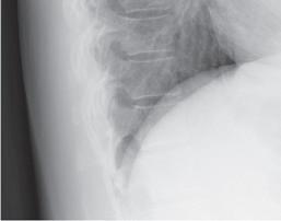
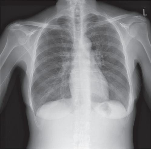
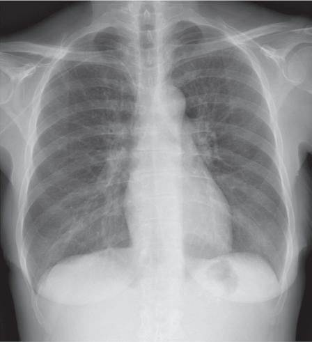
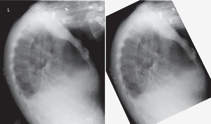
Consider how accuracy in positioning and technical factors affect the diagnostic value of a projection. Chest procedures are one of the most commonly performed projections each year. They are completed to evaluate the lungs, heart, and thoracic viscera, as well as disease processes such as pneumonia, heart failure, pleurisy, and lung cancer. The reviewer must consider all the normal variations that exist in areas such as the mediastinum, hila, diaphragm, and lungs. Should they also have to consider how the appearance of these structures is different with preventable positioning and technical errors? It takes only 2 or 3 degrees of rotation to affect the appearance of the lungs, causing differences in brightness values along the lateral borders of the chest projection (Fig. 1.1). Similarly, certain conditions such as mediastinal widening or cardiac size cannot be evaluated properly on a rotated posteroanterior (PA) chest projection. The normal heart shadow on such a projection will occupy slightly less than 50% of the transverse dimension of the thorax (Fig. 1.2). This is evaluated by measuring the largest transverse diameter of the heart on the PA or anteroposterior (AP) projection and relating that to the largest transverse measurement of the internal dimension of the chest. When the PA chest projection is rotated,
bringing a different heart plane into profile, this diagnosis becomes compromised.
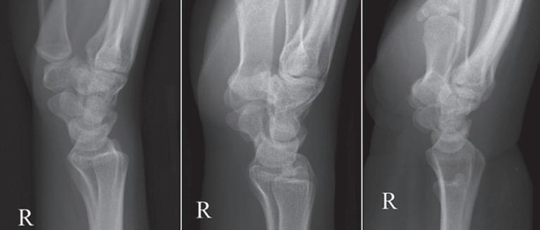
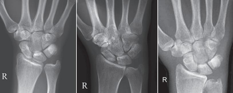
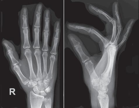
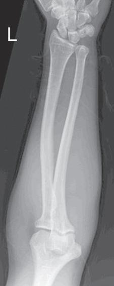
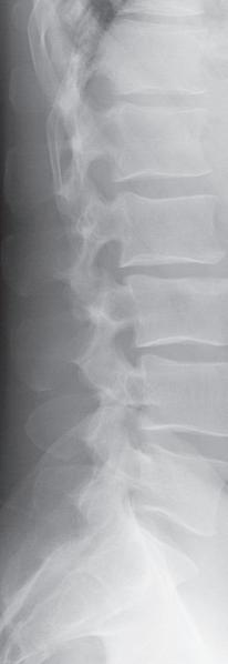
If instead of being evaluated for acceptability, projections are evaluated for optimalism, could more consistent and improved diagnoses be made from diagnostic projections? Figs. 1.3 and 1.4 demonstrate three lateral and PA wrist projections, all of which were determined to be acceptable and sent to the reviewer for diagnosis. Note how the trapezium is visualized only on the first lateral wrist projection but is not demonstrated on the other
FIGURE 1.1 Rotated PA chest projection.
FIGURE 1.2 Evaluating a PA chest projection for mediastinal widening.
two, and observe how the carpometacarpal joints and distal carpal bones are well visualized on the first PA wrist projection but are not seen on the other two projections. The first lateral wrist projection was obtained with the thumb depressed until the first metacarpal (MC) was aligned with the second MC, whereas the other lateral wrist projections were obtained with the first MC elevated. The first PA wrist projection was obtained with the MCs aligned at a 10- to 15-degree angle with the IR, the second PA wrist projection was taken with the MCs aligned at an angle greater than 15 degrees, and the third projection was taken with the MCs aligned at an angle less than 10 degrees. If the radiologist cannot arrive at a conclusive diagnosis from the projections that the technologist provides, he or she must recommend other imaging procedures or follow-up projections.
TERMINOLOGY
At the beginning of most chapters there is a list of key chapter terms. The glossary at the end of this text provides definitions of these terms.
CHARACTERISTICS OF THE OPTIMAL PROJECTION
An optimal image of each projection demonstrates all of the most desired features, as described in Box 1.1
Because of a patient’s condition, equipment malfunction, or technologist error, such perfection is not obtained for every projection that is produced. A less than optimal projection is thoroughly evaluated to determine the reason for error so that the problem can be corrected before the examination is repeated. A projection that is not optimal but is still acceptable according to a facility’s standards is carefully studied to determine whether skills can be improved before the next similar examination; continuous improvement is sought.
This text cannot begin to identify the variations in the standards of acceptability in all the different imaging facilities. What might be an acceptable standard in one facility may not be what is desired in another. As you study the projections in Chapters 3 to 12, you may find that many of them are accepted in your facility even though they do not meet the guidelines as written. You
Trapezium
FIGURE 1.3 Lateral wrist projections demonstrating the difference in trapezium visualization with thumb depression and elevation.
CMC joint
FIGURE 1.4 PA wrist projections demonstrating the difference in carpometacarpal (CMC) joint visualization with variations in metacarpal alignment with the IR.
BOX 1.1
Characteristics of the Optimal Projection
• Projection is accurately displayed
• Demographic information (e.g., patient and facility name, time, date) is visualized
• Correct marker(s) is in the appropriate position without superimposing the VOI
• Desired anatomic structures are in the exposure field and are in accurate alignment with each other
• There is maximum spatial resolution
• Radiation protection is present and was accurately used during the exposure
• Image histogram was accurately produced without errors
• Adequate exposure reached the IR based on ideal EI
• Contrast resolution identifies the subject contrast
• Noise is minimal (including scatter and preventable artifacts)
may also find that a guideline that is listed is not desired in your facility. The goal of this text is not to dictate what an acceptable or unacceptable projection is, because that is determined by the needs of the reviewer. The most common radiography positioning and exposure practices were used when deciding the positioning and image analysis guidelines that are listed in the tables for each projection.
IMAGE ANALYSIS PROCESS
After a projection is correctly displayed, it is evaluated for positioning and technical accuracy. Table 1.1 provides a systematic approach that is designed to be used when evaluating projections to ensure that all aspects of the projection are analyzed. Under each item in Table 1.1 there is a list of questions to explore while evaluating
Topics to Analyze Questions to Consider When Analyzing Projections
Demographic requirements are visualized on the projection
Projection is accurately displayed on the workstation monitor (Table 1.2)
Correct marker (e.g., R/L, arrow) is visualized on projection and demonstrates accurate placement (Table 1.3)
Appropriate collimation practices are evident (Table 1.4)
• Was the x-ray order associated with the correct patient?
• Are the patient’s name and age or birthdate, and patient identification number visible, and are they accurate?
• Are the examination time and date visible?
• Was the correct procedure algorithm selected on the workstation prior to starting the exam?
• Is the correct aspect of the structure positioned at the top and the right and left sides of the displayed projection?
• Is the marker face-up or reversed, as expected?
• If projection was flipped or rotated to improve display, does marker still indicate correct side as displayed?
• Is the marker visualized within the exposure field, and is it positioned as far away from the center of field as possible?
• Have specialty markers been added and correctly placed if applicable?
• Is the marker clearly seen without distortion, and is it positioned so it does not superimpose the VOI?
• Does the R or L marker correspond to the correct side of the patient?
• If more than one projection is on IR, have they both been marked if they are different sides of the patient?
• Are annotated markings correct?
• Are all of the required anatomic structures visible?
• Does the VOI fill the workstation screen?
• Was the long axis of the part aligned with the long axis of the IR?
• Was the CR centered to the center of the VOI?
• Is only the required VOI and 0.5–1 inches (1.25–2.5 cm) of the surrounding anatomy demonstrated on the projection?
• Is the collimated border present on all four sides of the projection when applicable?
• Is collimation within 0.5 inch (1.25 cm) of the skin line when applicable?
• Is collimation to the specific anatomy desired on projections requiring collimation within the skin line?
• Does the contrast mask align with the edges of the exposure field?
Relationships between the anatomic structures are accurate for the projection demonstrated (Tables 1.5–1.7)
Projection demonstrates maximum spatial resolution (Table 1.8)
• Are the relationships between the anatomic structures demonstrated as indicated in the procedural analysis sections of this textbook or defined by your imaging facility?
• Is the anatomic VOI in the center of the projection, or was the CR centered in the VOI?
• Does the projection demonstrate the least possible amount of size distortion?
• Does the projection demonstrate undesirable shape distortion?
• Are the joints of interest and/or fracture lines seen as open spaces?
• Was a small focal spot used when indicated?
• Was the appropriate SID used?
• Was the part positioned with the least amount of OID possible?
• Does the projection demonstrate signs of undesirable patient motion or unhalted respiration?
• Computed radiography: Was the smallest possible IR cassette used?
• Computed radiography: Are there signs of a double exposure?
EI, Exposure index; IR, image receptor; VOI, values of interest.
TABLE 1.1 Image Analysis Process
TABLE 1.1 Image Analysis Process—cont’d
Topics to Analyze Questions to Consider When Analyzing Projections
Radiation protection is present on projection when indicated, and good radiation protection practices are used during the procedure (Table 1.9)
Image histogram was accurately produced (see Tables 2.1 and 2.4)
• Was the exam explained to the patient, and were clear, concise instructions given during the procedure?
• Were immobilization devices used to prevent patient motion when needed?
• Was the minimal SSD of at least 12 inches (30 cm) maintained for mobile radiography?
• Was the possibility of pregnancy determined of all females of childbearing age?
• Is gonadal shielding evident and accurately positioned when the gonads are within the primary beam and shielding will not cover the VOI?
• Were radiation protection measures used for patients whose radiosensitive cells were positioned within 2 inches (5 cm) of the primary beam?
• Was the field size tightly collimated?
• Were exposure factors (kV, mA, and time) set to minimize patient exposure?
• If the AEC was used, was the backup time set to prevent overexposure to the patient?
• Are there anatomic artifacts demonstrated on the projection?
• Were personnel or family who remained in the room during the exposure given protective attire, positioned as far from the radiation source as possible, and present only when absolutely necessary and for the shortest possible time?
• Is the exposure indicator within the acceptable parameters for the system?
• Was the correct body part and projection chosen from the workstation menu?
• Was the CR centered to the VOI?
• Was collimation as close to the VOI as possible, leaving minimal background in the exposure field?
• Was scatter controlled with lead sheets, grids, tight collimation, etc.?
• If collimated smaller than the IR, is the VOI in the center of the projection and are all four collimation borders seen?
• Computed radiography: Was at least 30% of the IR covered?
• Computed radiography: If multiple projections are on one IR, is collimation parallel and equidistant from the edges of the IR and are they separated by at least 1 inch (2.5 cm)?
• Computed radiography: Was the IR left in the imaging room while other exposures were made and was the IR read shortly after the exposure?
• Computed radiography: Was the IR erased if not used within a few days?
Adequate exposure reached the IR (see Tables 2.5–2.9)
• Were the technical factors of mAs and kV set appropriately for the projection?
• Is the required subject contrast in the VOI fully demonstrated?
• Is the EI number obtained at the ideal level or within the acceptable parameters for the digital system?
• Is the brightness level adequate to demonstrate the VOI?
• Does the projection demonstrate quantum noise?
• Does any VOI structure demonstrate saturation?
• Is there a decrease in contrast and detail visibility caused by scatter radiation fogging?
• Was a grid used if recommended, and if so, was the appropriate grid ratio and technique used for the grid?
• Are there grid line artifacts demonstrated?
• Was the correct SID used for the exposure set?
• Was the OID kept to a minimum, and if not, were the exposure factors adjusted for the reduction in scatter radiation when applicable?
• If collimation was significantly reduced, were the technical factors adjusted for the reduction in scatter radiation when applicable?
• If a 17-inch field size was used, was the thinnest end of a long bone or vertebral column positioned at the anode end of the tube?
• Was exposure adjusted for additive and destructive patient conditions?
• If the AEC was used, was the mA station set to prevent exposure times less than the minimum response time?
• If the AEC was used, was the backup time set at 150%–200% of the expected manual exposure time for the exam?
• If the AEC was used, was the activated ionization chamber(s) completely covered by the VOI?
• If the AEC was used, is there any radiopaque hardware or prosthetic devices positioned in the activated chamber(s)?
• If the AEC was used, was the exposure (density) control on zero?
Contrast resolution is optimal for demonstrating the VOI
• If projection is less than optimal but acceptable, does windowing allow the VOI to be fully demonstrated?
• If projection is less than optimal but acceptable, does an alternate procedural algorithm improve contrast resolution enough to make the projection acceptable?
TABLE 1.1 Image Analysis Process—cont’d
Topics to Analyze Questions to Consider When Analyzing Projections
No preventable artifacts are present on the projection (see Table 2.10)
Ordered procedure and the indication for the exam have been fulfilled
• Are any artifacts visible on the projection?
• Can the artifact be removed?
• What is the location of any present artifact with respect to a palpable anatomic structure?
• Have you asked the patient about the nonremovable artifact’s origin (surgical implant, foreign body)?
• Does the projection have to be repeated because of the artifact?
• Can the artifact be removed?
• Have you asked the patient about any nonremovable artifact’s origin?
• Has the routine series for the body structure ordered been completed as determined by your facility?
• Do the projections in the routine series fulfilled the indication for the examination, or must additional projections be obtained?
• Projection is: optimal acceptable, but not optimal unacceptable If projection is acceptable but not optimal, or is unacceptable, describe what measures should be taken to produce an optimal projection.
AEC, Automatic exposure control; CR, central ray; EI, exposure index; IR, image receptor; L, left; OID, object–image receptor distance; SID, source–image receptor distance; R, right; SSD, source-skin distance; VOI, values of interest.
a projection. The discussions in Chapters 1 and 2 will explore these question areas. The answers to all the questions, taken together, will determine whether the projection is optimal, is acceptable, or needs repeating based on professional or departmental standards.
1. Demographic Requirements Are Visualized on the Projection
Projections are evaluated to be certain that the correct patient has been associated with the projections obtained on that patient before they are sent to a picture archival and communication system (PACS). This is accomplished with computed radiography when the cassette’s barcode label is scanned and associated with the patient’s identification barcode and examination request and with DR when the patient and examination order is pulled up on the workstation before the examination is obtained. It is when the projection being obtained is selected from the workstation that the algorithms used to display and rescale the projection are also selected.
Once a projection is sent to the PACS, it is immediately available to whoever has access, and it will make it difficult to retrieve. If the projection is allocated with the wrong patient, the projection may be seen or evaluated by a physician before the misassociation is noticed.
If incorrect patient information is assigned to a projection, the technologist can reassociate the examination to the correct patient as long as the projection has not been sent to the PACS. If the projections are sent to the PACS with the incorrect patient assigned to the examination, the PACS coordinator must be immediately
notified to correct the error before the projections are viewed.
2. Projection Is Accurately Displayed on the Workstation Screen
Digital images are displayed on the workstation screen in the manner that they were obtained or after a preprocessing algorithm has been applied that changes how the projection is to be displayed to meet the facilities’ desires (e.g., a left lateral chest projection may be transversely flipped to be displayed as a right lateral).
How the patient is oriented on the IR during the procedure determines if a projection will be displayed accurately on the workstation or if it will require postprocessing manipulation. Each digital system’s IR has a “top” and “right” or “left” side orientation. These orientation indicators align the image orientation with the computer algorithm of a patient in the anatomic position (AP projection). As long as the top indicator is placed under the portion of the anatomy that is to be up when the projection is displayed, the projection will be displayed with the correct anatomy at the top. On AP projections where the right and left sides of the patient are included (torso, skull, etc.), the patient’s right side is aligned with the right orientation indicator on the IR to accurately display the patient’s left side on the viewer’s right side. For PA projections, where the patient’s left side will be oriented with the right side of the IR during the procedure, the associated algorithm will request that the computer transversely flip the projection obtained before it is displayed. Table 1.2 lists display guidelines to explore when analyzing the display acceptability.
FIGURE 1.5 Orientation of patient with IR for proper display.
Patient and IR orientation
AP, PA, and AP/PA oblique projections of chest, abdomen, shoulder, nip, vertebrae, and cranium
Lateral projections
The quality of a projection may appear different depending on where it is displayed in the facility. Display station resolution refers to the maximum number of pixels that the screen can demonstrate. To display projections at full resolution, the display screen must be able to display the same number of pixels as those at which the digital system acquired the projection. If the digital system’s matrix size is smaller than the display station’s matrix size, the values of surrounding pixels are rounded up or down as needed to display the whole projection. The technologist’s workstation display screens typically do not demonstrate resolution as high as that of the radiologist’s display screens.
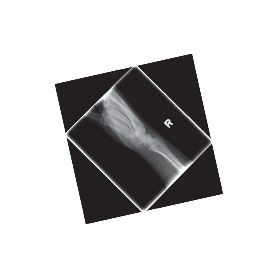
FIGURE 1.6 Diagonally displayed right lateral wrist projection. When possible, avoid positioning extremities diagonally on the IR if the projection cannot be rotated to be in degree increments on the workstation display or if when rotated, the projection does not adjust to fill the display monitor. Aligning the long axis of extremities with the longitudinal or transverse axis of the IR will prevent both issues.
• Choose the correct procedural algorithm (projection) on the workstation prior to the exam so the correct algorithm is used to display the projection after the exposure.
• Orient the aspect of the projection that should be on the top when the projection is displayed to the “top” on the IR when obtaining projection (Fig. 1.5).
• Avoid placing extremities diagonally on IR when possible (Fig. 1.6).
• Display as if the patient were standing in an upright position, with the viewer and the patient facing one another The right side of the patient on the projection is on the viewer’s left side
• AP or AP oblique: R or L marker appears correct when the projection is accurately displayed if it was placed on the IR face-up (Fig. 1.7).
• PA or PA oblique: R or L marker appears reversed if it was placed on the IR face-up (Fig. 1.8).
• Display in the same manner as the technologist viewed the patient when obtaining the projection.
• Right lateral: Patient faces the viewer’s left side Marker is correct if it was placed on the IR face-up
• Left lateral: Patient faces the viewer’s right side Marker is correct if it was placed on the IR face-up (Fig. 1.9).
TABLE 1.2 Projection Displaying Guidelines
TABLE 1.2
Projection Displaying Guidelines—cont’d
AP/PA (lateral decubitus) projections of chest and abdomen
Inferosuperior (axial) shoulder and axiolateral hip projections
Extremity projections
Adjusting for poor display
• Display as if the viewer and patient are facing one another, with the side of the patient that was positioned upward when the projection was taken placed upward on the displayed projection (Fig. 1.10).
• AP: R or L marker is correct.
• PA: R or L marker is reversed.
• Display so the anterior surface is up and the posterior surface is down (Fig. 1.11).
• Marker is placed anteriorly
• Display as if the viewer’s eyes were going through the projection in the same manner the CR went through the extremity when the projection was taken. A right PA hand projection is displayed with the thumb positioned toward the viewer’s left side and a right lateral hand projection is displayed so the palmar side of the hand is positioned toward the viewer’s left side (Fig. 1.12).
• Finger, wrist, and forearm: Display as if the patient were hanging from the fingertips
• Elbow and humerus: Display as if they were hanging from the shoulder
• Toes(s) and AP and AP oblique foot: Display as if they were hanging from the toes
• Lateral foot, ankle, lower leg, knee, and femur: Display as if they were hanging from the hip
• Digital projections that have been displayed inaccurately can be flipped horizontally and vertically and rotated before being saved to the PACS (Fig. 1.13).
AP, Anteroposterior; CR, central ray; IR, image receptor; L, left; PA, posteroanterior; PACS, picture archival and communication system; R, right.
3. Correct Marker Is Visualized on Projection and Demonstrates Accurate Placement
Lead markers are used to identify the patient’s right and left sides, indicate variations in the standard procedure, or show the amount of time that has elapsed in timed procedures, such as small bowel studies. The markers are constructed of lead so they are radiopaque. Each projection must include a correctly placed marker. Table 1.3 lists guidelines to follow when marking and evaluating marker accuracy on projections.
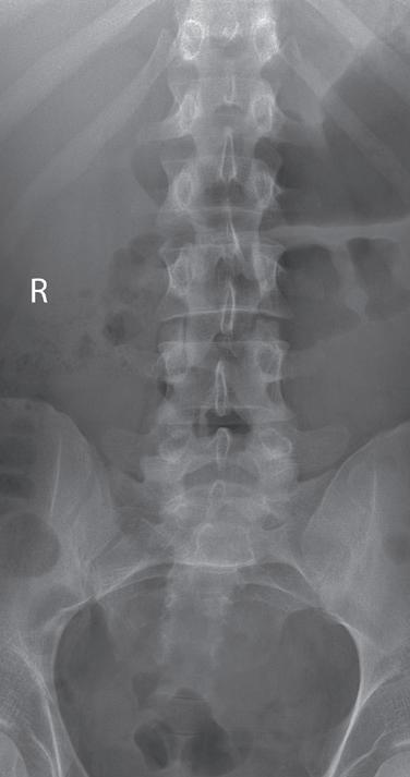
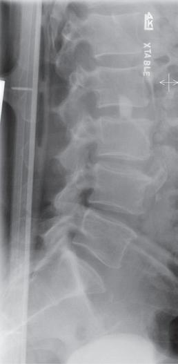
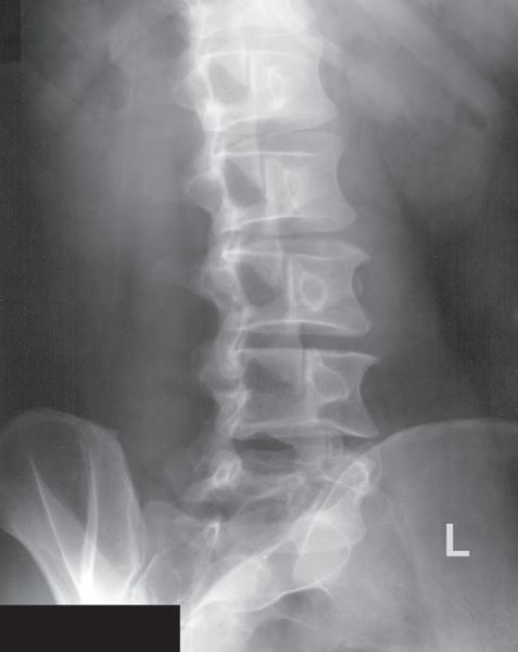
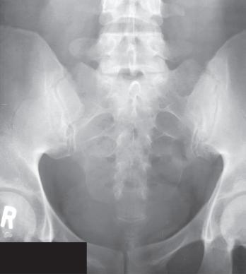
FIGURE 1.7 Accurately displayed and marked AP lumbar vertebrae projection.
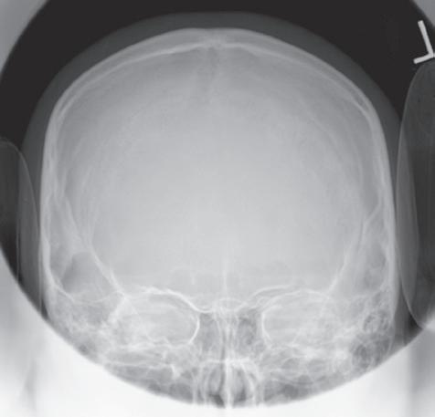
FIGURE 1.8 Accurately displayed PA cranium projection.
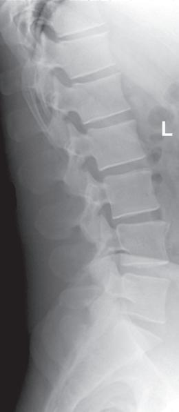
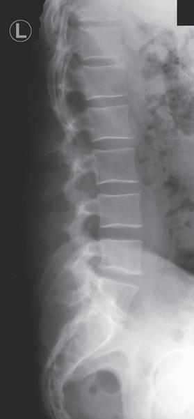
FIGURE 1.9 Accurately displayed left lateral lumbar vertebrae projection.
L Sideup
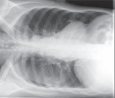
FIGURE 1.10 Accurately displayed and marked AP (right lateral decubitus) chest projection.
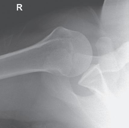
FIGURE 1.11 Accurately displayed and marked inferosuperior (axial) shoulder projection.
FIGURE 1.12 Accurately displayed right PA and lateral hand projections.
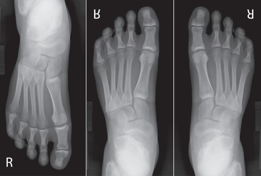
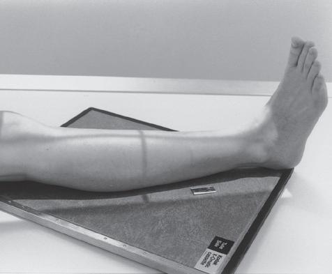
FIGURE 1.13 An AP foot projection that has been displayed upside down, vertically flipped for poor display, and rotated for accurate display. The first AP foot projection was obtained using DR and with the patient seated on the imaging table with the toes pointing toward the foot end of the table. A face-up R marker was placed in the exposure field. Because the patient was not oriented on the IR to have the toes at the top when displayed, the projection was displayed upside down on the workstation monitor. If the projection was vertically flipped to accurately display it, the marker will be reversed and the foot displayed as if it were a left foot instead of a right, as demonstrated in the second foot projection. If the first foot projection was rotated instead of being flipped, the marker will remain face-up and the foot will be displayed accurately, as demonstrated on the third foot projection.
TABLE 1.3 Marker Placement
General guidelines
• Position marker within the exposure field as far away from the center of the field as possible
• Avoid placing marker in an area that will cover up the VOI (Fig. 1.14) or be hidden by a shield. If tape is used to secure the marker in place, it should also not cover up the VOI, because it may be seen as an artifact.
• Place marker directly on the IR or imaging tabletop whenever possible in a face-up position. This placement avoids marker distortion and magnification, prevents scatter radiation from undercutting the marker, and ensures that the marker will not be projected off the IR (Fig. 1.15).
• Do not place the marker directly on the skin.
• Replace the tape on markers regularly to prevent transmission of bacteria from patient to patient.
AP/PA projections of torso, vertebrae, and cranium
Lateral projections of torso, vertebrae, and cranium
AP/PA oblique projections of torso, vertebrae, and cranium
• Place the R or L marker laterally on the side being marked.
• Vertebral column is the dividing plane for the right and left sides If marking the right side, position the R marker to the right of the vertebral column; if marking the left side, position the L marker to the left of the vertebral column (Fig. 1.7).
• Marker indicates the side of the patient positioned closer to the IR. If the left side is positioned closer to the IR, place an L marker on the IR (Fig. 1.16).
• Whether the marker is placed anteriorly or posteriorly to the torso or vertebrae does not affect the accuracy of the marking, although the projections of markers placed posteriorly are often obscured by scatter (Fig. 1.17).
• Marker identifies the side of the patient positioned closer to the IR and is placed on the correct side of the patient (Fig. 1.18).
• Vertebral column is the plane used to divide the right and left sides of the body
1.17 Markers placed posteriorly on lateral torso or vertebrae projections often have to be annotated because they are obscured by scatter.
FIGURE 1.14 Left lateral lumbar vertebrae projection with marker superimposing VOI.
FIGURE 1.15 Markers that have been magnified, distorted, and undercut with scatter radiation.
FIGURE 1.16 Marker placement for lateral lumbar vertebrae projection.
FIGURE
AP/PA (lateral decubitus) projections of torso
• Place the R or L marker laterally on the side being marked. The vertebral column is the dividing plane for the right and left sides.
• Marker is less likely to obscure the VOI if the side of the patient that is positioned up, away from the cart or imaging table on which the patient is lying is the side marked.
• Place an arrow marker pointing up toward the ceiling or lead lettering to indicate which side of the patient is positioned away from the cart or imaging table (Fig. 1.10).
Extremity projections
• Mark the right or left side of the patient being imaged.
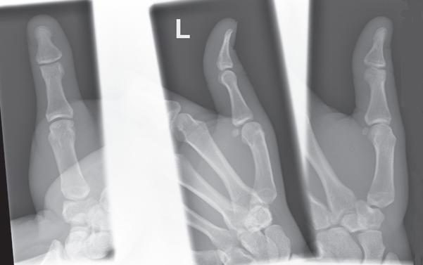
• When multiple projections of the same anatomic structure are placed on the same IR, mark only one of the projections (Fig. 1.19).
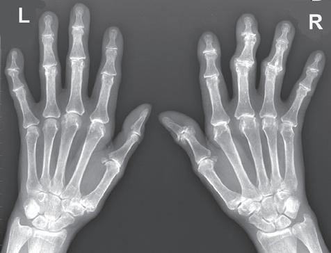
• If projections of a right and a left anatomic structure are placed on the same IR, mark both projections with the correct R or L marker (Fig. 1.20).
AP and AP oblique projections of shoulder and hip
Cross-table lateral projections
Postexam annotation
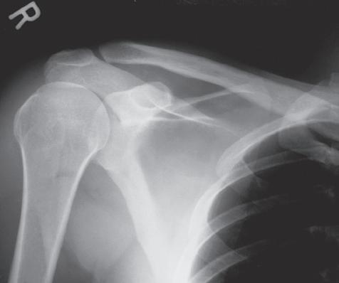
• Marker used indicates the side of the patient being imaged (Fig. 1.21).
• Place marker laterally to prevent it from obscuring medial anatomic structures and to eliminate possible confusion about which side is being imaged (Fig. 1.22)
• Marker used indicates the right or left side of the patient when the extremities, shoulder, or hip is imaged (Fig. 1.11) and the side of the patient positioned closer to the IR when the torso, vertebrae, or cranium is imaged (Fig. 1.9).
• Place the marker anteriorly to prevent superimposition of structures that are at the posterior edge of the IR.
• Facilities may allow postexam annotation when a marker is missing or only partially visualized on the resulting projection. Position any annotated markings as described above.
• If marker is only partially demonstrated, place the annotated marker next to the partial one without covering it up (Fig. 1.23).
4. Appropriate Collimation Practices Are Evident
FIGURE 1.18 Marker placement for AP oblique lumbar vertebrae projection.
Good collimation practices:
• Clearly delineate the values of interest (VOI).
• Decrease radiation dosage by limiting the amount of patient tissue exposed.
• Improve the visibility of recorded details by reducing the amount of scatter radiation that is produced.
• Reduce histogram analysis errors.
Each projection requires that the CR be centered to a particular location and that it is collimated to a particular VOI. For example, all wrist projections require that onefourth of the distal forearm be included because radiating wrist pain may be a result of a distal forearm fracture, and a lateral ankle projection includes 1 inch (2.5 cm) of the fifth metatarsal base to rule out a Jones fracture. For each projection presented in Chapters 3 to 12 there are guidelines on what makes up the VOI on the projection and a description of how to collimate to include the VOI (Table 1.4).
5. Relationships Between the Anatomic Structures Are Accurate for the Projection Demonstrated
Each projection is to demonstrate specific bony relationships that will best facilitate diagnosis as defined in the Text continued on p. 18
AP, Anteroposterior; IR, image receptor; L, left; PA, posteroanterior; R, right; VOI, values of interest.
FIGURE 1.19 Marker placement for unilateral finger projections on one IR.
FIGURE 1.20 Marker placement for bilateral PA hand projections.
FIGURE 1.21 Marker placement for an AP projection of shoulder.
FIGURE 1.22 Poor marker placement on an AP projection of hip.
General guidelines
• To allow for even collimation on all sides, obtain the tightest collimation and provide the best positioning for good exposure field recognition, align the long axis of the part to the long axis of the IR, center the CR to the center of the VOI, and narrow the radiation beam on all sides to include only the required VOI and 0.5–1 inch (1.25–2.5 cm) of the surrounding anatomy (Figs. 1.24–1.26).
• When the structure being imaged is smaller than the IR, collimation is brought to within 0.5 inch (1.25 cm) of the closest skin line.
• VOI fills the display screen demonstrating tight collimation (Fig. 1.27)
• Each projection should demonstrate a small collimated border around the entire VOI, unless the entire IR is covered.
FIGURE 1.23 Partially visible marker and annotation.
TABLE 1.4 Collimation Best Practices
FIGURE 1.24 Proper “to skin line” collimation on an AP forearm projection.
FIGURE 1.25 Proper “to skin line” collimation on a lateral chest projection.
FIGURE 1.26 Proper collimation on an AP sacral projection
TABLE 1.4 Collimation Best Practices—cont’d
Rotating the collimator
Overcollimation
Using the collimation borders to determine CR placement
Long bones
Collimator guide
Collimator light field on patient versus actual coverage on IR
• Rotate the collimator to align it with anatomic structures that are not aligned with the longitudinal or transverse axis of the IR (Fig. 1.28).
• Collimator rotation does not affect the alignment of the beam with the grid because this alignment is affected only when the tube column is rotated and is demonstrated on the projection by visualization of grid line artifacts and grid cutoff.
• Results in the clipping of required anatomy on the projection (Fig. 1.29).
• To prevent clipping of extremity structures that are positioned at a greater OID, view the shadow of the magnified structure that is projected onto the IR by the collimator light and allow the collimated field to remain open enough to include the shadow (Fig. 1.30).
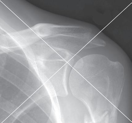
• Collimated borders on a projection can be used to determine the exact location of CR placement by making an imaginary X on the projection by diagonally connecting the corners of the collimated border (Fig. 1.31). The center of the X indicates the CR placement for the projection.
• When imaging long bones that require both joints to be included on the projection, choose a large enough IR and open the collimation field so it extends 1–2 inches (2.5–5 cm) beyond each joint space. This prevents the off-centered joints from being projected off the IR when they are projected in the direction of the diverged x-ray beams that are used to record them (Fig. 1.32).
• Place long bones diagonally on IR only when both joints are required and can only fit on IR when placed diagonally (Fig. 1.33).
• The collimation guide can be used to determine the actual IR coverage (Fig. 1.34).
• When the collimator’s CR indicator is positioned on the torso and the collimator is set to a predetermined width and length, the light field demonstrated on the torso does not represent the true width and length of the field set on the collimator. This is because the x-rays will continue to diverge as they move through the torso to the IR, increasing the field’s size as they do so (Fig. 1.35).
• The thicker the body part being imaged, the smaller the collimator’s light field that appears on the skin surface.
Contrast masking versus good collimation
• Postprocessing contrast masking adds a black background around the VOI, providing a perceived enhancement of image contrast.
• Contrast masking is to only extend to the exposed areas, matching the collimation borders
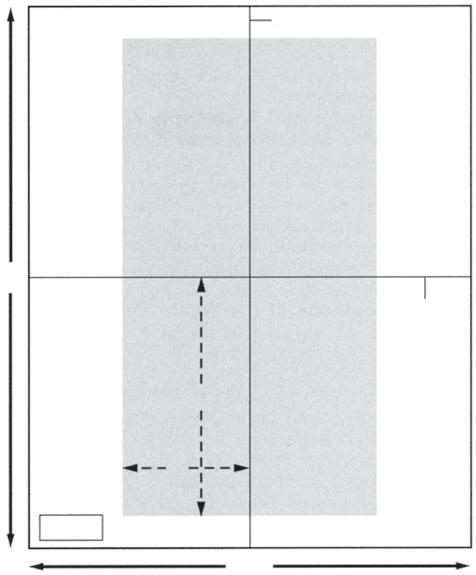
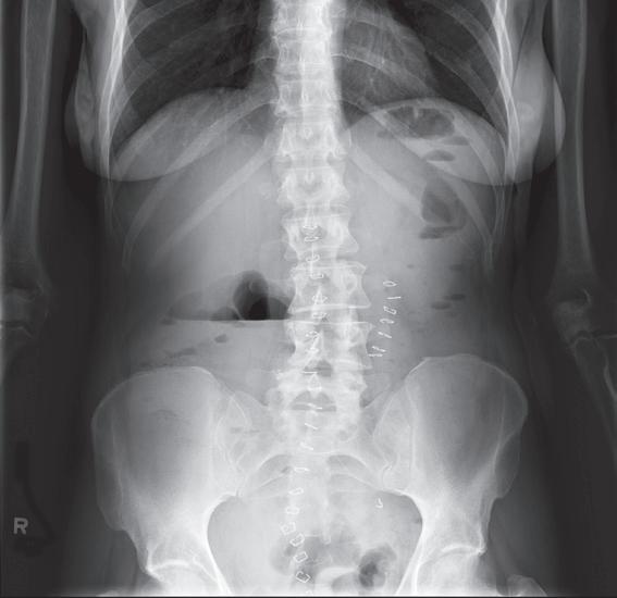
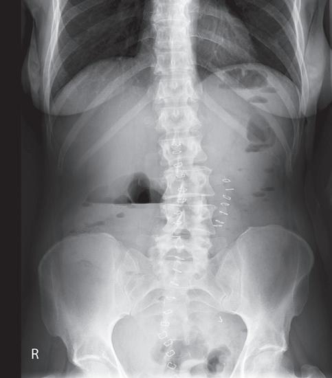
• Contrast masking does not replace good collimation practices and should not be used to present a perceived radiation dose savings to the patient by moving one or more of the sides into the exposed region (Fig. 1.36). If done unevenly, the perceived location of the CR is changed on the masked projection.
• A projection that has been masked and sent to the PACS cannot be unmasked.
FIGURE 1.27
Collimation determines how the VOI will fill the workstation screen. The first AP chest projection was obtained with less collimation than the second. Note how collimation determines how the display screen will be filled.
CR, Central ray; IR, image receptor; OID, object–image receptor distance; PACS, picture archival and communication system; VOI, values of interest.
FIGURE 1.28 Nonrotated and rotated collimator head on tilted lateral chest projection to obtain tighter collimation.
FIGURE 1.29 Overcollimation on a lateral lumbar vertebral projection.
FIGURE 1.30 Viewing the hand’s shadow to determine proper collimation.
1.32 Proper positioning of long bones with diverged x-ray beam.
FIGURE 1.31 Using collimated borders to locate CR placement.
FIGURE
FIGURE 1.33 Diagonally positioning long bones on the IR to include both joints.
Longitudinal IR midline
demonstration of specific anatomic structures and pathologic conditions.
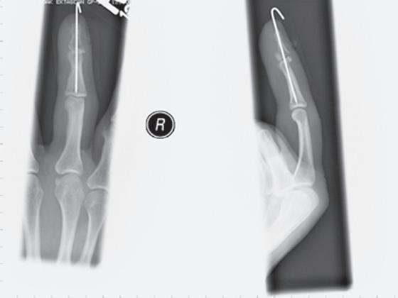
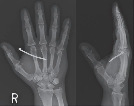
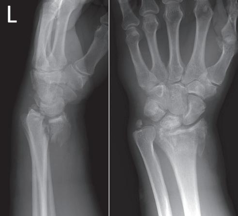
procedural analysis sections of this text. Most positioning routines require AP-PA and lateral projections to be taken to demonstrate superimposed anatomic structures, localize lesions or foreign bodies (Fig. 1.37), and determine alignment of fractures (Fig. 1.38). When joints are of interest, oblique projections are also added to this routine to visualize obscured areas better. In addition to these, special projections may be requested for more precise
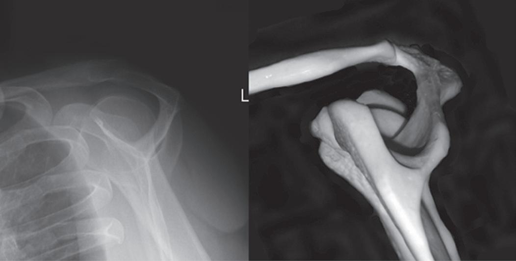
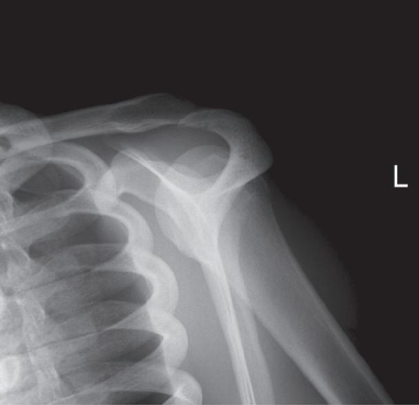
To appreciate the importance of the anatomic relationships on a projection, one must understand the clinical reason for what the procedure is to demonstrate for the reviewer. An optimally positioned tangential (supraspinatus outlet) shoulder projection (Fig. 1.39) demonstrates the supraspinatus outlet (opening formed between acromion and humeral head) and the posterior aspects of the acromion and acromioclavicular (AC) joint in profile. The technologist produces these anatomic relationships when the midcoronal plane is positioned vertically and it can be ensured that the proper positioning was obtained when the superior scapular angle is positioned at the level of the coracoid tip on the projection. From this optimal projection the radiologist can evaluate the supraspinatus outlet for narrowing caused by variations in the shape (spur) or slope of the acromion or AC joint, which has been found to be the primary cause of shoulder impingements and rotator cuff tears. If instead of being vertical, the upper midcoronal plane was tilted toward the IR, the resulting projection would demonstrate the superior scapular angle positioned above the coracoid tip, preventing clear visualization of the acromion and AC joint deformities, because their posterior surfaces would no longer be in profile and would narrow or close the supraspinatus outlet (Fig. 1.40). Because the reviewer would be unable to diagnose outlet narrowing that results from variations in the shape or slope of the
FIGURE 1.34 Marker placement for tightly collimated image.
FIGURE 1.35 Collimator light field versus IR coverage.
FIGURE 1.36 AP abdomen projections with and without contrast masking. The first projection shows that the arms were included along the sides of the torso. The second projection has the contrast mask exceeding into the exposure field, excluding the arms and hiding that they were included in the exposure. Because the second projection was equally masked on both sides, the perceived placement of the CR is the same as the original projection. If the contrast mask exceeded into the exposure field on only one side, the perceived location of the CR placement will move in the same direction.
FIGURE 1.37 PA and lateral hand projections to identify location of foreign body (nail).
FIGURE 1.38 Lateral and PA wrist projection to demonstrate distal forearm fracture alignment.
Superior scapular angle
Supraspinatus outlet AC joint
Coracoid tip
FIGURE 1.39 Properly positioned skeletal bones and shoulder in the tangential (supraspinatus outlet) projection.