

VISION PLAN — November 2024 —
Our Future 35 is a community-centered initiative to create public spaces along the I-35 corridor that reconnects East and West Austin.
Because the Texas Department of Transportation (TXDOT)’s I-35 Capital Express Central project will lower the highway’s main lanes between Lady Bird Lake and Airport Boulevard, the City of Austin has a once-in-a-generation opportunity to construct “caps” and “stitches” over the highway, reconnecting the two sides of I-35 after decades of divide.
Combined, these opportunities could create up to 25 acres of regionally significant new public space in the middle of Central Austin.
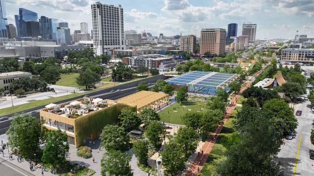
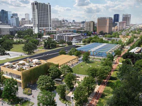
Artist rendering of a cap over I-35 between Cesar Chavez and 4th Street, looking north

CITY COUNCIL
Kirk Watson, Mayor
Natasha Harper-Madison, District 1
Vanessa Fuentes, District 2
Jose Velasquez, District 3
Jose “Chito” Vela, District 4
Ryan Alter, District 5
Mackenzie Kelly, District 6
Leslie Pool, District 7
Paige Ellis, District 8
Zohaib “Zo” Qadri, District 9
Alison Alter, District 10
CITY OF AUSTIN RESIDENTS
CITY OF AUSTIN STAFF
TC Broadnax, City Manager
Robert Goode, Assistant City Manager
Richard Mendoza, TPW Director
Upal Barua, TPW Assistant Director
Karla Taylor, TPW Chief of Staff
Michelle Marx, Transportation Officer
Brianna Frey
Sadra Dehghan
Shannon Riley
Alyssa Ruiz
Heather Bishop
Eric Bollich
Nathan Wilkes
Jeff Stensland
Noelle Corcoran
Jack Flagler
Lee Nichols
ACKNOWLEDGEMENTS
CONSULTANT TEAM
Arup US, Inc.
Lionheart Places LLC
Kilograph
Overland Partners
Garza EMC LLC
Square One Consultant, Inc.
Cortez Consulting
Carter Design Associates
Hood Design Studio
James Lima Planning and Development
Transcend Planning and Engineering
The F A Bartlett Tree Expert Company
Public City LLC
COMMUNITY PARTNERS
Downtown Austin Alliance
OUR FUTURE 35 COMMUNITY STEERING COMMITTEE MEMBERS
(October 2022 – January 2024)
Instrumental in developing this plan’s Vision and Goals

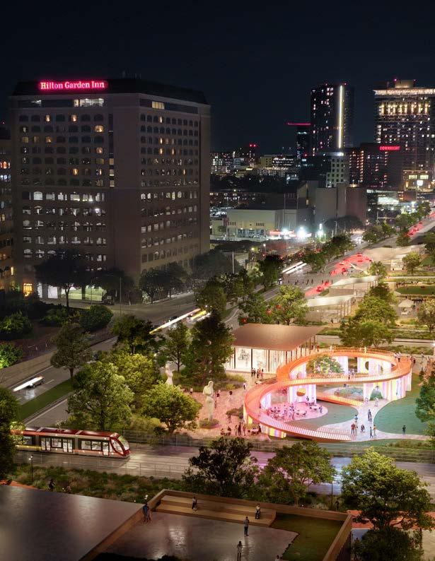
New on-cap pedestrian and bicycle connection across I-35 at 3rd Street, facing west toward downtown.
EXECUTIVE SUMMARY
What is Our Future 35?
Our Future 35 is a community-centered initiative to reconnect East and West Austin along I-35. Because the Texas Department of Transportation (TXDOT) will lower the highway’s main lanes between Lady Bird Lake and Airport Boulevard, the City of Austin has a once-in-a-generation opportunity to construct “caps” and “stitches” over the highway. Combined, these opportunities could create up to 25 acres of regionally significant new public space in the middle of Central Austin and reconnect the two sides of I-35 after decades of divide.

What is a Vision Plan?
The Our Future 35 Vision Plan documents the community’s desired outcomes and priorities for Austin’s Cap and Stitch effort and will act as a road map, guiding future amenity designs as individual caps are proiritized and funded. This Vision Plan will become the foundation by establishing both corridor-wide and cap-specific guidance as design efforts move forward.
THE OUR FUTURE 35 VISION PLAN INCLUDES:
• A Vision Statement for Austin’s Cap and Stitch Program
• Six overarching Goals
• Amenity design Concepts articulating desired cap character and amenities, and illustrating how the Our Future 35 Vision and Goals may be implemented on new caps and stitches
Klyde Warren Park in Dallas is a well-known examples where a sunken freeway has been transformed into a vibrant community hub.
EXECUTIVE SUMMARY
Our Future 35 Vision and Goals
The Vision and Goals for Our Future 35 were developed from extensive community engagement and reflect Austinites’ desired outcomes for the City’s Cap and Stitch effort. As designs for future caps and stitches move forward, proposed on-cap amenities and programming should align with the Vision and Goals to ensure that proposals reflect these community needs.
VISION STATEMENT:
New shared public spaces over I-35 are inclusive and sustainable, support economic opportunity and equity, celebrate heritage and cultural narratives, support community health and restorative natural spaces, encourage environmental stewardship and promote safe and comfortable access to all citizens.
Program Goals:


EQUITY AND INCLUSIVITY: Engage community members who have been impacted by and excluded from past infrastructure decisions and ensure that new amenities are dynamic, sustainable and welcome communities of all races and identities.
ECONOMIC AFFORDABILITY AND VITALITY: Foster design elements and activations for small and local businesses and mitigate displacement and adverse cost of living impacts of the project on surrounding neighborhoods and communities of color.
HEALTH AND HUMAN NATURE: Create spaces that enhance the quality of life and wellbeing for users, encourage active transportation, employ native and adapted resilient and restorative landscapes and promote connection to nature.
COMMUNITY AND CULTURAL NARRATIVES: Celebrate the historical and cultural fabric of past and present communities surrounding I-35 while recognizing the city and highway’s histories of fracture, and collect and amplify the narratives and histories of community members.
SAFETY AND CONNECTIVITY: Connect community members to jobs, services and each other and promote safe and comfortable hubs that provide access to, from and across I-35 and foster modes of travel that welcome and support all ages and abilities.
ENVIRONMENTAL SUSTAINABILITY: Advance the Austin community’s commitment to environmental stewardship, recognize broader climate action imperatives and build the capacity to successfully maintain and adapt these spaces.
EXECUTIVE SUMMARY
Where are Caps and Stitches Possible?
The Our Future 35 team has worked closely with the Texas Department of Transportation (TXDOT)’s I-35 Capital Express Central project to identify potential locations for caps and stitches.
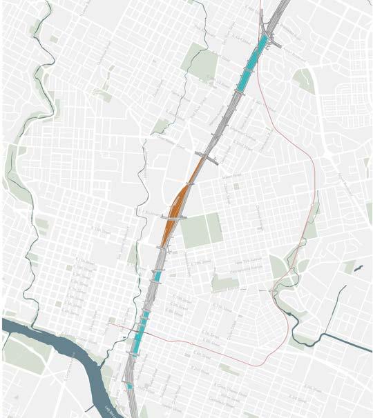
The University of Texas and Texas Department of Transportation are discussing potential highway caps adjacent to the UT campus. Those potential caps would not be funded or built by the City of Austin.
EXECUTIVE SUMMARY
What Benefits Could Caps Provide in Austin?
Our Future 35 has the potential to bring major benefits to Austin and to the region, including but not limited to:


Reconnecting Communities: Caps and stitches can enhance the connection between two sides of a highway that were once connected but were separated with the original highway construction. Caps and stitches cannot undo the historic impacts the highway’s construction caused, but it can create space where all are invited to partake in celebration and civic participation.
Creating Signature New Public Space for Citywide Use: Caps and stitches can transform unused or underutilized space currently dedicated to highway uses into valuable and functional city real estate that provides community benefits.
Supporting Local Businesses: Caps and stitches create new real estate that can be used to support the local economy by providing affordable spaces to help incubate and grow small businesses. This could include providing space for food halls, markets and affordable retail space and providing economic development opportunities catering to residents and visitors.
Provide Space for Arts and Culture: Caps and stitches can provide new, affordable space for Austin’s iconic art, music, and other creative expression to showcase the energy that makes Austin a unique cultural scene. This could include providing new spaces for events and performances, indoor and outdoor exhibition space, studios and arts markets.
Reclaiming Space for Nature: Caps and stitches can introduce new green space, parks and recreational areas into the central city and provide Austin residents with access to natural features like trees, naturescapes and gardens.
Building for Resilience: Austin is experiencing the acute effects of climate change with hotter summers, longer droughts and more intense rain events. New interventions (e.g., trees, shading, stormwater management, renewable energy) on caps and stitches can help Austin combat climate change issues, providing the infrastructure and spaces needed for community resilience. New trails, parks, recreational facilities and resilience hubs can support environmental sustainability as well as health and wellness.
Improved Bicycle and Pedestrian Connections: Caps and stitches over the highway can make biking and walking along and across I-35 more safe and comfortable.
EXECUTIVE SUMMARY
How Can Austin Implement the Our Future 35 Vision Over Time?
The design, construction, and operation of caps and stitches over TXDOT’s I-35 highway will be a complex, multi-year effort that will require intergovernmental cooperation, community partnerships and multiple funding sources.
The three distinct components of new highway caps that may be phased over the next several years include:
Roadway support elements, such as the columns and footings required to support cap decks. Funding for roadway elements must be identified first, since these elements must be constructed concurrently with TxDOT’s I-35 Capital Express Central project. Constructing roadway support elements as a first phase preserves the opportunity to build cap decks at a future date as funding becomes available.
Cap decks, the horizontal structures that span across the highway, on top of which public space amenities are provided. Provided that the roadway elements are in place, the City has a few opportunities to fund and construct cap decks.
Surface amenities can generally be constructed by the City upon completion of TxDOT’s construction project. Surface amenities themselves may also be constructed in phases as funding is identified.
Roadway Elements
2
and Tunnel Elements
4
Amenities (grass and trees)
Because TxDOT will construct the structural elements for City-funded caps in conjunction with their Capital Express Central Project, design and construction of the elements in this Vision Plan will require close partnership and coordination with TxDOT to meet milestones and avoid delays to the TxDOT project.
THE
WHAT IS OUR FUTURE 35?
The Our Future 35 project aims to transform the I-35 corridor in Austin from a highway barrier into a community asset.
With the Texas Department of Transportation (TxDOT) proposal to widen and lower I-35 through central Austin, the City has an opportunity to leverage the work planned by TxDOT to connect East and West Austin through new “caps” and “stitches” that can assist in making important strides toward unifying and mending the divide created by the original construction of I-35 and replacing it with marquee new public space.
The City of Austin’s Our Future 35 initiative is the result of years of grassroots community efforts. In 2020, the Downtown Austin Alliance organized an Urban Land Institute National Advisory Services Panel (ULI), which developed a “roadmap” for how to create a series of widened crossings and highway caps as part of the TxDOT Capital Express Central project. Following the ULI study, the Downtown Austin Alliance started a series of community conversations called Our Future 35 and convened a communitybased Scoping Working Group to help shape input to TxDOT during the early stages of their Capital Express Central project.
Now, the City of Austin is championing the next phase of this once-ina-generation effort to create new caps and stitches over the freeway between Ladybird Lake and Airport Boulevard to create a more connected, livable and sustainable Austin with amenities that will serve the City and the region.
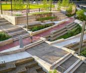

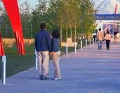
Central 70 Public Park, Denver, CO
Frankie May Pace Park, Pittsburgh, PA
Klyde Warren Park, Dallas, TX
Olympic Sculpture Park, Seattle, WA
HISTORY OF I-35 IN AUSTIN
The legacy of I-35 in Austin is synonymous with Austin’s history of displacement, segregation and exclusionary zoning. Since 1962, I-35 has been a primary driver of segregation and disparity. It is a concrete divide that is poorly suited to the community and presents a major roadblock to access, mobility and economic opportunity.
East Avenue, where I-35 stands today, was once a vibrant gathering place, a boulevard known for its park-like, tree-lined medians that were once used for family picnics, conversations, musical performances, sports and even Tillotson College convocations. However, in 1928, East Avenue began its trajectory toward becoming a street that symbolized segregation.
Austin’s 1928 City Plan included a zoning strategy to isolate minorities on the east side of East Avenue, making this area the only part of the city where Black Americans could access schools and other public services. The legalized segregation by the 1928 Master Plan evolved into the effective and real segregation of Blacks and Hispanics in East Austin. The construction of the I-35 freeway in the place of East Avenue in the 1950s and 1960s subsequently transformed the invisible redline of Austin’s 1928 plan into a true physical barrier.
As TxDOT now prepares to widen and lower portions of the Austin I-35 corridor, the City has an opportunity to address the divide created by the original construction of I-35 and replace it with amenities that celebrate and connect all Austinites.


East Avenue 1947
East Avenue
WHAT ARE CAPS AND STITCHES?
Caps and stitches are concrete decks over a highway that cover the traffic lanes below and provide urban amenities such as park space, buildings and bicycle and pedestrian connections on top. Caps and stitches can help reconnect the city at street level over the sunken highway and create new urban land in areas previously dedicated exclusively for the highway. Klyde Warren Park in Dallas and the Central 70 Cover Park in Denver are examples of well-known examples where a sunken freeway has been transformed into a vibrant community hub.
A “cap” is a deck over the highway that is greater than 300 feet long, creating a tunnel condition for the highway beneath. A “stitch” is a highway deck that is less than 300 feet long, similar to a widened bridge over the highway.
Hike
Kiosks
Highway Beneath
WHAT BENEFITS COULD CAPS PROVIDE IN AUSTIN?
What Benefits Could Caps Provide in Austin?
Our Future 35 has the potential to bring major benefits to Austin and to the region, including but not limited to:


Reconnecting Communities: Caps and stitches can enhance the connection between two sides of a highway that were once connected but were separated with the original highway construction. Caps and stitches cannot undo the historic impacts the highway’s construction caused, but it can create space where all are invited to partake in celebration and civic participation.
Creating Signature New Public Space for Citywide Use: Caps and stitches can transform unused or underutilized space currently dedicated to highway uses into valuable and functional city real estate that provides community benefits.
Supporting Local Businesses: Caps and stitches create new real estate that can be used to support the local economy by providing affordable spaces to help incubate and grow small businesses. This could include providing space for food halls, markets and affordable retail space and providing economic development opportunities catering to residents and visitors.
Provide Space for Arts and Culture: Caps and stitches can provide new, affordable space for Austin’s iconic art, music, and other creative expression to showcase the energy that makes Austin a unique cultural scene. This could include providing new spaces for events and performances, indoor and outdoor exhibition space, studios and arts markets.
Reclaiming Space for Nature: Caps and stitches can introduce new green space, parks and recreational areas into the central city and provide Austin residents with access to natural features like trees, naturescapes and gardens.
Building for Resilience: Austin is experiencing the acute effects of climate change with hotter summers, longer droughts and more intense rain events. New interventions (e.g., trees, shading, stormwater management, renewable energy) on caps and stitches can help Austin combat climate change issues, providing the infrastructure and spaces needed for community resilience. New trails, parks, recreational facilities and resilience hubs can support environmental sustainability as well as health and wellness.
Improved Bicycle and Pedestrian Connections: Caps and stitches over the highway can make biking and walking along and across I-35 more safe and comfortable.
WHERE ARE CAPS AND STITCHES POSSIBLE?
The Our Future 35 team has worked closely with TxDOT to identify potential locations for caps and stitches. TxDOT has confirmed that a cap or stitch over the highway is possible at the following locations:
Potential Cap and Stitch Locations

The University of Texas and Texas Department of Transportation are discussing potential highway caps adjacent to the UT campus. Those potential caps would not be funded or built by the City of Austin.
WHERE ARE CAPS AND STITCHES POSSIBLE?
Locations for potential caps and stitches are based on TxDOT’s design configurations for the new highway, highway ramps and frontage roads.
For a cap location to be viable and meet TxDOT criteria, the cap needs to have at least a 16½ foot height vertical clearance above the roadway surface below it, as well as from any highway ramps in order to accommodate vehicular traffic below the caps.
This requirement limits the locations where caps over the highway are possible, given TxDOT’s design for the highway.The potential cap and stitch locations figure on page 12 illustrate the locations where this minimum vertical clearance can be provided.
Roadway Clearance Requirement

WHAT IS POSSIBLE ON CAPS AND STITCHES?
In addition to open space and park amenities, caps and stitches can be engineered to support the additional loading needed to hold the weight of buildings on top. Buildings taller than two stories would require additional engineering to the cap structures in order to bear the additional weight of taller buildings. This would result in significant additional structural costs that the City would have to bear, costs that are unlikely to be offset by the proceeds of the additional building space created. For these reasons, buildings on City-funded caps will be limited to two stories. Cap structures will be engineered to support the weight of large shade trees throughout.
Caps can accommodate open space elements as well as some buildings up to 2 stories

CAP AND STITCH
Proposed cap between 11th Street and 12th Street, facing southeast
OUR FUTURE 35 VISION AND GOALS
The Vision and Goals for Our Future 35 were developed from extensive community engagement and reflect Austinites’ desired outcomes for the City’s Cap and Stitch effort. As designs for future caps and stitches move forward, proposed on-cap amenities and programming should meet the Vision and Goals to ensure that proposals reflect these community needs. See Appendix XX “Community Engagement Summary” for detail regarding the Our Future 35 community engagement process and a summary of the public input that shaped these Vision and Goals.
VISION STATEMENT:
New shared public spaces over I-35 are inclusive and sustainable, support economic opportunity and equity, celebrate heritage and cultural narratives, support community health and restorative natural spaces, encourage environmental stewardship and promote safe and comfortable access to all citizens.
Program Goals:


EQUITY AND INCLUSIVITY: Engage community members who have been impacted by and excluded from past infrastructure decisions and ensure that new amenities are dynamic, sustainable and welcome communities of all races and identities.
ECONOMIC AFFORDABILITY AND VITALITY: Foster design elements and activations for small and local businesses and mitigate displacement and adverse cost of living impacts of the project on surrounding neighborhoods and communities of color.
HEALTH AND HUMAN NATURE: Create spaces that enhance the quality of life and wellbeing for users, encourage active transportation, employ native and adapted resilient and restorative landscapes and promote connection to nature.
COMMUNITY AND CULTURAL NARRATIVES: Celebrate the historical and cultural fabric of past and present communities surrounding I-35 while recognizing the city and highway’s histories of fracture, and collect and amplify the narratives and histories of community members.
SAFETY AND CONNECTIVITY: Connect community members to jobs, services and each other and promote safe and comfortable hubs that provide access to, from and across I-35 and foster modes of travel that welcome and support all ages and abilities.
ENVIRONMENTAL SUSTAINABILITY: Advance the Austin community’s commitment to environmental stewardship, recognize broader climate action imperatives and build the capacity to successfully maintain and adapt these spaces.
DESIRED CAP CHARACTER AND AMENITIES
Throughout 2024, the Our Future 35 team engaged stakeholders and Austinites at-large to begin to identify the types of amenities community members envision on top of future caps and stitches (see Appendix: Community Engagement Summary). This input has been distilled into a desired “character” for each cap and potential amenity types that could help realize this character. The individual cap amenity concepts provided in this section provide descriptions of the desired character for each cap and are intended as illustrative examples of how amenities could be provided on caps to meet the desired character.
In addition to the suggested amenities identified within cap concepts, all caps and stitches should provide:
• Large trees
• Shade
• Lighting
• Public art
• Pedestrian and bicycle paths
• Landscaping elements
• Micromobility hubs
As future detailed design efforts for on-cap amenities proceed, design proposals should reflect this desired character to help ensure that cap designs are responsive to surrounding context and to community input.
DESIRED CAP CHARACTER AND AMENITIES
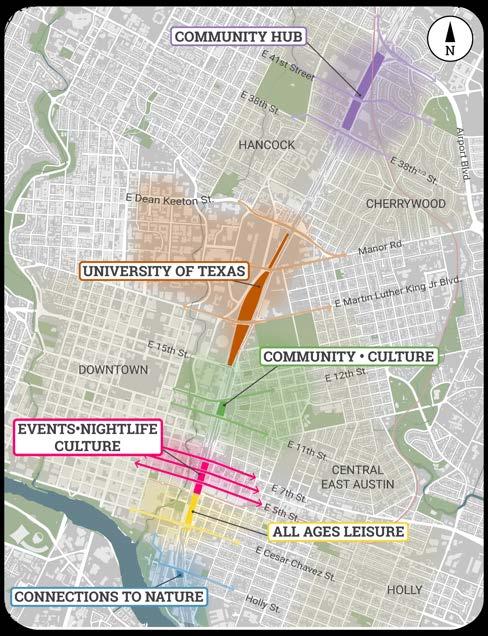


INTENT OF CAP AND STITCH AMENITY CONCEPTS
The illustrative amenity concepts that follow are intended to serve as examples of how the Our Future 35 Vision and Goals and public input regarding desired cap character and amenities may be reflected in cap and stitch designs. These conceptual illustrations are intended to serve as a starting point for future design teams as detailed efforts for individual caps proceed. Future cap designs should meet the desired character as well as the Vision and Goals in this Vision Plan. These cap amenity concepts illustrate potential designs as fully built scenarios. However, on-cap amenities may be phased over time to match funding availability. For example, buildings may take more time to secure funding for than landscape elements and may be phased in after open space features are constructed.
Each of the conceptual illustrations that follow provide plans and sections to illustrate the cap extents and elevations. These have been determined in partnership with TxDOT and will be integrated into the structural design for cap and stitch infrastructure (concrete decks and vertical supports) being led by TxDOT now through 2026. Appendix items provide additional detail regarding structural loading zones and TxDOTapproved access and utility concepts for future amenity designers.
EAST AVENUE TRAIL
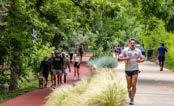
The East Avenue Trail is a proposed north / south running bicycle and pedestrian trail that would serve as a connecting element between each of the caps along the four miles of the Cap and Stitch corridor. It is envisioned as a marquee new component of Austin’s trail infrastructure, connecting users to the Butler Trail at Ladybird Lake and to the proposed Red Line Parkway at Fourth Street and at Airport Boulevard.
The East Avenue Trail is an improvement, or “betterment,” to TxDOT’s planned shared use path (SUP) planned to run along the east side of the I-35 corridor between Lady Bird Lake and 15th Street, then switching sides to run along the west side through Manor Road. Where the planned 10- to 12-foot TxDOT SUP runs adjacent to a cap or stitch, the path may be expanded to a wider trail by using the cap decks for the needed
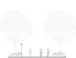
space. This additional cap space allows for a generous trail with separated “lanes” for cyclists and pedestrians as well as robust landscaping and shade.
The proposed name for the trail is culturally significant and derives from the historic East Avenue, the city boulevard that used to run along the I-35 corridor along the edge of East Austin before the construction of the highway in the 1960s. The north/south trail provides opportunities for interpretative nodes along its length, where public art, wayfinding and interpretive signage could highlight the cultural stories and histories of surrounding East Austin neighborhoods and downtown, enriching visitors’ understanding and engagement with the area’s culture and heritage.
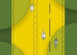
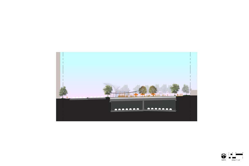
East Avenue Trail Segment Section
East Avenue Trail Segment Plan
EAST AVENUE TRAIL

HOLLY STITCH: CONNECTION TO NATURE
The approximately 300-foot Holly Stitch sits physically between the bustling entertainment district of Rainey Street and the East Cesar Chavez residential neighborhood to the east. It is a unique opportunity to safely connect neighborhood residents with amenities to the west, such as the Emma S. Barrientos Mexican-American Cultural Center, the Butler Hike and Bike Trail and Lady Bird Lake.
DESIRED AMENITY CHARACTER:
Given this stitch’s proximity to Lady Bird Lake, the key connection it will provide to the Butler Trail and the smaller footprint of this deck, the Holly Stitch should provide primarily open space amenities.
POTENTIAL CAP AMENITIES:
Due to the narrower deck structure that must be provided at this location in order to meet TxDOT’s vertical clearance requirements for the roadway beneath, there may not be adequate space for the amount of on-deck fill required to support large shade trees, and trees may need to be accommodated partially within above grade planter boxes.
Potential amenities for this deck include:
• Wildflower gardens/natural space
• Recreational lawn
• Dog park
• Event space
• Public restrooms
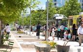
• Space for “pop up” markets
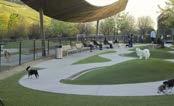
Dog Park and Canopy
Food Trucks
East Avenue Trail

HOLLY STITCH: CONNECTION TO NATURE
HOLLY STITCH: CONNECTION TO NATURE
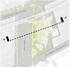
Cross Sections Key Map
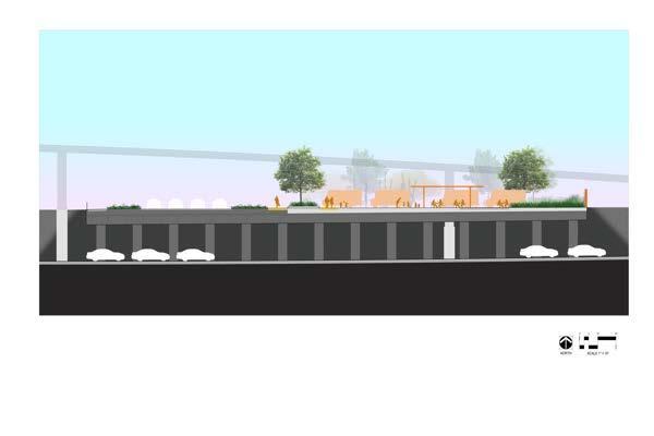
TXDOT MAIN LANES
Holly Stitch Cross Section
CESAR CHAVEZ ST. TO 4TH ST. CAP: ALL AGES LEISURE
This 5.3-acre Cesar Chavez Street to Fourth Street Cap presents an opportunity to connect the East Cesar Chavez Neighborhood to key destinations previously cut off from residents, including the Austin Convention Center, Palm Park and Palm School, and the Waterloo Greenway. The Cesar Chavez Street Cap will create a brand-new pedestrian and bicycle connection at Third Street, linking the East Cesar Chavez Neighborhood to downtown via a new east/west car-free land bridge across the freeway with access unimpeded by frontage road crossings.
DESIRED AMENITY CHARACTER:
The Cesar Chavez Street Cap should provide leisure, sports and recreational uses for families and users of all ages. The Waterloo Greenway Conservancy plans to renovate the adjacent Palm Park to provide children’s playscapes. The Cesar Chavez Cap should provide synergistic recreational daytime uses that attract residents of all ages.
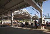

POTENTIAL CAP AMENITIES:
• Sports courts
• Adult “playscapes”/interactive art
• Climbing walls
• Lounge space (such as terraced seating and hammock groves)
• Food vending/concessions
• Cooling stations (such as “misting gardens” or splash pads)
• Bicycle storage and repair station


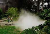
Active Play Canopy
Hammock Grove
Covered Market Space & Dining
Pavilion and Splash Pad
Street Promenade
Mister Garden
CESAR CHAVEZ ST. TO 4TH ST. ALL AGES LEISURE

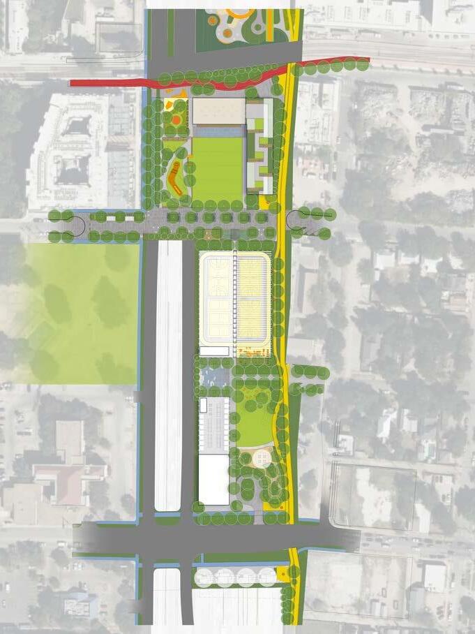


CESAR CHAVEZ ST. TO 4TH ST. ALL AGES LEISURE

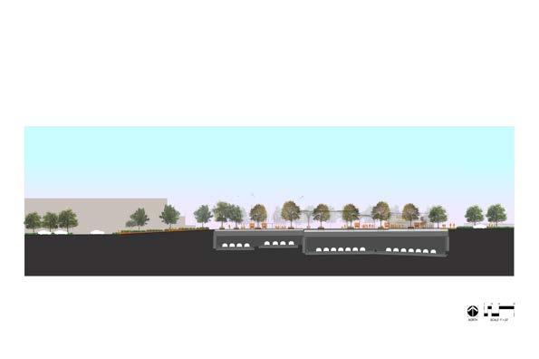


MAIN LANES
Cesar Chavez
Cesar Chavez
4TH ST. TO 7TH ST. CAP: NIGHTLIFE, CULTURE & EVENTS
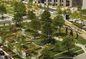
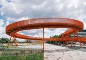
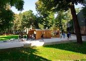
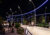
The Fourth Street to Seventh Street Caps are located within the heart of downtown Austin. These caps will connect the active uses east and west along Fifth and Sixth streets, creating a new walkable connection across the highway. This cap will also provide a new connection at Fifth Street for the first time since the 1960s.
DESIRED
AMENITY CHARACTER:
Amenities for this cap should respond to the surrounding nightlife context and provide spaces for food, culture and events for residents and visitors alike.
POTENTIAL CAP AMENITIES:
• Food vending/food courts/restaurants
• Artist market
• Night market
• Event space
• Music performance space/venue
• Cooling stations (such as “misting gardens”)
• Outdoor dining/beer garden
• Small business/artist incubation
• Sculpture garden
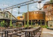
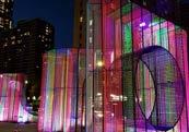
Elevated Walkway & Skateway
Light Features
Sculpture Garden
Outdoor Dining & Venue Space
Pop-Up Spaces
Skating Area
4TH ST. TO 7TH ST.
CAP:
NIGHTLIFE, CULTURE & EVENTS
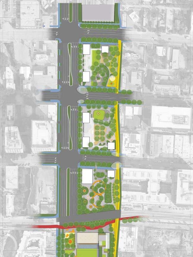

4TH ST. TO 7TH ST. CAP: NIGHTLIFE, CULTURE
& EVENTS


4TH ST. TO 7TH ST. CAP:
CULTURE & EVENTS
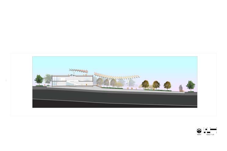
11TH ST. TO 12TH ST. CAP: CULTURE AND COMMUNITY
The 11th Street to 12th Street Cap is a vital opportunity to reconnect East Austin’s vibrant African American business corridors with downtown.
DESIRED AMENITY CHARACTER:
Amenities on the 11th Street to 12th Street Cap should draw from and build upon the African American roots of the surrounding neighborhoods, with amenities serving current and historic residents of the area.

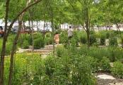
POTENTIAL CAP AMENITIES:
• Cultural spaces
• Outdoor art exhibition space/murals
• Small business/arts incubators
• Public gathering and community spaces
• Resource Center
• Event space
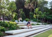
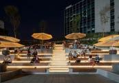


Mural/Exhibition Space
Terraced Seating
Terraced Seating Lighting
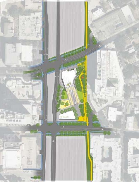
Shaded Paths & Native Plantings Civic Plaza Play Area
11TH ST. TO 12TH ST.
CAP:
CULTURE AND COMMUNITY

11th St. - 12th St. Cap Concept Plan

11TH ST. TO 12TH ST. CAP: CULTURE AND COMMUNITY
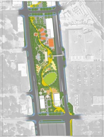
NORTH CAPS: COMMUNITY HUB
The potentia caps between 38th St and Airport Boulevard (approximately 13 acres) are located between the Cherrywood Neighborhood and the Hancock Neighborhood. These caps have substantial opportunity to be integrated into the area’s redevelopment if and when a CapMetro Rail station is added to the Red Line and if and when the Delwood Shopping Center and Hancock Center redevelop. These caps can become a “community hub” and destination for visitors and residents alike.
DESIRED AMENITY CHARACTER:
Amenities for this cap should provide outdoor, recreation and greenspace with a variety of programming for the diverse, mixed-use community surrounding the caps.
POTENTIAL CAP AMENITIES:
• Renewable energy generation
• Cooling stations (such as “misting gardens” or splash pads)
• Gardens
• Adventure park (such as skatepark, climbing walls)
• Multipurpose sports courts
• Picnic Tables
• Play structures
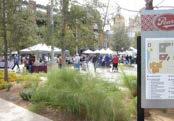
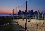


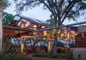
Market Plaza
Picnic Area
Beer Garden
Sports Courts
Dog Park
Adventure Park
NORTH CAPS: COMMUNITY HUB

SOUTHBOUND FRONTAGE ROAD
NORTH CAPS: COMMUNITY HUB
SOUTHBOUND FRONTAGE ROAD
NORTHBOUND FRONTAGE ROAD
INTERPRETATIVE GARDEN CENTER
PAVILION
EAT NODE + MOBILITY HUB
LANES
EAST AVENUE TRAIL
POTENTIAL PEDESTRIAN BRIDGE
NORTHBOUND FRONTAGE ROAD
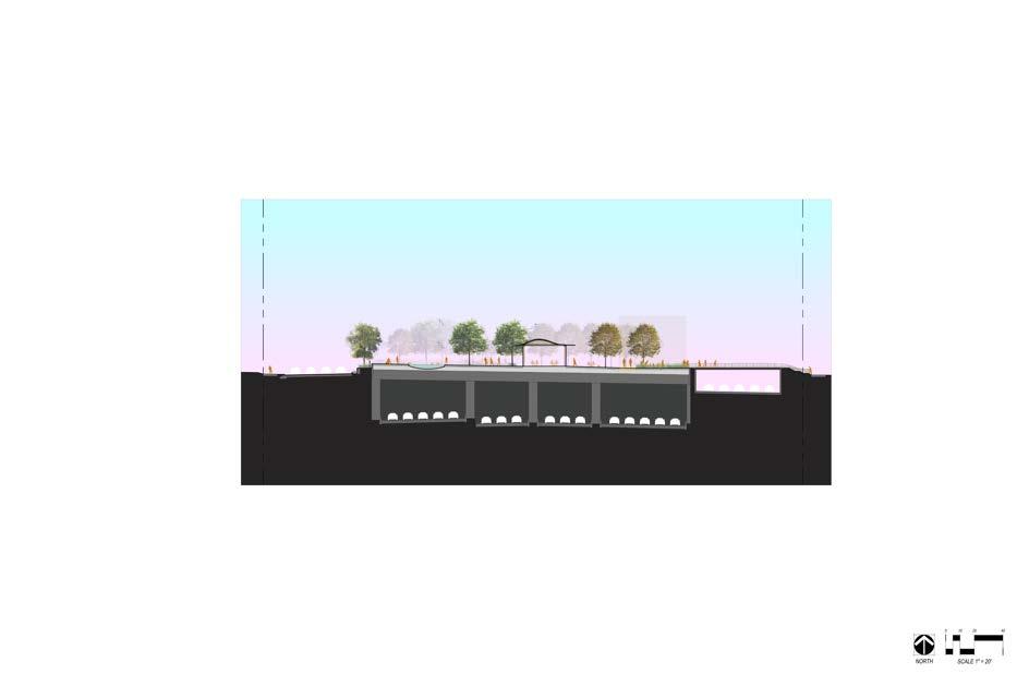

TXDOT MAIN
NORTH CAPS: COMMUNITY HUB


NORTH CAPS: COMMUNITY HUB

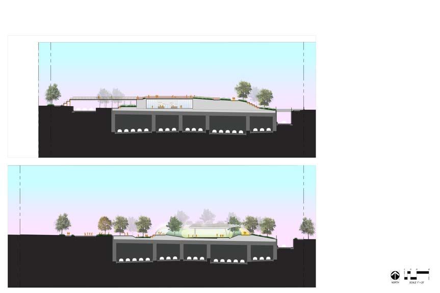
NORTH CAPS: COMMUNITY HUB

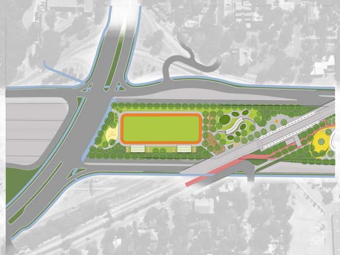
NORTH CAPS: COMMUNITY HUB

DOG PARK PLAZA SHADE STRUCTURE
TXDOT MAIN LANES
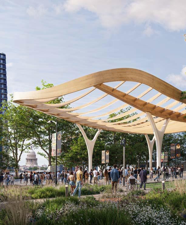
PROJECT
TEXAS DEPARTMENT OF TRANSPORTATION PARTNERSHIP
The design, construction, and operation of caps and stitches over the I-35 highway will be a complex, multi-year effort that will require intergovernmental cooperation, community partnerships and multiple funding sources. Because TxDOT will construct the structural elements for City-funded caps in conjunction with their Capital Express Central Project, design and construction of the elements in this Vision Plan will require close partnership and coordination with TxDOT to meet milestones and avoid delays to the TxDOT project.
While the City continues to develop strategies for funding the various components of the Our Future 35 program, this section of the Vision Plan outlines the general phasing options for funding and constructing caps and stitches over the next several years.

Project Implementation Timeline
CAP AND STITCH PHASING OPTIONS
In general, caps and stitches can be considered as having three distinct components, per Cap Phasing Opportunities graphic on page 47.
• Roadway support elements
• Cap decks
• Surface amenities
The roadway elements (Phase 1) will provide the structural support for the horizontal cap decks, and include structural columns and walls, foundations and fire/life-safety elements that must be embedded within the roadway. Constructing roadway support elements as a first phase preserves the opportunity to build cap decks at a future date as funding becomes available, effectively “future-proofing” the City’s desired caps.
Because many of these structural support elements must be constructed simultaneously with the highway, TxDOT will construct the roadway elements for the City as part of their Capital Express Central Project, anticipated to begin construction in mid-2026 and complete in 2032. This 2026 construction timeline means that the funding for roadway elements must be identified by the City of Austin by the end of 2024 to avoid project delays for CapEx.
Cap decks (Phase 2) are the horizontal structures that span across the highway, on top of which public space amenities are provided. Provided that the roadway elements are funded and in place, the City has a few opportunities to fund and construct cap decks.
The first opportunity would be to integrate the construction of cap decks into TxDOT’s construction process for their Capital Express Central project. This approach would minimize construction disruption for residents and generate some potential cost savings for the City given TxDOT’s planned construction activities for the highway project. If the City procures funding for cap decks by 2027, TxDOT will
incorporate the construction of decks into the Capital Express Central project. Additionally, any caps for which funding is procured by 2032 may be constructed by TxDOT’s contractor through a separate contract. Once TxDOT’s highway construction is substantially complete, the next opportunity for the City to construct cap decks is 2042, the 10-year construction moratorium required by TxDOT upon completion of their highway project.
TxDOT will develop the structural engineering and design of roadway elements and cap decks in 2024-2026 as part of the Capital Express Central highway design to ensure caps and stitches are integrated with the surrounding changes to the roadway. This design work will be completed using City funding committed in December 2023 and additional funding anticipated to be allocated to the structural design work in November 2024.
Generally, the City will construct on-deck surface amenities (Phases 3-5) upon completion of TxDOT’s construction project. Surface amenities themselves may also be constructed in phases as funding is identified. While this Vision Plan identifies fully built-out concepts for caps and stitches, in reality the City may not be prepared financially to fund full buildout of all cap amenities at once, particularly for more expensive elements such as buildings. This may be particularly true for caps that are funded by federal grants, as certain grant funds generally can only be used for “basic amenities” (Phase 3) and any higher-level amenities (Phases 4-5) may require additional funding.
The amenity concepts in this Vision Plan are intended to serve as a starting point for future amenity design teams. The structural loading zones the Structural Loading Report Appendix provide the flexibility future designers will need while also providing the TxDOT structural design teams the technical information required to
CAP AND STITCH PHASING OPTIONS
move forward with design and engineering of the roadway elements and cap decks now. Future amenity designs should include phasing plans that reflect the potential timing of funding available to deliver the desired final build-out of on-cap amenities, including but not limited to buildings on caps.
As plans progress from the concepts shown in the Our Future 35 Vision Plan into the design phase, each cap will go through a community process to refine the recommended amenity package
PHASE 1
Roadway Elements
PHASE 2
Deck and Tunnel Elements
PHASE 3
Minimum Amenities (grass and trees)
and ensure that funding and operations and maintenance needs are met. These programming recommendations will be particularly needed for potential buildings, as the Vision Plan depicts where buildings may be located on the caps structurally but does not include programming recommendations beyond indicating that they may provide spaces for community benefits and services. Funding sources and operator strategies may differ for caps depending on their cap location and context.
PHASE 4
Full Landscaping Amenities
PHASE 5
Buildings
CESAR CHAVEZ STREET TO 4TH STREET CAP IMPLEMENTATION
In Fall 2023 the City applied for US Department of Transportation’s Neighborhood Access & Equity Grant (NAE) for the Cesar Chavez Street to Fourth Street cap and received notice of its winning application in March 2024. The $105.2 million federal award along with the City’s $45 million local match will be applied to the construction of roadway elements, cap decks and amenities for the Cesar Chavez Street to Fourth Street Cap.
The City and TxDOT are currently coordinating on the structural design phase of these caps, including deck alignment, span arrangement, height clearances, structural system, fire/lifesafety systems and retaining walls. Roadway elements and cap decks for the Cesar Chavez Street to Fourth Street Cap will be integrated into TxDOT’s Capital Express Central construction, with these elements currently estimated for completion in 2031.
The City will lead a community process to design the surface amenities for this cap, with the concepts in this Vision Plan serving as the foundation for that work. Construction of oncap amenities is expected to commence upon completion of the deck construction by TxDOT in 2031 and last approximately 1-2 years. As funding is identified for additional cap decks, construction and delivery timelines will be integrated with the TxDOT Capital Express Central project schedule as well.
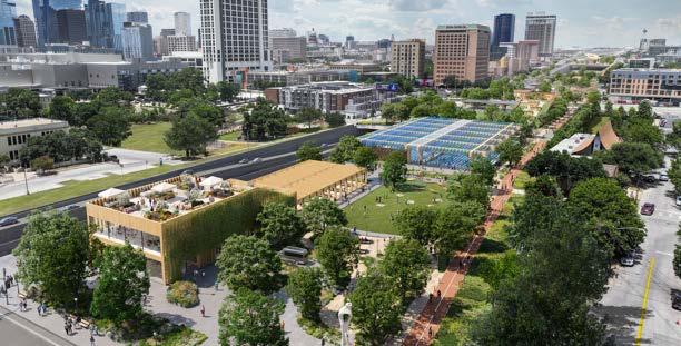
Artist rendering of a cap over I-35 between Cesar Chavez and 4th Street, looking north


Our Future 35 Engagement Report Summary
March 2024 - September 2024
Executive Summary
The "Our Future 35" project, developed by the City of Austin, aims to create new public spaces over Interstate 35 by engaging with community members to ensure the design reflects their needs and connects with their heritage. From March to September 2024, the project ramped up community outreach, utilizing various strategies to engage residents and stakeholders. These included surveys, open houses, and neighborhood outreach events.
Summary of Engagement
The project was initiated in 2020, inspired by discussions surrounding the legacy of segregationist policies in Austin and the impact of I-35 on communities. These discussions eventually led to the formation of the Scoping Working Group, consisting of over 50 organizations, which helped shape the initial vision for the project.
In 2022, the City of Austin began formal community outreach, including surveys and public meetings. The feedback from these efforts contributed to the development of the "Our Future 35 Vision Plan" and the establishment of the Community Steering Committee (CSC). Since then, the City has continued its engagement with stakeholders, including local businesses, residents, cultural institutions, and community leaders, in a series of interviews, workshops, and open houses.
2024 Engagement Efforts
The 2024 engagement strategy focused on two primary approaches: widespread outreach via digital and print media, and grassroots efforts to connect with individuals in their neighborhoods. The goal was to ensure that community voices were central to the design of new public spaces over I-35.
Open Houses and Survey Insights
• Open House (May 18, 2024): Introduced initial cap and stitch concepts to the public, with around 400 attendees. A total of 280 surveys were collected (200 digital, 80 paper).
• Business- Oriented Open House (May 21, 2024): A smaller event aimed at business stakeholders, with 20 attendees.
• Survey Launch: The survey was offered in the eight most-used languages1 in Austin, and it aimed to gather feedback on the Vision Plan and cap concepts. A total of 1,783 responses were collected, providing key insights into public preferences for cap design and amenities.
1 English, Spanish, Simplified Chinese, Vietnamese, Korean, Arabic, French, Hindi, as defined by 2020 U.S. Census data
Key Survey Results:
• 73% of respondents identified as White, with smaller percentages identifying as Hispanic, Asian, Black, and Native/Indigenous.
• 79% of respondents supported the draft vision and goals.
• The top five desired amenities were recreational lawn space, pollinator gardens, food vending, event spaces, and public art.
Continued Engagement: June-August 2024
To sustain momentum from the May open house, the city conducted an extensive summer outreach campaign. This included media promotions, direct mailing to residents near I-35, an internal City of Austin employee survey contest, and in-person tabling at community events. A total of 28 events were held, engaging over 1,000 community members across various neighborhoods.
In August, the city hosted a series of workshops to refine the cap and stitch concepts based on initial feedback. These workshops involved key community stakeholders and organizations, providing additional opportunities for dialogue.
September Open House and Next Steps
A final open house in September concluded the summer engagement period. More than 320 individuals attended the event showcasing community-informed revised concepts for the potential caps and stitches. The event was held at Canopy Austin.
Sustained engagement is planned as the project progresses, especially in preserving trust with communities that have historically been underserved. The next focus of engagement efforts will be to design funded elements of the project, such as the cap that will span Cesar Chavez to Fourth streets.
Timeline of Key Events
• 2020: Formation of the "Our Future 35" project, inspired by discussions on segregationist policies and the impact of I-35.
• Fall 2022: Open house and survey to shape the Vision Plan.
• March 2024: Promotion begins for the May open house.
• May 10, 2024: Visioning survey launches.
• May 18, 2024: First public open house with 350-400 attendees; 280 surveys collected.
• May 21, 2024: Business- oriented open house with 20 attendees.
• June 3-August 5, 2024: Extensive outreach efforts, including postcard mailings, tabling at community events, and targeted advertisements.
• August 2024: Workshops held to refine cap concepts, focusing on neighborhood-specific needs and feedback.
• September 2024: Final open house held. Vision Plan scheduled for presentation to City Council in November 2024.
Appendices
• Appendix A: Vision and Goals of the Our Future 35 Project.
• Appendix B: Engagement Timeline (May-December 2024).
• Appendix C: Media Coverage from local outlets on the project from May-September 2024.
Appendix A: Vision and Goals of the Our Future 35 Project

Vision:
The "Our Future 35" project envisions transforming the I-35 highway corridor into a network of vibrant, inclusive, and accessible public spaces that reconnect historically divided communities in Austin. The project aims to repair the social and economic damage caused by the original construction of the highway and offer new opportunities for community building, economic development, and public recreation.
Goals:
1. Community Connectivity:
o Build infrastructure that physically and socially reconnects neighborhoods divided by I-35, particularly those in historically marginalized areas. The new spaces should create seamless links across both sides of the highway.
o Focus on creating pedestrian-friendly bridges, green spaces, and public squares that foster interaction among residents.
2. Green Space and Recreation:
o Maximize green areas, with a goal of ensuring that at least 75% of cap areas are dedicated to parks, recreational spaces, and nature.
o Design these spaces to support a variety of activities, from relaxation to active recreation, for all age groups.
o Encourage environmentally sustainable practices, including the use of native plants, stormwater management systems, and pollution reduction techniques.
3. Cultural Preservation and Engagement:
o Honor the rich cultural histories of the neighborhoods surrounding I-35, especially Black and Hispanic communities in East Austin, by integrating public art, historical markers, and community events that reflect their stories and traditions.
o Create spaces that support cultural festivals, markets, and community gatherings.
4. Inclusive Economic Development:
o Promote economic growth that benefits residents and small businesses, focusing on providing affordable retail space, food vending areas, and spaces for local markets and business incubators.
o Ensure that economic benefits generated by new developments, such as restaurants, cafes, and event spaces, flow back into the local community through job creation and investment opportunities.
5. Sustainability and Environmental Justice:
o Incorporate environmentally conscious designs that address pollution, reduce vehicle emissions, and promote the use of clean energy and materials.
o Prioritize the needs of historically marginalized communities that have borne the brunt of I-35’s environmental impacts, ensuring their voices are centered in the decision-making process.
6. Accessibility, Equity, and Safety:
o Design spaces that are fully accessible to people of all abilities, with a particular emphasis on ADA- compliant walkways, clear signage, and safe, well-lit pedestrian areas.
o Ensure these spaces are safe for children, families, and the elderly by integrating features such as playgrounds, gathering areas, and shaded seating.
o Integrate public safety measures, including clear sightlines, regular police patrols, and the inclusion of emergency call systems.
Appendix B: Detailed Engagement Timeline
(March - December 2024)
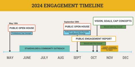
March 2024:
• Open House Promotion: The City of Austin began promoting the May open house using digital ads, newsletters, and media coverage. Outreach focused on targeting residents, business owners, and local organizations.
o Media Channels:
Digital ads on Facebook, Instagram, and mobile platforms.
Print ads in local newspapers including AustinAmerican-Statesman, CommunityImpact, AustinMonitor, ElMundo(Spanish) and TheVillager.
Broadcast segments on KUT, KUTX, KVUE, KXAN, CW Austin, Waterloo Media (multiple radio stations and digital, English and Spanish) and Univision
Over-the-street banners at nine locations across Austin
May 2024:
• May 10, 2024:
o Visioning Survey Launch: A community-wide survey was made available in eight languages to collect feedback on the draft Vision Plan and initial cap concepts. The goal was to gather data on community preferences for cap amenities and space
usage. Survey available in: English, Spanish, Simplified Chinese, Vietnamese, Korean, Arabic, French, and Hindi.
• May 18, 2024:
o Public Open House: Held at Austin Community College’s Highland Campus, the open house introduced the public to initial cap and stitch concepts.
Attendees: Approximately 350-400 community members attended.
Surveys Collected: 280 surveys were submitted (200 digital, 80 paper).
Event Coverage: Covered by Fox 7, KXAN, KUT and other local news outlets.
• May 21, 2024:
o Business- Oriented Open House: A separate open house was held for business owners at the Austin Central Library.
Attendees: 20 business representatives attended to provide feedback on the cap design’s potential impacts on local commerce and economic development.
June - August 2024:
• June 3 - August 5, 2024:
o Summer Stakeholder and Community Outreach: The City of Austin intensified its efforts to engage residents through postcard mailings, digital ads, an employee survey contest, and in-person outreach at local events.
Postcard Mailings: Sent to roughly 25,000 residents in underrepresented communities as well as properties within a quarter mile of I-35.
Employee Contest: City departments competed in a survey challenge, with Austin Public Library winning the prize.
In-Person Tabling: Staff attended 28 community events (listed in table on next page) across all Austin City Council districts, meeting residents where they live and gathering more direct feedback.
Juneteenth Park Festival
Conley-Guerrero Senior Center
Party at the People’s House
Northwest Recreation Center
Dittmar Recreation Center
June 15 District 1
June 20 District 1
June 22 District 9
June 24 District 7
June 24 District 2
Barton Springs Pool June 26 District 8
DAC Nights, Dougherty Arts Center June 26 District 9
Austin Asian American Film Festival June 28 District 4
Old Bakery and Emporium Midsummer Festival
June 29 District 9
Big Stacy Pool July 3 District 9
North Loop Neighborhood HOA July 3 District 9
Milwood Neighborhood HOA
Mobile Vaccine Clinic: El Buen Samaritano
July 4 District 7
July 9 District 5
Pan AM Hillside Concert Series July 9 District 3
Montopolis Recreation Center
Del Valle Community Coalition Mobile Vaccine Clinic
East Cesar Chavez Neighborhood Association
July 11 District 3
July 13 Del Valle
July 17 District 3
Hancock Neighborhood HOA July 17 District 9
Gus Garcia Recreation Center
July 17 District 4
Asian American Resource Center July 17 District 1
AACHI Annual Health Fair July 20 District 1
Si se Puede: Road to Leadville Screening at the Dougherty Arts Center July 21 District 9
Bull Creek Foundation and Neighborhood HOA July 27 District 6
Scofield Ridge Homeowners Association July 27 District 7
UT Free Furniture Market July 27 District 9
Texas Mueller Farmer’s Market July 28 District 9
AVAMPS Mobile Vaccine Clinic
July 30 District 4
Dove Springs Recreation Center Back to School Bash August 3 District 2
Survey Insights
The Our Future 35 visioning survey closed on August 2. A total of 1,783 individuals responded to the survey. A full report on the survey insights will be made available in late 2024. 1,088 respondents reported demographic data.
• 73.44% (799 respondents) identified as White/Caucasian.
• 15.90% (173 respondents) identified as Hispanic and/or Latino/Latina/Latinx.
• 7.44% (81 respondents) identified as Asian.
• 5.61% (61 respondents) identified as Black and/or African American.
• 3.31% (36 respondents) identified as Other.
• 2.48% (27 respondents) identified as Native/Indigenous.
The survey provided the draft Vision and Goals as well as preliminary cap concepts for public feedback. Of the 1,783 respondents, 79.30% (1,387 respondents) supported the draft vision and goals,12.64% (221) respondents were unsure, and 8.06% (141 respondents) did not support.
Respondents preferred 25% buildings to 75% greenspace ratio for every cap. Acrosstheentirecap system,the top 5 amenities were:
• Recreational lawn space
• Pollinator gardens
• Food hall/food vending/farmers markets
• Event space, and
• Public art
Tying it All Together: Engagement Map, May 18-August 5th
• The map on the next page shows the locations where staff spoke with community members in-person between May 18 and August 5, including the May Open House. The summer stakeholder and community outreach program engaged with an estimated 1,033 people.

August 2024:
• Workshops for Specific Caps: Community workshops were held to gather detailed feedback on specific cap locations.
o Holly Street - Seventh Street Caps (August 19, 2024): Focused on greenspace and dog parks, as well as food truck access and pedestrian safety.
o 11th - 12th Street Cap (August 20, 2024): Discussions centered on accessibility, preserving Black cultural heritage, and creating gathering spaces.
o 38½ Street - Airport Boulevard Caps (August 15, 2024): Focused on reducing noise and traffic pollution, greenspace needs, and potential library branch integration.
• August 22, 2024:
o Listening Session for 11th - 12th Street Cap: A session initiated by former Steering Committee member Kenneth Thompson to address community concerns about the project’s impact on East Austin.
• August 23, 2024:
o Technical Advisory Committee (TAC) Drop -In Session: Attended by 25 city staff members and key representatives from the community. Feedback from this session will inform September designs.
• Final Open House Promotion
o Paid Advertising: KXAN, CW Austin, Austin Monitor, Community Impact, Univision, Spectrum, KUT/KUTX, Soulciti, Waterloo Media (multiple radio stations), The Villager, El Mundo, Austin American-Statesman
o Social Media Ads
o Organic Social Media Posts
o Geotargeted Digital Ads
o CTV/OTT
o Media Advisory
Fall 2024:
• September 28, 2024:
o Final Open House: Held to present the revised cap and stitch designs based on the feedback gathered throughout the summer. The refined Vision Plan and proposed full-build concepts were discussed, and further public input was solicited.
Attendees: Approximately 325 community members attended.
Comments Received: 90 hand-written comment cards received.
Event Coverage: Covered by KVUE and local news outlets.
• November 7, 2024:
o Presentation to Austin City Council: City executives will present the Our Future 35 Vision Plan, including cap designs, development strategies, and funding needs.
• December 2024: Potential Funding Vote: Austin City Council will vote on whether to commit funds to begin construction on the highway caps.
Appendix C:
Media Coverage (May - September 2024)
Key Articles and Coverage:
1. Planetizen (May 1, 2024):
o AustinSeeksFederalGrantsforFreewayCapsasI-35ExpansionPlanMoves Forward: This article discusses Austin's pursuit of $124 million in federal funds to support the construction of highway caps over I-35 as part of the larger expansion project.
2. Austin American-Statesman (May 1, 2024):
o AustinMaySeek$124MFederalGrantfor'Cap'ProgramforDecksOverLoweredI35: This piece explores Austin's bid for federal funding and the significance of the cap -and-stitch program in reconnecting communities.
3. Austin Monitor/KUT (May 13, 2024):
o UTApprovesI-35Cap-and-StitchFunding: Covers the University of Texas at Austin’s financial commitment to funding a portion of the cap project.
4. KVUE (May 14, 2024):
o UTAustinApproves$13.5MDeposittoBuildCapAcrossaPortionofI-35: Reports on the University’s significant financial contribution toward building caps over the highway.
5. KXAN (May 15, 2024):
o AustinAwarded$75KGrantforArtisttoAidinHighwayCoveringsProgram: Highlights a grant awarded to an artist who will help design highway coverings as part of the I-35 cap project.
6. CBS Austin (May 18, 2024):
o OurFuture35OpenHouseGatherstheCommunitytoShareVisiononFourCaps: Provides a recap of the open house event and community feedback on proposed cap designs.
7. KUT/KERA (August 6, 2024):
o WhatCanAustinLearnfromDallasAboutCoveringI-35withaPark?: A comparative look at how Austin can learn from Dallas’ successes and challenges in constructing parks over highways.
Additional Media Coverage:
• Austin Stitched Together: A Divisive Legacy Lingers as I-35 Expands (KXAN, May 21, 2024).
• Highway Coverings Are Coming to Austin. Here’s How to Weigh in on Design Work (KXAN, June 18, 2024).
• Our Future 35 and Your Chance to Shape the City You Call Home (Audacy Podcast, July 7, 2024).
• TxDOT Rolls Out I-35 Project Design Changes at Airport Boulevard Intersection (KXAN, August 2, 2024).
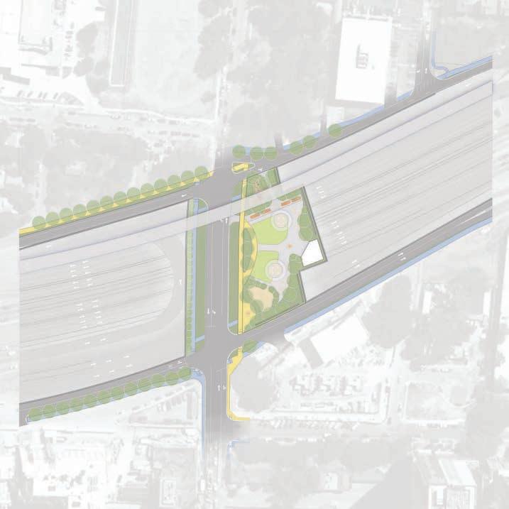
Downtown Caps
Holly Street | Ped/Bike Access
Downtown Caps
Holly Street | Fire/EMS and Service Access
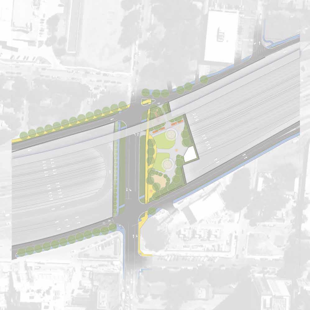
Holly Street
Downtown Caps
Cesar Chavez to 4th Street | Ped/Bike Access

Cap/Stitch Buildings
Ped/Bike Access Route Primary Cap Entry/Exit Points
Downtown Caps
Cesar Chavez to 4th Street | Fire/EMS and Service Access

Downtown Caps
4th to 7th Street | Ped/Bike Access

Cap/Stitch Buildings
Ped/Bike Access Route Primary Cap Entry/Exit Points
Downtown Caps
4th to 7th Street | Fire/EMS and Service Access

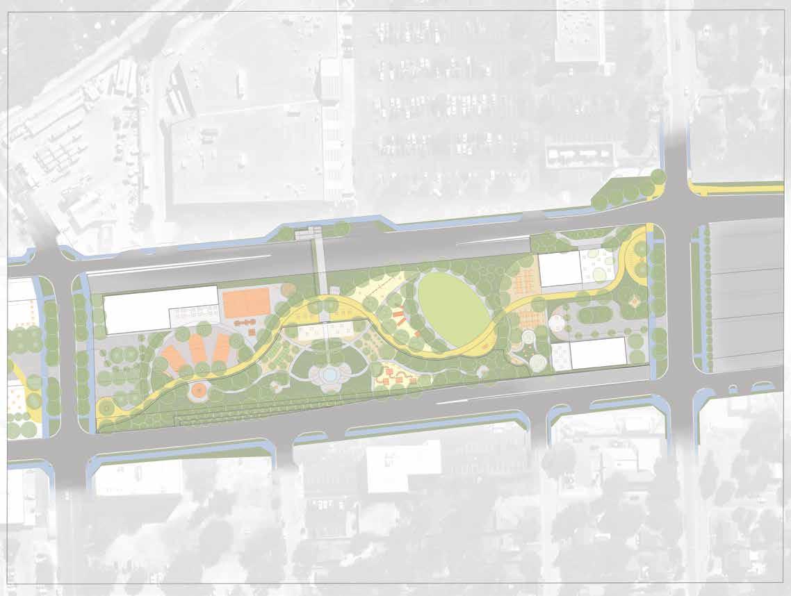
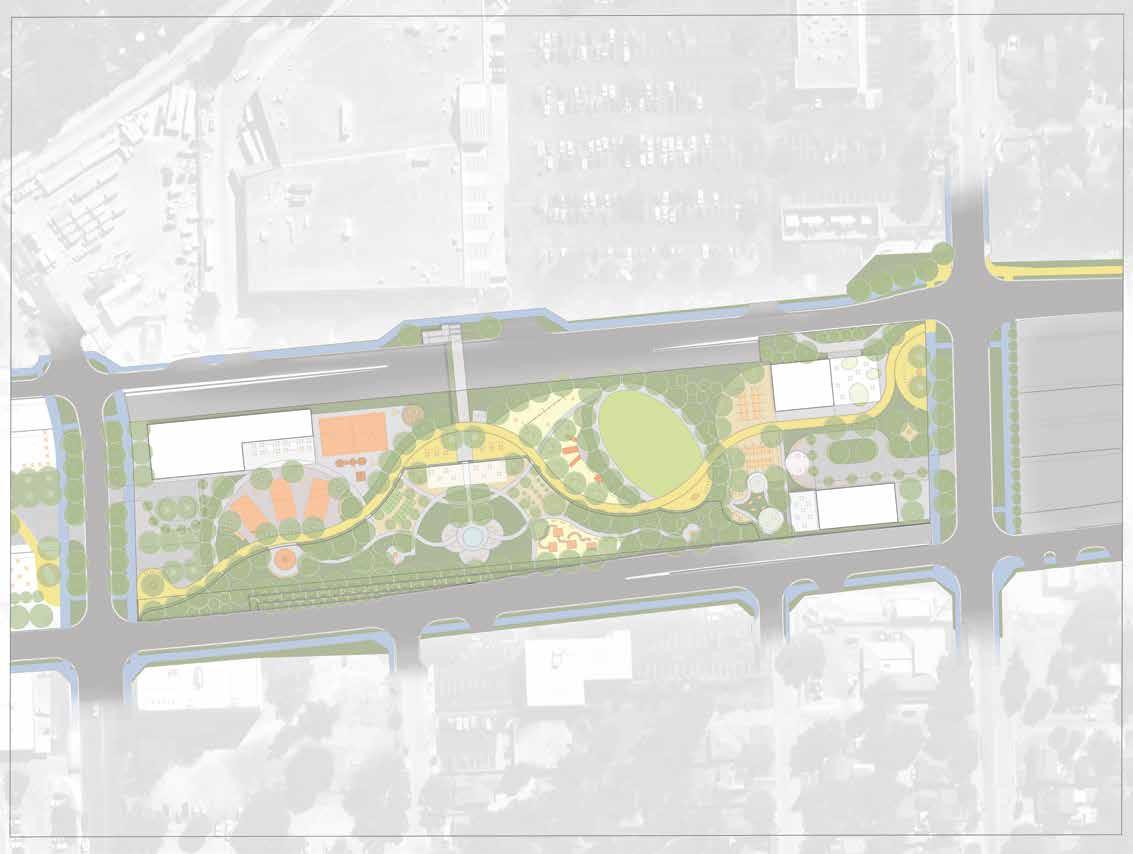
Downtown Caps
11th to 12th Street | Ped/Bike Access

Cap/Stitch Buildings
Ped/Bike Access Route
Cap Entry/Exit Points

41st Street to Redline | Ped/Bike Access
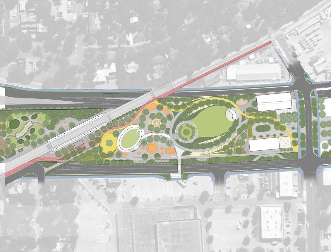
CapMetroRedline

CapMetroRedline
Northern Caps
Redline to Airport Boulevard | Ped/Bike Access
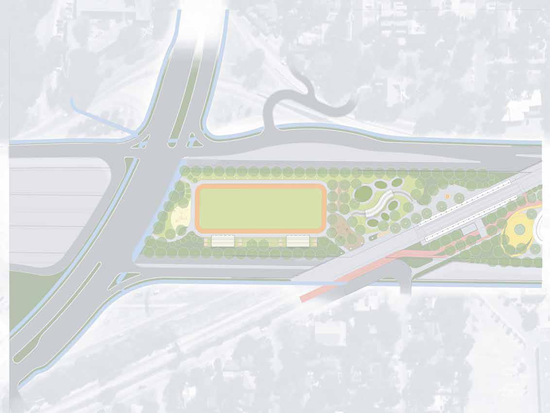
Airport Boulevard
Legend
Cap/Stitch Buildings
Ped/Bike Access Route
Primary Cap Entry/Exit Points
CapMetroRedline
potentialpedestrianbridge
Northern Caps
Redline to Airport Boulevard | Fire/EMS and Service Access

CapMetroRedline
potentialpedestrianbridge


NOTES:
1. CONCEPTUAL GRADING SECTIONS SHOWN HEREIN ARE REFLECTIVE OF DESIGN CONCEPTS FOR CAP AND STITCH AS OF 10/25/2024. FINAL DESIGN FOR PROGRAMMING MAY VARY.
2. ALL TOP OF CAP (TOC) ELEVATIONS INCLUDE 2' OF CAP PROGRAMMING UNLESS NOTED OTHERWISE.
3. TOP OF BERM (TOB) ELEVATIONS ARE RELATIVE TO AND FOLLOW THE SLOPE OF TOP OF CAP.
4. TOP OF PLATFORM (TOP) ELEVATIONS ARE CONSTANT ACROSS THE AREA OF PLATFORM UNLESS NOTED OTHERWISE.
5. TOP OF STRUCTURE (TOS) ELEVATIONS ARE MAXIMUMS.
6. ADDITIONAL GEOFOAM FILL IS REQUIRED WHERE INCOMPATIBILITY BETWEEN DECK AND PROGRAMMING SLOPES EXIST. SLOPE OF PROGRAMMING IS 0%.


NOTES:
1. CONCEPTUAL GRADING SECTIONS SHOWN HEREIN ARE REFLECTIVE OF DESIGN CONCEPTS FOR CAP AND STITCH AS OF 10/25/2024. FINAL DESIGN FOR PROGRAMMING MAY VARY.
2. ALL TOP OF CAP (TOC) ELEVATIONS INCLUDE 4' OF CAP PROGRAMMING UNLESS NOTED OTHERWISE.
3. TOP OF BERM OR TRENCH (TOB, TOT) ELEVATIONS ARE RELATIVE TO AND FOLLOW THE SLOPE OF TOP OF CAP. 4. TOP OF PLATFORM (TOP) ELEVATIONS ARE CONSTANT ACROSS THE AREA OF PLATFORM UNLESS NOTED OTHERWISE.
5. TOP OF STRUCTURE (TOS) ELEVATIONS ARE MAXIMUMS.
6. ADDITIONAL GEOFOAM FILL IS REQUIRED WHERE INCOMPATIBILITY BETWEEN DECK AND PROGRAMMING SLOPES EXIST. SLOPE OF PROGRAMMING BETWEEN CC AND 3RD STREET IS 0%.


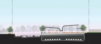


NOTES:
1. CONCEPTUAL GRADING SECTIONS SHOWN HEREIN ARE REFLECTIVE OF DESIGN CONCEPTS FOR CAP AND STITCH AS OF 10/25/2024. FINAL DESIGN FOR PROGRAMMING MAY VARY.
2. ALL TOP OF CAP (TOC) ELEVATIONS INCLUDE 4' OF CAP PROGRAMMING UNLESS NOTED OTHERWISE.
3. TOP OF BERM (TOB) ELEVATIONS ARE RELATIVE TO AND FOLLOW THE SLOPE OF TOP OF CAP.
4. TOP OF PLATFORM (TOP) ELEVATIONS ARE CONSTANT ACROSS THE AREA OF PLATFORM UNLESS NOTED OTHERWISE.
5. TOP OF STRUCTURE (TOS) ELEVATIONS ARE MAXIMUMS.


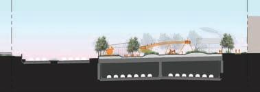


NOTES:
1. CONCEPTUAL GRADING SECTIONS SHOWN HEREIN ARE REFLECTIVE OF DESIGN CONCEPTS FOR CAP AND STITCH AS OF 10/25/2024. FINAL DESIGN FOR PROGRAMMING MAY VARY.
2. ALL TOP OF CAP (TOC) ELEVATIONS INCLUDE 4' OF CAP PROGRAMMING UNLESS NOTED OTHERWISE.
3. TOP OF BERM OR TRENCH (TOB, TOT) ELEVATIONS ARE RELATIVE TO AND FOLLOW THE SLOPE OF TOP OF CAP.
4. TOP OF PLATFORM (TOP) ELEVATIONS ARE CONSTANT ACROSS THE AREA OF PLATFORM UNLESS NOTED OTHERWISE.
5. TOP OF STRUCTURE (TOS) ELEVATIONS ARE MAXIMUMS.
6. ADDITIONAL GEOFOAM FILL IS REQUIRED WHERE INCOMPATIBILITY BETWEEN DECK AND PROGRAMMING SLOPES EXIST.


POTENTIAL PEDESTRIAN BRIDGE


NOTES:
1. CONCEPTUAL GRADING PLANS SHOWN HEREIN ARE REFLECTIVE OF DESIGN CONCEPTS FOR CAP 10/25/2024. FINAL DESIGN FOR PROGRAMMING MAY VARY.
2. ALL TOP OF CAP (TOC) ELEVATIONS INCLUDE 4' OF CAP PROGRAMMING UNLESS NOTED OTHERWISE.
3. TOP OF BERM OR TRENCH (TOB, TOT) ELEVATIONS ARE RELATIVE TO AND FOLLOW THE SLOPE
4. TOP OF PLATFORM (TOP) ELEVATIONS ARE CONSTANT ACROSS THE AREA OF PLATFORM UNLESS 5. TOP OF STRUCTURE (TOS) ELEVATIONS ARE MAXIMUMS.


NOTES:
1. CONCEPTUAL GRADING SECTIONS SHOWN HEREIN ARE REFLECTIVE OF DESIGN CONCEPTS FOR CAP AND STITCH AS OF 10/25/2024. FINAL DESIGN FOR PROGRAMMING MAY VARY.
2. ALL TOP OF CAP (TOC) ELEVATIONS INCLUDE 4' OF CAP PROGRAMMING UNLESS NOTED OTHERWISE.
3. TOP OF BERM OR TRENCH (TOB, TOT) ELEVATIONS ARE RELATIVE TO AND FOLLOW THE SLOPE OF TOP OF CAP.
4. TOP OF PLATFORM (TOP) ELEVATIONS ARE CONSTANT ACROSS THE AREA OF PLATFORM UNLESS NOTED OTHERWISE.
5. TOP OF STRUCTURE (TOS) ELEVATIONS ARE MAXIMUMS.


CAPMETROREDLINE
NOTES:
1. CONCEPTUAL GRADING PLANS SHOWN HEREIN ARE REFLECTIVE OF DESIGN CONCEPTS FOR CAP AND STITCH AS OF 10/25/2024. FINAL DESIGN FOR PROGRAMMING MAY VARY.
2. ALL TOP OF CAP (TOC) ELEVATIONS INCLUDE 4' OF CAP PROGRAMMING UNLESS NOTED OTHERWISE.
3. TOP OF BERM (TOB) ELEVATIONS ARE RELATIVE TO AND FOLLOW THE SLOPE OF TOP OF CAP.
4. TOP OF PLATFORM (TOP) ELEVATIONS ARE CONSTANT ACROSS THE AREA OF PLATFORM UNLESS NOTED OTHERWISE.
5. TOP OF STRUCTURE (TOS) ELEVATIONS ARE MAXIMUMS.
DECK DRAINAGE FLOW DIRECTION. PROGRAMMING SLOPE TO MATCH DECK SLOPE.
POTENTIAL PEDESTRIAN BRIDGE


NOTES:
1. CONCEPTUAL GRADING SECTIONS SHOWN HEREIN ARE REFLECTIVE OF DESIGN CONCEPTS FOR CAP AND STITCH AS OF 10/25/2024. FINAL DESIGN FOR PROGRAMMING MAY VARY.
2. ALL TOP OF CAP (TOC) ELEVATIONS INCLUDE 4' OF CAP PROGRAMMING UNLESS NOTED OTHERWISE.
3. TOP OF BERM (TOB) ELEVATIONS ARE RELATIVE TO AND FOLLOW THE SLOPE OF TOP OF CAP.
4. TOP OF PLATFORM (TOP) ELEVATIONS ARE CONSTANT ACROSS THE AREA OF PLATFORM UNLESS NOTED OTHERWISE.
5. TOP OF STRUCTURE (TOS) ELEVATIONS ARE MAXIMUMS.
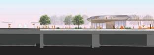


POTENTIAL PEDESTRIAN


NOTES:
1. CONCEPTUAL GRADING SECTIONS SHOWN HEREIN ARE REFLECTIVE OF DESIGN CONCEPTS FOR CAP AND STITCH AS OF 10/25/2024. FINAL DESIGN FOR PROGRAMMING MAY VARY.
2. ALL TOP OF CAP (TOC) ELEVATIONS INCLUDE 4' OF CAP PROGRAMMING UNLESS NOTED OTHERWISE.
3. TOP OF BERM (TOB) ELEVATIONS ARE RELATIVE TO AND FOLLOW THE SLOPE OF TOP OF CAP.
4. TOP OF PLATFORM (TOP) ELEVATIONS ARE CONSTANT ACROSS THE AREA OF PLATFORM UNLESS NOTED OTHERWISE.
5. TOP OF STRUCTURE (TOS) ELEVATIONS ARE MAXIMUMS.


NOTES:
1. CONCEPTUAL GRADING SECTIONS SHOWN HEREIN ARE REFLECTIVE OF DESIGN CONCEPTS FOR CAP AND STITCH AS OF10/25/2024. FINAL DESIGN FOR PROGRAMMING MAY VARY.
2. ALL TOP OF CAP (TOC) ELEVATIONS INCLUDE 4' OF CAP PROGRAMMING UNLESS NOTED OTHERWISE.
3. TOP OF BERM (TOB) ELEVATIONS ARE RELATIVE TO AND FOLLOW THE SLOPE OF TOP OF CAP.
4. TOP OF PLATFORM (TOP) ELEVATIONS ARE CONSTANT ACROSS THE AREA OF PLATFORM UNLESS NOTED OTHERWISE.
5. TOP OF STRUCTURE (TOS) ELEVATIONS ARE MAXIMUMS.
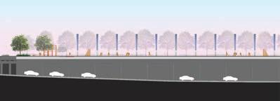
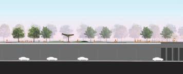


AMENITYUTILITYSERVICENEEDS:
· BUILDING F/W/E/T/WW
· DOGPARK W/WW
· COOLINGSTA. F/W/E
· OPENSPACE W/E
· LIGHTING E
PROPOSEDON-CAP UTILITYCORRIDOR:
-WATER(FIRE) -WATER(DOMESTIC) -ELECTRIC -TELECOM -WASTEWATER
NOTES:
1.UTILITYCORRIDORS/SERVICECONNECTIONSANDAMENITIES/SERVICENEEDSAS SHOWNHEREINARENOTINTENDEDTOBECOMPREHENSIVENORPRESCRIPTIVE. UTILITYTYPES,SIZE/MATERIAL,LOCATIONS,ANDROUTINGTOBEADJUSTEDAS NEEDEDINLATERDESIGNPHASESPERFINALON-CAPPROGRAMMING.
2.PROPOSEDON-CAPUTILITIESTOBEROUTEDABOVETXDOTSTRUCTURALSLAB. REFERTOCONCEPTUALUTILITYCROSSSECTIONINREPORT.
3.CAPANDSTITCHPROJECTSHALLCOORDINATEWITHAUSTINWATERFOR POTENTIALRECLAIMEDWATERROUTINGINFUTUREDESIGNPHASE.
4.CAPDRAINAGETOBEROUTEDTOTXDOT-PROVIDEDDECKDRAINS&DRAINAGE SYSTEM.REFERTOCONCEPTUALDRAINAGEAXONSECTIONINREPORT.
LeadConsultant
SubConsultant


CONCEPTUALUTILITYPLANHOLLYSTREETSTITCH
WASTEWATER Legend
WATER(FIRE) WATER(DOMESTIC) ELECTRIC TELECOM
· AMENITYUTILITYSERVICENEEDS:
· BUILDINGS F/W/E/T/WW
· PAVILION F/W/E
· RESTROOMS F/W/E/WW
· FOODKIOSK F/W/E/WW
· COOLINGSTA. F/W/E
· OPENSPACE W/E
· LIGHTING E
PROPOSEDON-CAP UTILITYCORRIDOR: -WATER(FIRE) -WATER(DOMESTIC) -ELECTRIC -TELECOM -WASTEWATER
NOTES:
1.UTILITYCORRIDORS/SERVICECONNECTIONSANDAMENITIES/SERVICENEEDSAS SHOWNHEREINARENOTINTENDEDTOBECOMPREHENSIVENORPRESCRIPTIVE. UTILITYTYPES,SIZE/MATERIAL,LOCATIONS,ANDROUTINGTOBEADJUSTEDAS NEEDEDINLATERDESIGNPHASESPERFINALON-CAPPROGRAMMING.
2.PROPOSEDON-CAPUTILITIESTOBEROUTEDABOVETXDOTSTRUCTURALSLAB. REFERTOCONCEPTUALUTILITYCROSSSECTIONINREPORT.
3.CAPANDSTITCHPROJECTSHALLCOORDINATEWITHAUSTINWATERFOR POTENTIALRECLAIMEDWATERROUTINGINFUTUREDESIGNPHASE.
4.CAPDRAINAGETOBEROUTEDTOTXDOT-PROVIDEDDECKDRAINS&DRAINAGE SYSTEM.REFERTOCONCEPTUALDRAINAGEAXONSECTIONINREPORT.


WATER(FIRE) WATER(DOMESTIC) ELECTRIC TELECOM WASTEWATER Legend
CONCEPTUALUTILITYPLANCESARCHAVEZTO4THCAPS (INCL.SOUTHCAPEXTENSION)
PROPOSEDON-CAP UTILITYCORRIDOR: -WATER(FIRE) -WATER(DOMESTIC) -ELECTRIC
· AMENITYUTILITYSERVICENEEDS:
· BUILDINGS F/W/E/T/WW
· DOGPARK W/WW
· COOLINGSTA. F/W/E
· OPENSPACE W/E
· LIGHTING E
PROPOSEDON-CAP UTILITYCORRIDOR: -WATER(FIRE) -WATER(DOMESTIC) -ELECTRIC -TELECOM -WASTEWATER
NOTES:
1.UTILITYCORRIDORS/SERVICECONNECTIONSANDAMENITIES/SERVICENEEDSAS SHOWNHEREINARENOTINTENDEDTOBECOMPREHENSIVENORPRESCRIPTIVE. UTILITYTYPES,SIZE/MATERIAL,LOCATIONS,ANDROUTINGTOBEADJUSTEDAS NEEDEDINLATERDESIGNPHASESPERFINALON-CAPPROGRAMMING.
2.PROPOSEDON-CAPUTILITIESTOBEROUTEDABOVETXDOTSTRUCTURALSLAB. REFERTOCONCEPTUALUTILITYCROSSSECTIONINREPORT.
3.CAPANDSTITCHPROJECTSHALLCOORDINATEWITHAUSTINWATERFOR POTENTIALRECLAIMEDWATERROUTINGINFUTUREDESIGNPHASE.
4.CAPDRAINAGETOBEROUTEDTOTXDOT-PROVIDEDDECKDRAINS&DRAINAGE SYSTEM.REFERTOCONCEPTUALDRAINAGEAXONSECTIONINREPORT.


WATER(FIRE) WATER(DOMESTIC) ELECTRIC TELECOM WASTEWATER Legend
· AMENITYUTILITYSERVICENEEDS:
· BUILDINGS F/W/E/T/WW
· OPENSPACE W/E
· LIGHTING E
NOTES:
1.UTILITYCORRIDORS/SERVICECONNECTIONSANDAMENITIES/SERVICENEEDSAS SHOWNHEREINARENOTINTENDEDTOBECOMPREHENSIVENORPRESCRIPTIVE. UTILITYTYPES,SIZE/MATERIAL,LOCATIONS,ANDROUTINGTOBEADJUSTEDAS NEEDEDINLATERDESIGNPHASESPERFINALON-CAPPROGRAMMING.
2.PROPOSEDON-CAPUTILITIESTOBEROUTEDABOVETXDOTSTRUCTURALSLAB. REFERTOCONCEPTUALUTILITYCROSSSECTIONINREPORT.
3.CAPANDSTITCHPROJECTSHALLCOORDINATEWITHAUSTINWATERFOR POTENTIALRECLAIMEDWATERROUTINGINFUTUREDESIGNPHASE.
4.CAPDRAINAGETOBEROUTEDTOTXDOT-PROVIDEDDECKDRAINS&DRAINAGE SYSTEM.REFERTOCONCEPTUALDRAINAGEAXONSECTIONINREPORT.
LeadConsultant
SubConsultant


WATER(FIRE) WATER(DOMESTIC) ELECTRIC TELECOM WASTEWATER Legend
PROPOSEDON-CAP
AMENITYUTILITYSERVICENEEDS:
· BUILDINGS F/W/E/T/WW
· PAVILION F/W/E
· COOLINGSTA. F/W/E
· FOUNTAIN W/E/WW
· CAROUSEL E
· OPENSPACE W/E
· LIGHTING E
NOTES:
1.UTILITYCORRIDORS/SERVICECONNECTIONSANDAMENITIES/SERVICENEEDSAS SHOWNHEREINARENOTINTENDEDTOBECOMPREHENSIVENORPRESCRIPTIVE. UTILITYTYPES,SIZE/MATERIAL,LOCATIONS,ANDROUTINGTOBEADJUSTEDAS NEEDEDINLATERDESIGNPHASESPERFINALON-CAPPROGRAMMING.
2.PROPOSEDON-CAPUTILITIESTOBEROUTEDABOVETXDOTSTRUCTURALSLAB. REFERTOCONCEPTUALUTILITYCROSSSECTIONINREPORT.
3.CAPANDSTITCHPROJECTSHALLCOORDINATEWITHAUSTINWATERFOR POTENTIALRECLAIMEDWATERROUTINGINFUTUREDESIGNPHASE.
4.CAPDRAINAGETOBEROUTEDTOTXDOT-PROVIDEDDECKDRAINS&DRAINAGE SYSTEM.REFERTOCONCEPTUALDRAINAGEAXONSECTIONINREPORT.
LeadConsultant
SubConsultant


PROPOSEDON-CAP UTILITYCORRIDOR: -WATER(FIRE) -WATER(DOMESTIC) -ELECTRIC -TELECOM -WASTEWATER
WATER(FIRE) WATER(DOMESTIC) ELECTRIC TELECOM
WASTEWATER Legend
AMENITYUTILITYSERVICENEEDS:
BUILDINGS F/W/E/T/WW
PERF.STAGE F/WIE/T +COOLINGSTA.
BIKE PARKING REDLINE
OPENSPACE
LIGHTING E E W/E E
PROPOSEDON-CAP
UTILITYCORRIDOR:
-WATER (FIRE)
-WATER (DOMESTIC)
-ELECTRIC
-TELECOM
-WASTEWATER

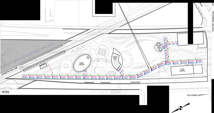
1. UTILITYCORRIDORS/SERVICECONNECTIONSANDAMENITIES/SERVICENEEDSAS SHOWNHEREINARENOTINTENDEDTOBECOMPREHENSIVENORPRESCRIPTIVE. UTILITYTYPES, SIZE/MATERIAL, LOCATIONS, ANDROUTINGTOBEADJUSTEDAS NEEDEDINLATERDESIGNPHASESPERFINALON-CAPPROGRAMMING.
2. PROPOSEDON-CAPUTILITIESTOBEROUTEDABOVETXDOTSTRUCTURALSLAB. REFERTOCONCEPTUALUTILITYCROSSSECTIONINREPORT.
3. CAPANDSTITCHPROJECTSHALLCOORDINATEWITHAUSTINWATERFOR POTENTIALRECLAIMEDWATERROUTINGINFUTUREDESIGNPHASE.
4. CAPDRAINAGETOBEROUTEDTOTXDOT-PROVIDEDDECKDRAINS&DRAINAGE SYSTEM.REFERTOCONCEPTUALDRAINAGEAXONSECTIONINREPORT.
Lead Consultant
Job Title
Drawing Title
CONCEPTUALUTILITYPLAN41STSTREETTOREDLINECAP
120'
Drawing Status
&
· AMENITYUTILITYSERVICENEEDS:
· CANOPY F/W/E
· WINDTURBINESE
· REDLINE E
· OPENSPACE W/E
· LIGHTING E
PROPOSEDON-CAP
UTILITYCORRIDOR:
-WATER(FIRE) -WATER(DOMESTIC) -ELECTRIC

NOTES:
1.UTILITYCORRIDORS/SERVICECONNECTIONSANDAMENITIES/SERVICENEEDSAS SHOWNHEREINARENOTINTENDEDTOBECOMPREHENSIVENORPRESCRIPTIVE. UTILITYTYPES,SIZE/MATERIAL,LOCATIONS,ANDROUTINGTOBEADJUSTEDAS NEEDEDINLATERDESIGNPHASESPERFINALON-CAPPROGRAMMING.
2.PROPOSEDON-CAPUTILITIESTOBEROUTEDABOVETXDOTSTRUCTURALSLAB. REFERTOCONCEPTUALUTILITYCROSSSECTIONINREPORT.
3.CAPANDSTITCHPROJECTSHALLCOORDINATEWITHAUSTINWATERFOR POTENTIALRECLAIMEDWATERROUTINGINFUTUREDESIGNPHASE.
4.CAPDRAINAGETOBEROUTEDTOTXDOT-PROVIDEDDECKDRAINS&DRAINAGE SYSTEM.REFERTOCONCEPTUALDRAINAGEAXONSECTIONINREPORT.
SubConsultant


WATER(FIRE) WATER(DOMESTIC) ELECTRIC TELECOM
WASTEWATER Legend


UTILITY CORRIDOR
CONCRETE VAULT WITH INTERMITTENT HATCH OPENINGS, TYP. STANDARD DUCT BANK BEYOND
WET UTILITIES SUPPORTED ON CONCRETE PEDESTAL IN LIGHTWEIGHT COARSE AGGREGATE, TYP.
UTILITY LINE TO AMENITY, TYP.
SPACEPROOFING FOR PURPLE PIPE AS REQUIRED. PURPLE PIPE SHALL BE 5'-0" CLEAR FROM WASTER WATER PIPE.
CHECKED & FINAL


© City of Austin
Figure 10: Changes in bending moment with restrictions on column loads: top (no restrictions), middle (no column zone), bottom (lower column load zone)
Figure 11: Loading Application: the vertical arrows represent the deck level area loads and tree weight above ground; the horizontal and curved arrows represent wind shear and moment
Figure 12: Pedestrian bridge programming example
Figure 13: Plan view (left) and section (right) of shade trees on TxDOT bridges
Figure 14:Shade tree zone configuration for reduced capacity caps
Appendices
1. Introduction
This report summarizes the final loading design criteria to be used in Texas Department of Transportation’s (TxDOT) design of the I-35 cap and stitch bridge deck structures.
The loading presented here is the heaviest loading envisioned by the City of Austin (COA) for the current and future programming planned on these caps. Designing the caps for this loading will enable flexibility for the COA to modify the programming as the design and construction of the caps progresses and for the duration of the 75+ design life of these structures. A scenario that illustrates this flexibility is that an area that is programmed to be a sports field in 2024 could be decided to be modified to be a 2-story building in 2045. Although the 2-story building is significantly heavier than the sports field, the cap has already been designed for the heavier 2-story building so no changes to the structure are required. If this flexibility was not provided, changes to the structure after it is built would be difficult and cost prohibitive.
Design responsibility for the cap structure sits with TxDOT and their consultants. The plans for the caps shall clearly articulate the loads that they are designed for so that future structural engineers responsible for the design of the buildings and other programming on the caps know the restrictions imposed upon their design. For the avoidance of confusion, only TxDOT’s PE stamped For Construction cap structure plans shall be used when determining what loads COA can apply to the caps when they are constructed.
2. Design Criteria
Conceptual load takedowns for the buildings have been performed in accordance with the requirements of Austin’s Building Technical Codes and include references to the principal design standards:
• International Building Code (IBC) 2021
• Minimum Design Loads for Buildings and Other Structures, ASCE 7-16
For areas without buildings the load takedowns have been performed in accordance with:
• AASHTO LRFD Bridge Design Specifications, 9th Edition
• AASHTO LRFD Guide Specifications for Design of Pedestrian Bridges, Second Edition
2.1 Loading Assumptions
2.1.1
Self Weight Dead Loads
Dead loads due to the self weight of structure, soil, or cladding elements are calculated from the following material densities:
• Reinforced normal weight concrete
• Structural steelwork
• Geofoam
• Pea gravel
• Glazed façade
• Masonry façade
• Saturated soil
• Tree root ball
2.1.2
Superimposed Dead Loads on Buildings
pcf
The table below lists the assumed floor finish and miscellaneous dead load allowances that are external to the self-weight of the structure of a building. Superimposed dead loads are based on the selected floor finishes, partitions, MEP services, landscaping, etc. The selection of these items will vary across future developments, but the following are based on standard finish types.
Table 1: Building superimposed dead load allowances
Program Space
Community Center, Retail, Gallery, Stage Assembly
Office & Residential
Roof - Unoccupied
Roof – Occupied
2.1.3 Live Loads
MEP services, ceiling, floor finish, hard flooring
Acceptable for thinset cement topping 25
MEP services, ceiling, Lightweight finish
Acceptable for carpet, epoxy, wood 15
MEP services, insulation, waterproofing, cover, and coating. Acceptable for asphalt shingles, gravel-surfaced, or lighter 15
MEP services, insulation, waterproofing, cover, coating, brick pavers, lightweight shade structure or solar panels above roof 35
The table below lists the assumed live load allowances. The live load allowances have been selected based on code requirements for different programming arrangements.
2: Building live load allowances
Exhibit, gallery, and collections programming includes spaces defined by densely filled rooms containing display casework or small tanks on shelving units. This 250 psf load is consistent with “heavy storage” typology defined in ASCE 7-16 and is often observed in museum collections spaces and tightly packed exhibits with casework or heavy display pieces. This loading type will not apply for lightly loaded art galleries containing paintings or small sculptures, which will only need to be designed for a 100 psf assembly loading.
Stage assembly programming occurs at well attended concerts and performance spaces and includes allowance for equipment rigging and temporary hung staging. It is assumed that this 150 psf load will occur within a singlestory light steel framed stage structure with longer 90ft roof spans.
Live load reduction has been applied for uniform floor and roof loads except for heavy live loads that exceed 100 psf per ASCE 7-16.
For areas without buildings, the live load allowances are provided below allowing for large gatherings of people, single heavy trucks (for example carrying soil or stage equipment), or ground level parking for passenger vehicles. The general (pedestrian) loading does not need to be considered concurrent with HL-93 design loading.
Table
Table 3: Areas without buildings live load allowances
Areas where HL-93 vehicles may access - See Figure 1
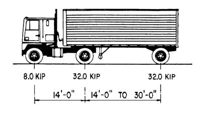

Design tandems consisting of a pair of 25 kip axles spaced 4 ft apart shall also be considered. Design lane load of 0.64 klf shall be considered to act concurrently with the design truck or tandem.
Emergency Vehicle (EV) loading shall be considered in the design of the cap structures per FHWA memo in reference to the FAST act dated November 3, 2016. This loading will account for a fully operational 82 kip quint (firetruck) to allow fire department access to the cap structures. The figure below demonstrates the axle loadings to be considered (EV2 & EV3).

AASHTO Pedestrian Bridges provides the below commentary and images of loading from pedestrians illustrating what the numbers in the tables above equate to. For reference, the ASCE building live loading is 100psf with a 1.6 load factor = 160psf total and the AASHTO pedestrian loading is 90psf with a 1.75 load factor = 157.5psf.
Figure 1: HL-93 Design truck per AASHTO LRFD BDS
Figure 2: EV Axle Diagram


There is a physical limit on how much load can be applied to a bridge from the static weight of pedestrians. It appears that this load is around 150 psf, based on work done by Nowak (2000) from where Figures C1 through C3 were taken. The use of a 90 psf nominal live load in combination with a load factor of 1.75 results in a loading of 158 psf, which provides a marginal, but sufficient, reserve compared with the maximum credible load of 150 psf.
2.1.4 Wind Loads
Wind load effects on the structure as a whole and on individual elements are considered with recognition of the variation of wind pressures over the height of the building and trees and orientation to the wind. Design wind pressures are calculated in accordance with ASCE7-16 based on the following parameters:
Table 4: Wind criteria
2.1.5 Other Loads
Snow and seismic loads on the buildings were determined to not govern the loads imposed on the cap structure over other gravity and lateral loads as per ASCE7-16 and are therefore not included herein.
2.1.6 Load Factors
All loads are provided unfactored.
2.2 Terminology
‘Longitudinal’ refers to a direction along the primary Tx70 girders and ‘Transverse’ is perpendicular.
2.3 Expansion Joint Locations
Expansion joints within the cap structures should only be placed longitudinally at abutment locations, and not at intermediate bents. Expansion joint spacing shall be maximized transversely across all caps. The images below display the desired configuration of expansion joints across the caps.


Figure 3: Example of Expansion Joint Locations in Cap Structures
3. Loading Recommendations
Appendix A contains an overall plan of the caps and stitches where the following zones are indicated:
• Typical Zones: The ‘buildings’ and ‘areas without buildings’ loadings provided below shall be applied at all ‘typical zone’ locations on the caps and stitches.
By designing to the most onerous building or non-building loading, the typical zones can have any mix of building and non-building amenities applied to them
• Special Zones: In some locations, TxDOT has indicated that the structure is unable to be designed to carry the typical loading based on restrictions on the available depth for structural elements. The loading on these special areas is prescribed in Section 4 of this report.
• Special Zones: In some locations, TxDOT has indicated that the structure is unable to be designed to carry the typical loading based on restrictions on the available depth for structural elements. The loading on these special areas is prescribed in Section 4 of this report.
• Trees on TxDOT Bridges: TxDOT’s bridges adjacent to the caps will form an integral part of the look and feel of the programming on the caps. The COA’s current cap programming envisions trees along the edges of the travelled way and loading has been provided below corresponding to the desired tree size and spacing.
• Trees on TxDOT Bridges: TxDOT’s bridges adjacent to the caps will form an integral part of the look and feel of the programming on the caps. The COA’s current cap programming envisions trees along the edges of the travelled way and loading has been provided below corresponding to the desired tree size and spacing.
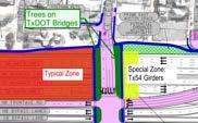

3.1 Buildings
The building loads were obtained assuming the following design basis:
3.1 Buildings
The building loads were obtained assuming the following design basis:
• Two stories of community center, retail, or assembly type loading with an occupied roof. The following additional typologies are acceptable as their required loads are less than that of the first:
• Two stories of community center, retail, or assembly type loading with an occupied roof. The following additional typologies are acceptable as their required loads are less than that of the first:
1-story park pavilion, office, community center, retail with occupied or green roof, residential, or museum storage
1-story park pavilion, office, community center, retail with occupied or green roof, residential, or museum storage
Long span stage: supports for this condition are assumed to exist in a 30’ x 90’ grid. The loads given herein are sufficient to resist this combination of area and point loading seen at the stage assembly condition.
Long span stage: supports for this condition are assumed to exist in a 30’ x 90’ grid. The loads given herein are sufficient to resist this combination of area and point loading seen at the stage assembly condition.
1-story EMS/ Fire Station which can park up to two (2) 82-kip quint EVs
1-story EMS/ Fire Station which can park up to two (2) 82-kip quint EVs
2-story mixed use, office, or residential
2-story mixed use, office, or residential
• A building with multiple levels of exhibit, gallery, and collections spaces will exceed the possible capacity of the I35 cap structures in many places and hence it has not been recommended as the design basis herein. Two stories of this type of programming can still be placed on the caps, however it would be in restricted locations that would need to be assessed on a case-by-case basis when the building design is completed.
• A building with multiple levels of exhibit, gallery, and collections spaces will exceed the possible capacity of the I35 cap structures in many places and hence it has not been recommended as the design basis herein. Two stories of this type of programming can still be placed on the caps, however it would be in restricted locations that would need to be assessed on a case-by-case basis when the building design is completed.
Figure 4: Different loading zones shown in Appendix A
Figure 4: Different loading zones shown in Appendix A
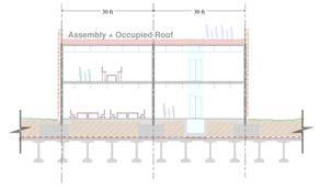
• The self-weight of the building structure is calculated based on a composite steel framed gravity system with steel moment frames at the superstructure and a slab on grade above geofoam at grade. Foundations will be located at column points with grade beams to locally spread the load. The weight of geofoam is calculated based on a 5.5 ft thickness which allows space for an adjacent 6 ft deep elevator pit. The following graphic summarizes the structure weight on each floor:
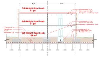
6:
• The superimposed dead load for each building floor includes the weight of finishes, MEP services, and an allowance for solar panels or shading at the roof. See the following graphic for the breakdown on each floor:
Figure 5: Proposed building section
Figure
Self-weight dead loads assumed for each floor

Figure 7: Superimposed dead load summarized for each building floor
• Assembly live loading is assumed at the ground level, first floor, and at an occupied roof:

8: Proposed building live loads at each floor
• The lateral system includes steel moment frames that are spread evenly throughout the building, avoiding large local shears or uplift forces at columns.
• The façade includes 4” of masonry cladding, or 36 psf area load at the exterior face of the building. Any façade system lighter than this is also an acceptable design.
• The total building height is 40 ft and assumes a 30 ft x 30 ft column grid; final column spacing of building structures will vary during design. This layout and corresponding loads imposed provide a realistic baseline of possible buildings for the design criteria of the I-35 cap structure.
3.1.1 Building Loading
The following loading shall be applied to the caps:
• 220psf dead load and 100psf live load applied at ground level with coexisting column point loads of 235kip dead load and 180kip live load at a 30’ x 30’ column spacing to be applied in any grid. Live load reduction is not permitted.
• Horizontal wind shear load of 20 kips at the base of column locations
Figure
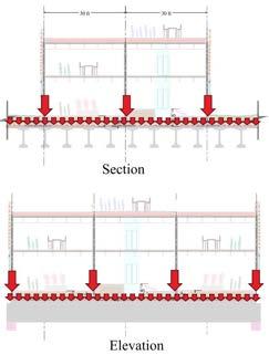
Figure 9: Loading Application: the small arrows represent the ground level area loads and the big arrows represent the column loads
Where the structure cannot be designed to take these loads the following shall be done:
• Girders shall be placed at minimum spacing with the maximum practical amount of strands and concrete strength used
• A ‘no-column’ zone of minimum possible length longitudinally shall be calculated
• A ‘lower column load’ zone of minimum possible length longitudinally shall be calculated
• The ground level loads shall remain unchanged
For example: a ‘no-column’ zone of 20’ is required at midspan of this section of cap OR a ‘lower-column load’ zone of 20’ with a reduction of 20% of loading is required at midspan of this section of cap. The below figure illustrates how the bending moments in the girders from the columns can be reduced by ~10% by imposing these constraints:

Figure 10: Changes in bending moment with restrictions on column loads: top (no restrictions), middle (no column zone), bottom (lower column load zone)
These restrictions on the allowable loading shall be agreed with COA
3.2 Areas Without Buildings
Loading in areas without buildings was obtained assuming the following design basis:
• Pedestrian assembly for events, HL-93 design loading, or EV loading
• Shade tree crown width of 35’ and height of 50’ (including 6’ trunk height) spaced 30’ on center with 4’ root ball depth and 11’-8” minimum root ball width (minimum of 700 cubic feet of soil volume per shade tree)
• 6” of pea gravel for drainage + waterproofing membrane
The loading above is the heaviest envisioned for the areas without buildings. Although it is not envisioned that 4’ of soil will be placed over the entire cap, there may be rows of shade trees aligned longitudinally with the girders where 4’ will be used. It should be noted that the loading this applies to the girders is of a similar magnitude to the building loads presented above.
Designing for the loading above will also allow for ground level parking of passenger vehicles, assembly of food trucks in a plaza, amenities like skateparks and playgrounds. The 4’ of soil required for shade trees is particularly heavy and these other types of programming would use geofoam to reduce the amount of soil required.
3.2.1
Areas Without Buildings Loading
The following loads shall be applied:
• 90 psf of pedestrian live load over the full area, HL-93 design loading, or EV loading. Live load reduction is not permitted.
• 500 psf of 4’ deep saturated soil over the full area
• 3.5 kip of tree weight above ground at tree locations
• 62.5 psf of drainage material over the full area
• 5 psf of waterproofing membrane over the full area
• 12.5 kips of shear and 400 kip-ft of moment from wind load per shade tree at the root ball resolved at deck level


11: Loading Application: the vertical arrows represent the deck level area loads and tree weight above ground; the horizontal and curved arrows represent wind shear and moment
3.3 Pedestrian Bridges
There is currently planned to be several locations where there are pedestrian bridges spanning onto the cap. The figure below illustrates an example of this type of programming.
Locations on cap structures that support pedestrian bridges do not impart greater loads onto the structure than the typical loading zones for buildings and non-buildings and therefore are covered under the existing design basis.
Figure
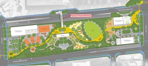
3.4 Trees on TxDOT Bridges
The programming envisioned on or adjacent to TxDOT bridges includes a mix of shade trees, ornamental trees, and valet/ drop off/ parking space. In the most onerous case, shade trees as described in Section 3.2 will be placed continuously across this region over an 8’ planter width. The figures below show the programming envisioned and a possible arrangement of planters:
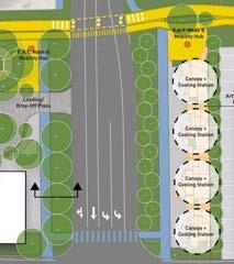

3.4.1 Trees on TxDOT Bridges Loading
The following loads shall be applied:
Figure 12: Pedestrian bridge programming example
Figure 13: Plan view (left) and section (right) of shade trees on TxDOT bridges
• 90 psf of pedestrian live load
• 500 psf of 4’ deep saturated soil
• 3.5 kip of tree weight above ground at tree locations
• 62.5 psf of drainage material
• 5 psf of waterproofing membrane
• 12.5 kips of shear and 400 kip-ft of moment from wind load per shade tree at the root ball resolved at deck level
The concept of trees on TxDOT bridges is still in discussion between CoA and TxDOT at the time of writing this report.
4. Special Zones
The loading recommendations as described in Section 3 of this report apply to all locations on the caps aside from locations designated as Special Zones which are highlighted in Appendix A and listed below:
• Special Zone 1: Cap adjacent to Holly Street with Tx54 girders
• Special Zone 2: Stitch adjacent to E Cesar Chavez Street with Tx54 girders
• Special Zone 3: Palm Park Tab
• Special Zone 4a: Caps adjacent to CapMetro Red Line with skewed girders and flare-out
• Special Zone 4b: Caps adjacent to CapMetro Red Line with restrictive spacing and skew
Each of these special zones will have unique loading and design recommendations which are documented herein.
4.1 Special Zone 1: Cap adjacent to Holly Street with Tx54 girders
Due to headroom clearance requirements at the cap adjacent to Holly Street, a smaller Tx54 girder is being designed by TxDOT. This reduces the capacity of this cap to take both building and non-building loads. The following sections describe the heaviest loads that this cap should be designed for.
4.1.1
Buildings
The building loads were obtained assuming the design basis as described in Section 3.1 of this report with a reduction equal to the anticipated reduction in cap capacity. The following typologies are acceptable considering the reduced capacity of the cap:
• 1-story park pavilion, office, community center, retail with occupied roof, residential, or long span stage
• 2-story mixed use, office, or residential (steel or wood framing only)
4.1.1.1
Building Loading
The following loading shall be applied to the caps:
• 220psf dead load and 100psf live load applied at ground level with coexisting column point loads of 150kip dead load and 100kip live load at a 30’ x 30’ column spacing to be applied in any grid. Live load reduction not permitted.
• Horizontal wind shear load of 20 kips at the base of column locations
• A net wind uplift of 20 kips at column locations
Loading application shall match that of Figure 9
4.1.2
Areas Without Buildings
Loading in areas without buildings was obtained assuming the following design basis:
• Pedestrian assembly for events, HL-93 design loading, or EV loading
• Ornamental tree crown width of 20’ and height of 20’ (including 3’ trunk height) spaced 15’ on center with 3’ root ball depth and 11’ minimum root ball width (minimum of 500 cubic feet of soil volume per ornamental tree)
• 6” thick Geofoam/ EPS Blocks
• 6” of pea gravel for drainage + waterproofing membrane
Designing for the loading above will also allow for ground level parking of passenger vehicles, assembly of food trucks in a plaza and amenities like skateparks and playgrounds. The 3’ of soil required for ornamental trees is particularly heavy and these other types of programming would use geofoam to reduce the amount of soil required.
The loading above is the heaviest continuous loading for the areas without buildings. Although it is not envisioned that 3’ of soil will be placed over the entire cap, there may be rows of ornamental trees aligned longitudinally with the girders where 3’ will be used.
Shade tree loading, like that described in Section 3.2, may be applied to this cap with the following restrictions:
• Shade trees must be placed 30’ on center
• Shade tree root ball length shall not exceed 15’
• Minimum fill (lawn or pavement) on geofoam must be placed between adjacent shade trees
It is expected that these requirements will keep the mixed shade tree/ fill loading on the Tx54 girders below or equal to that of the ornamental trees.
4.1.2.1
Areas Without Buildings Loading
For the ornamental tree areas, the following loads shall be applied:
• 90 psf of pedestrian live load over the full area, HL-93 design loading, or EV loading. Live load reduction is not permitted.
• 430 psf of 3’ deep saturated soil (includes 15% additional soil depth for future program where depth is less than 4’) over the ornamental tree areas
• 1.5 kip of tree weight above ground at tree locations
• 1 psf of 6” deep geofoam over the full area
• 62.5 psf of drainage material over the full area
• 5 psf of waterproofing membrane over the full area
• 3 kips of shear and 45 kip-ft of moment from wind load per ornamental tree at the root ball resolved at deck level
For the shade tree areas, the following loads shall be applied:
• 90 psf of pedestrian live load over the full area, HL-93 design loading, or EV loading. Live load reduction is not permitted.
• 500 psf of 4’ deep saturated soil over the “tree zone”
• 3.5 kip of tree weight above ground at tree locations
• 30 psf of supplementary dead load over the “lawn zone” to account for miscellaneous appurtenances such as lawn furniture, outdoor dining, and rock scrambles.
• 215 psf of 1.5’ deep saturated soil (includes 15% buffer for future program depth where depth is less than 4’) over the “lawn zone”
• 4 psf of 2’ deep geofoam over the “lawn zone”
• 62.5 psf of drainage material over the full area
• 5 psf of waterproofing membrane over the full area
• 12.5 kips of shear and 400 kip-ft of moment from wind load per shade tree at the root ball resolved at deck level
The figure below indicates the variation between tree and lawn zones as noted above.
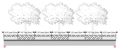
4.2 Special Zone 2: Stitch adjacent to E Cesar Chavez Street with Tx54 girders
The 50’ stitch south of E Cesar Chavez Street will be a continuation of the Tx54 bridge girders and therefore will have a reduced structural capacity. Refer to Section 4.1 of this report for loading criteria of this zone.
4.3 Special Zone 3: Palm Park Tab
Due to headroom clearance requirements at the Palm Park tab, smaller B20 box beams were proposed by TxDOT in their 30% design. This would reduce the capacity of this cap to take both building and non-building loads.
TxDOT confirmed on 8/8/2024 that additional capacity in this zone to accommodate loading as described in Section 3 of this report will be achieved through adjusting elevations around this portion of cap to utilize deeper Tx70 or Tx54 girders. Refer to Section 3 of this report for loading criteria of this zone.
4.4 Special Zone 4a: Caps adjacent to CapMetro Red Line with skewed girder and flare-out
A portion of the caps adjacent to CapMetro Red Line have a reduced capacity due to a skewed girder configuration with slightly longer maximum spans.
4.4.1 Buildings
The building loads were obtained assuming the design basis as described in Section 3.1 of this report.
4.4.1.1 Building Loading
Although girder capacity is reduced in this area, all building loads as described in Section 3.1.1 shall be applied to this special zone. The girders are anticipated to have enough capacity to resist these loads through utilization of a ‘no-column’ zone as illustrated in Figure 10
Figure 14:Shade tree zone configuration for reduced capacity caps
4.4.2 Areas Without Buildings
Loading in areas without buildings assumes the design basis as described in Section 3.2 of this report.
4.4.2.1 Areas Without Buildings Loading
All areas without building loads shall be applied to this special zone as described in Section 3.2.1
4.5 Special Zone 4b: Caps adjacent to CapMetro Red Line with restrictive spacing and skew
In the regions where capacity is severely limited by restrictive spacing, girder skew, and/ or headroom clearances, minimal programming shall be applied.
4.5.1 Buildings
Building loading shall not be applied in this region.
4.5.2 Areas Without Buildings
Loading in areas without buildings was obtained assuming the following design basis:
• Pedestrian assembly loading. Vehicular loading shall not be applied in this region. Vehicular access shall be restricted in these zones using a bollard system or equivalent.
• Concrete slab with stone pavers or soil for lawn space, 12” depth maximum build-up
• 2.5’ thick Geofoam/ EPS Blocks
• 6” of pea gravel for drainage + waterproofing membrane
4.5.2.1 Areas Without Buildings Loading
For the paved areas, the following loads shall be applied:
• 90 psf of pedestrian live load over the full area. Live load reduction is not permitted.
• 150 psf of 1’ deep paving over the full area
• 5 psf of 2.5’ deep geofoam over the full area
• 62.5 psf of drainage material over the full area
• 5 psf of waterproofing membrane over the full area
