
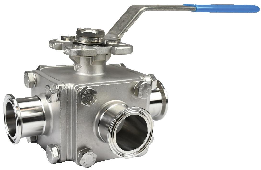
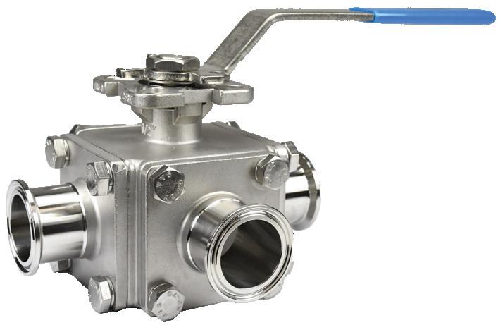
BV3S/4S-Series Sanitary Multi-Port Ball Valve
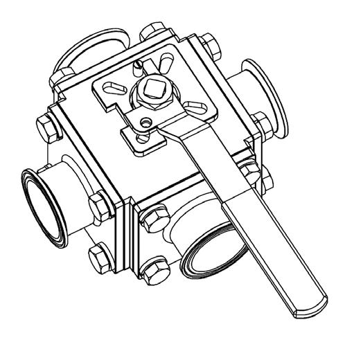
The BV3S/4S-series sanitary multi-port ball valve can be used for diversion or control of processing fluid. They are found in the food processing, beverage, winery, brewery, pet product, and industrial markets.
Sizes
• 1/2", 3/4", 1", 1-1/2", 2", 2-1/2", 3", 4"
Features
• Live-loaded stem packing
• Integral ISO 5211 mounting pad
• Lockable handle can prevent accidental actuation
• Standard internal entry blow-out proof stem design
• Precision stainless steel balls reduce torque and friction losses while extending shelf life
• Full port design on 1/2" through 3" and reduced port design on 4"
• Compact design for areas with tight space restrictions
• Fully encapsulated construction produces bubble tight seal
• Identification tagging available
• Balanced encapsulated construction minimizes cold flow
Materials
• Product contact metal components: CF8M
• Non-product contact metal components: 304 stainless steel
• Product contact seals: virgin PTFE, 15% reinforced PTFE, UHMW polyethylene, 50% stainless steel reinforced PTFE, 25% carbon reinforced PTFE
Specifications
• Standard connections: clamp
• Valve data
- Maximum pressure
- 1/2" to 2": 1000 PSI WOG
- 2-1/2" to 4": 800 PSI WOG
• Surface finish
- Product contact metal components: ≤ 32 Ra (lead-free brass)
- Non-product contact metal components: as cast or Ra ≤ 63
- Seat lubricant: BESSI F-100
- Stem lubricant: G.A. BESSIL 25
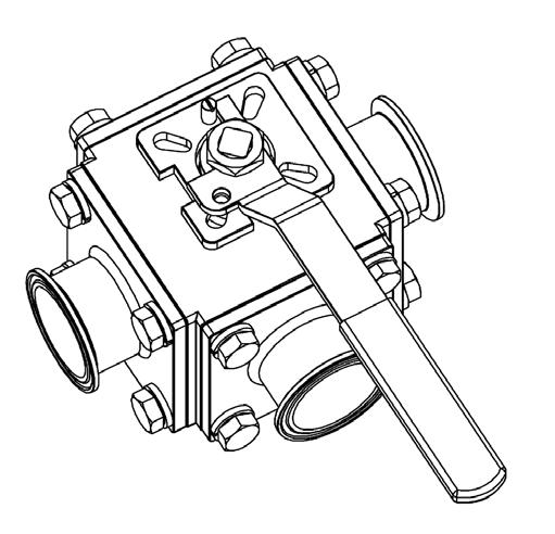
BV3S/4S-Series Sanitary Multi-Port Ball Valve - Dimensions
NOTE: Handle dimensions applicable for both 90° and 180° handles.
BV3S/4S-Series
BV3S/4S-Series Multi-Port Sanitary Ball Valve - Part Number Key
BV3S/4S-Series Multi-Port Sanitary Ball Valve Part Number Key
Example: BV3SVTF050C-A
Valve Style Code
3-way BV3S
4-way BV4S
Seat Material Code
Virgin PTFE V
15% glass reinforced PTFE G
25% carbon reinforced PTFE C
50% stainless steel reinforced PTFE S
Ultra high molecular weight polyethylene U
Ball Configuration Code
T Port T
L Port L Port
Full port F
Reduced port (4" only)1 R
BV3S V T F 050 C - A
Connections Code
Clamp (standard) C Weld B
Female I-Line F
Male I-Line M
Threaded Bevel T
Plain Bevel with Nut P
Q-Line Q
John Perry Plain with Nut J
John Perry Threaded H
Handle Code
90° manual handle (standard) A
180° manual handle B
Surface Finish Code
32 Ra I.D. blank
25 Ra I.D. -2
20 Ra I.D. -1
15 Ra I.D. -4
10 Ra I.D. -7
1Reduced port size is 3.15".
BV3S/4S-Series Actuated Ball Valve - Part Number Key
BV3/4S-Series Actuated Ball Valve Part Number Key
Example: 3CLV50CA100XX10
Valve Style Code
3-Way L-Port 3CL
3-Way T-Port 3CT
4-Way L-Port 4CL
4-Way T-Port 4CT
Seat Material Code
Virgin PTFE V
RTFE (15% glass reinforced PTFE) G
25% carbon reinforced PTFE C
50% stainless steel reinforced PTFE S
UHMW U
Size Code
1/2" 50 3/4" 75 1" 10 1-1/2" 15 2" 20 2-1/2" 25 3" 30 4" 40
Connections Code
Clamp C
Weld B
Female I-Line F
Male I-Line M
Threaded Bevel T
Plain Bevel with Nut P Q-Line Q
Female NPT 1
Flange K
Surface Finish Code
32 Ra A
25 Ra B
20 Ra C
15 Ra D
10 Ra E
32 Ra with K22 kolstering treatment F
Surface Finish 3CL V 50 C A
Continue number selection by following column 1 or 2 on page 5.
1.
BV3S/4S-Series Actuated Ball Valve - Part Number Key
(2)
magnetic reed SPDT, hermetically sealed, up to SIL3, Exia ready, cULus
cULus
mechanical
(2)
Pneumatic positioner 3-15 PSI input, 4-20mA
(2)
Electropneumatic positioner 4-20mA input, 4-20mA for feedback
Electropneumatic positioner 0-10v input, no feedback
Electropneumatic positioner 0-10v input, (2) SPDT mechanical
Electropneumatic positioner 0-10v input, 4-20mA for feedback
V200 rotary electropneumatic positioner 4-20mA input, 4-20mA feedback
Electropneumatic positioner 4-20mA input, no feedback, Class 1, Div II explosion proof
Single coil solenoid, 24VDC and 24V banjo solenoid valve with Form B plug
Single coil solenoid, 24VDC, AS-I, 2.5W low power
Single coil solenoid, 24VDC, intrinsically safe
Single coil solenoid, 24VDC, pre-wired to limit switch with CORDSET (dual keyway, 1/2"-20 UNF mating thread, single ended, straight female connector, 22 AWG PVC, auto color code 2P to 6P cable, 12’ length)
Single coil solenoid, 24VDC, explosion proof, Class H coil AW
Single coil solenoid, 24VAC AX
V200 rotary electropneumatic positioner 4-20mA input, 4-20mA feedback, Class 1, Div II explosion proof AY
Single coil solenoid, 24VDC, molded LED, ind. form, 2M leads AZ
TUFRAM COATED electropneumatic positioner 4-20mA input, no feedback BA
V200 rotary pneumatic positioner, (2) REED SWITCH feedback BB
Single coil solenoid, 120VAC, explosion proof, Class H coil BC
Single coil solenoid, 24VDC, pre-wired to limit switch, 6P male connection BD
Non-integral 304 stainless steel NEMA 4/4X 3 position control box, includes 3 manifold mount solenoids time delay relay and terminal strip (3 input control, does not require PLC) 24VDC BE
Non-integral 304 stainless steel NEMA 4/4X 3 position control box includes 3 manifold mount solenoids time delay relay and terminal strip (3 input control, does not require PLC) 120VAC BF
Flow Path
Rest A, energize B (spring return) 10
Rest A, energize D (spring return) 11
Energize A, energize B (double acting) 12
Energize A, energize D (double acting) 13
Rest B, energize A, engerize D (spring return, 180°) 14
Rest B, energize A (spring return) 15 BV3S/4S-Series Actuated Ball Valve - Part
Number Key
NOTE: Refer to the flow path codes on the following pages for other available configurations.
BV3S/4S-Series Ball Valve - Flow Path Position Codes
What is a multiport ball valve?
Multiport ball valves, also known as a 3-way and 4-way ball valves, provide an easy solution for applications requiring flow direction control in one valve body. 3-way or 4-way refers to the number of valve-to-application connection points there are.
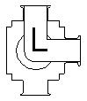
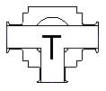
Dixon® Sanitary offers two variations to the 3-way and 4-way multiport ball valves, "L" and "T" port styles. "L" and "T" refer to the shape of the flow path inside the ball of the valve.
Why is a defined flow path necessary?
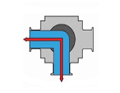
Rotating the ball inside the valve will yield different flow paths. The requirements of the application will determine the flow path needed when purchasing an actuated multiport ball valve.
When a multiport ball valve is ordered with a manual handle, adjusting the flow path for the application may be as simple as rotating the valve by hand. However, when a multiport ball valve is actuated, the flow path information is required to ensure the valve and necessary components are built in the proper position to meet the application requirements.
BV3S/4S-Series Actuated Ball Valve - Flow Path Position Codes
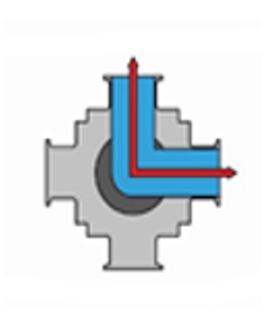
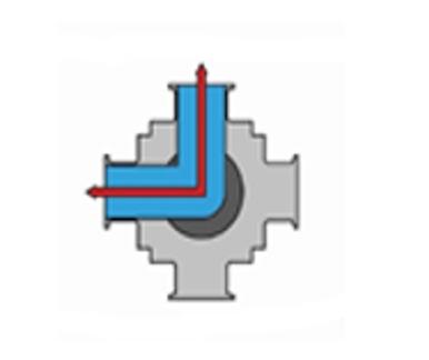
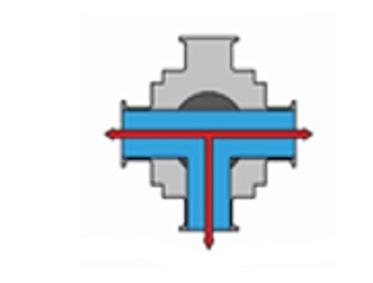
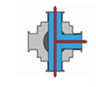
Understanding the flow path diagrams
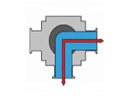
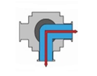
When viewing Dixon Sanitary's flow path code tables, it is important to understand what the diagrams mean. The flow path diagrams are drawn as if the top half of the valve was cut off and you are looking straight down on the cut valve. This view shows the L or T shape inside the ball, the position of the ball, and how many connection points are on the valve. Each position is given a letter designation A, B, C, or D.


Example: This diagram shows a 3-way (3 connection points), L-port ball valve ("L" shaped path inside the ball), currently in position "A" (position designation assigned by Dixon Sanitary).
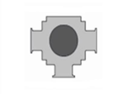
Example: This diagram shows a 3-way (3 connection points), L-port ball valve ("L" shaped path inside the ball), currently in position "C" (position designation assigned by Dixon Sanitary). This position is essentially a shut-off position for the L-port valve. This position is not possible on a T-port valve.
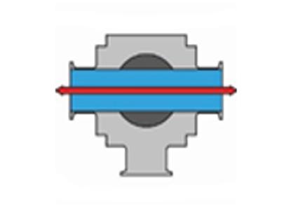
Example: This diagram shows a 4-way (4 connection points), T-port ball valve ("T" shaped path inside the ball), currently in position "A" (position designation assigned by Dixon Sanitary.
Steps to determine the flow path
1. Determine the core function of the valve
- Will this valve be used to shut off and divert flow? Change the destination of flow? Mix two sources of flow into one?
2. Determine how many flow positions the valve will need to operate. E.g. diverting between two destinations and a shut off position would be three positions.
3. Determine actuator function
- First determine the source of power for the actuator. Will this be pneumatically or electrically powered? If pneumatic, does it need to be spring return or double acting? Spring return means if air power is lost, the actuator will rotate the valve back to a predetermined "fail" or "rest" position. Double acting and electric both rotate only when air power or electric power are applied.
4. Select the flow path code from the list of available combinations.
BV3S/4S-Series Ball Valve - Flow Path Position Codes
3-Way L-Port
3-Way T-Port
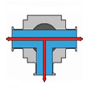
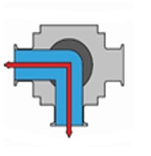
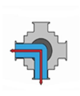
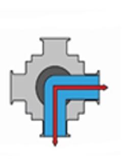
4-Way L-Port 4-Way T-Port
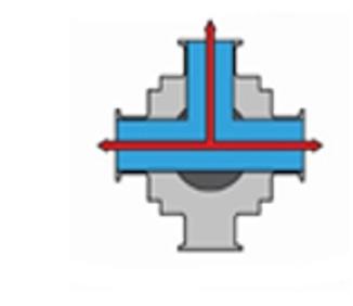
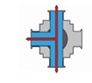
BV3S/4S-Series Ball Valve - Flow Path Position Codes
2 Position
3-Way | L-Port | Spring Return
Rest Position

Energize Position
3-Way | L-Port | Double Acting or Electric
Energize Position
Energize Position

BV3S/4S-Series
3-Way | T-Port | Spring Return
Ball Valve - Flow Path Position Codes
Energize Position


BV3S/4S-Series Ball Valve - Flow Path Position Codes
3-Way | T-Port | Double Acting or Electric
Energize Position
Energize Position
4-Way | L-Port | Spring Return
Code
Air Rotation Detection
Rest Position


4-Way | L-Port | Double Acting or Electric
Code
Energize Position

Energize Position
Energize Position
BV3S/4S-Series
BV3S/4S-Series Ball Valve - Flow Path Position Codes
4-Way | T-Port | Spring Return


4-Way | T-Port | Double Acting or Electric
Energize
Energize Position
BV3S/4S-Series Ball Valve - Flow Path Position Codes BV3S/4S-Series
3 Position
3-Way | L-Port | Spring Return
Code 26 28 29
Rotation 180° 180° 180°
Air Rotation Detection Either Either Either
Return Either Either End
3-Way | L-Port | Double Acting or Electric
Code 30
Rotation 180° A
Energize Position
Rest Position
Energize Position
Energize Position
Energize Position
Energize Position
BV3S/4S-Series Ball Valve - Flow Path Position Codes BV3S/4S-Series
3-Way | T-Port | Spring Return
Energize Position
Energize Position
NOTE: 3-way, T-Port, Spring Return continued on the next page
BV3S/4S-Series
BV3S/4S-Series Ball Valve - Flow Path Position Codes
3-Way | T-Port | Spring Return
Rest Position
Energize Position
Energize Position
BV3S/4S-Series
BV3S/4S-Series Ball Valve - Flow Path Position Codes
3-Way | T-Port | Double Acting or Electric
Energize Position
Energize Position
Energize Position
BV3S/4S-Series
BV3S/4S-Series Ball Valve - Flow Path Position Codes
4-Way | L-Port | Spring Return
Rest Position

Energize Position

Energize Position
NOTE: 4-way, L-Port, Spring Return continued on the next page
BV3S/4S-Series
BV3S/4S-Series Ball Valve - Flow Path Position Codes
4-Way | L-Port | Spring Return
Energize Position
Energize Position
BV3S/4S-Series
BV3S/4S-Series Ball Valve - Flow Path Position Codes
4-Way | L-Port | Double Acting or Electric
Energize Position
Energize Position
Energize Position
BV3S/4S-Series
BV3S/4S-Series Ball Valve - Flow Path Position Codes
4-Way | T-Port | Spring Return
Energize Position
Energize Position
NOTE: 4-way, T-Port, Spring Return continued on the next page
BV3S/4S-Series
BV3S/4S-Series Ball Valve - Flow Path Position Codes
4-Way | T-Port | Spring Return
Energize Position
Energize Position
BV3S/4S-Series
BV3S/4S-Series Ball Valve - Flow Path Position Codes
4-Way | T-Port | Double Acting or Electric
Energize Position
Energize Position
Energize Position
BV3S/4S-Series Actuated Ball Valve - Break Torque
BV3S/4S-Series Actuated Ball Valve - Seat Multiplier
BV3S & BV4S SERIES
NOTE: 1) Base Break Torque * Material Torque Multiplier = Material Break Torque
PRESSURE TEMPERATURE CHARTS
BV3S/4S-Series Ball Valve - Pressure Temperature Charts
) G I S P ( e r u s s e r P
BV3S/4S-Series Ball Valve - Pressure Temperature Charts
BV3S/4S-Series Ball Valve - Bill of Materials (1/2" to 1")
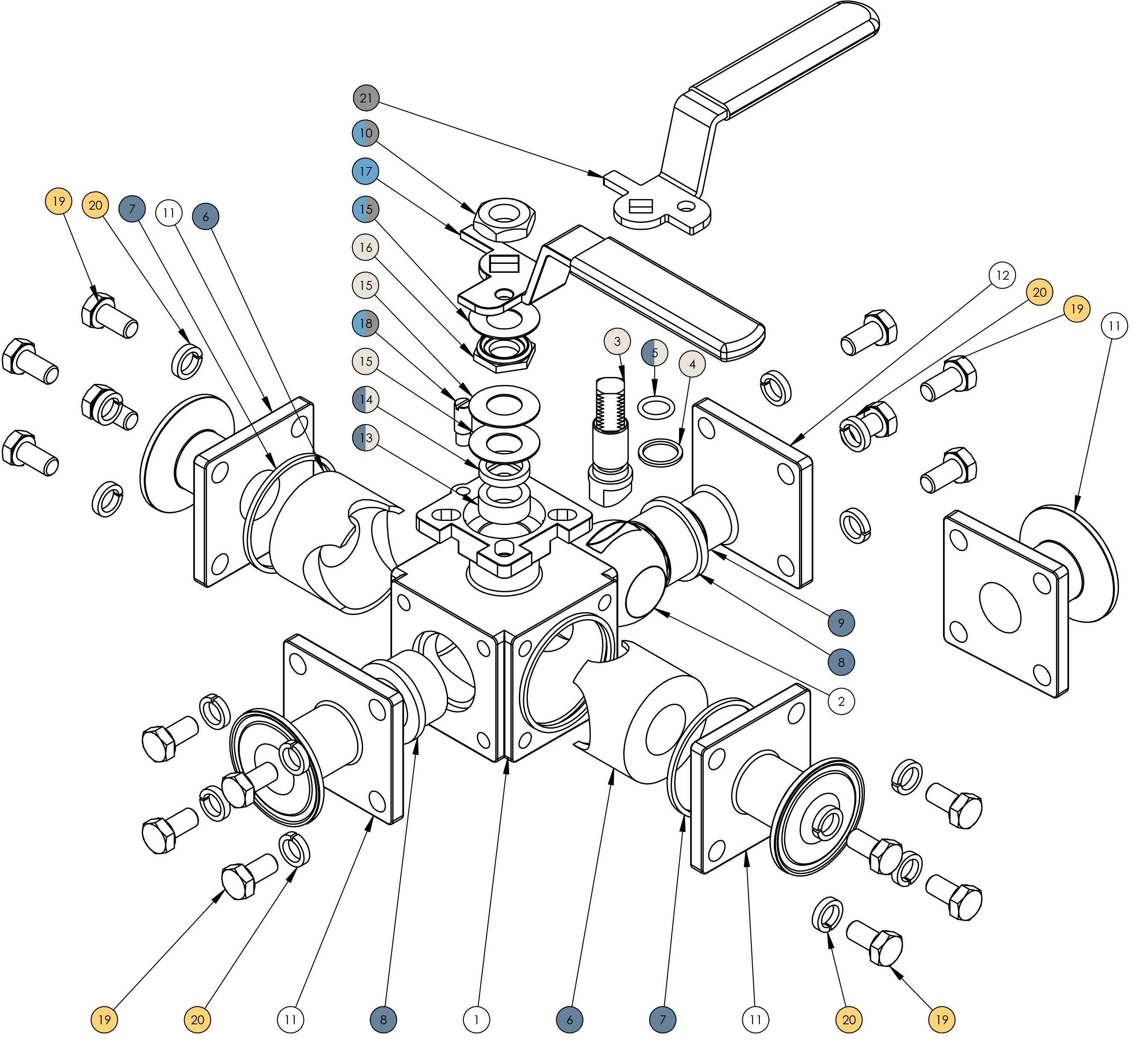
Included in seat kit (page 34)
Included in handle kit (page 34)
Included in 180° handle kit (page 34)
Included in stem kit (page 34)
Included in bolt and nut kit (page 34) (3-way only)
BV3S/4S-Series Ball Valves - Bill of Materials (1/2" to 1")
BV-3SVFTB075 T-port ball
1Top bevel washer is included in handle kit(s) and bottom
BV3S/4S-Series Ball Valves - Bill of Materials (1-1/2")
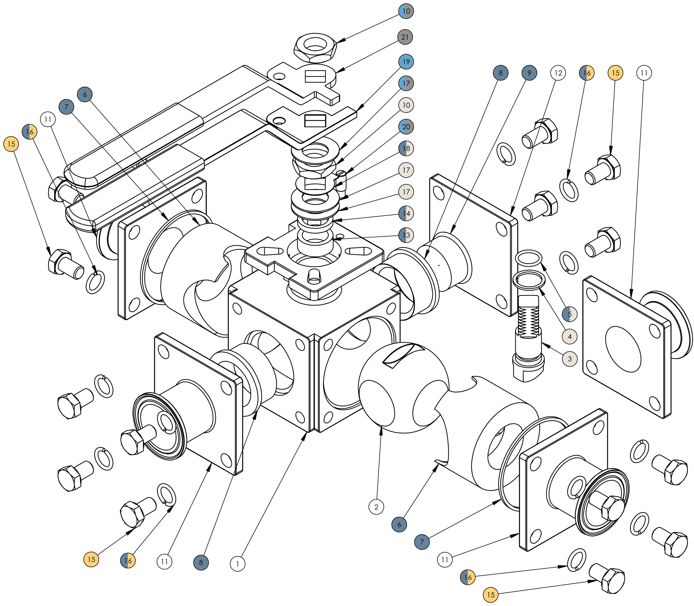
Included in seat kit (page 34)
Included in handle kit (page 34)
Included in 180° handle kit (page 34)
Included in stem kit (page 34)
Included in bolt and nut kit (page 34) (3-way only)
BV3S/4S-Series Ball Valves - Bill of Materials (1-1/2")
1Top stem nut is included in the handle kit(s) and bottom stem nut is included in the stem kit.
2Top bevel washer is included in the handle kit(s) and bottom two bevel washers are included in the stem kit.
BV3S/4S-Series Ball Valves - Bill of Materials (2")
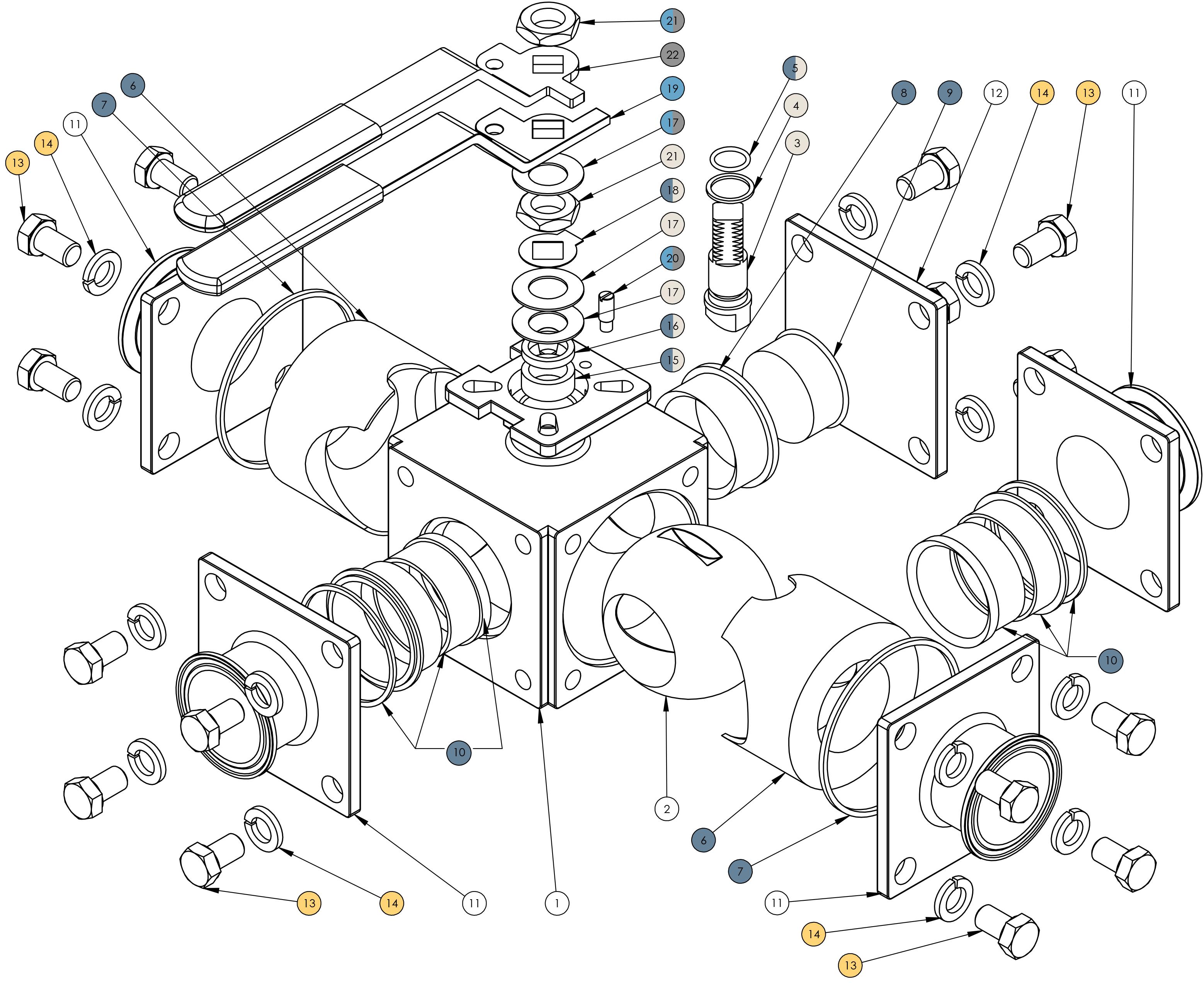
Included in seat kit (page 34)
Included in handle kit (page 34)
Included in 180° handle kit (page 34)
Included in stem kit (page 34)
Included in bolt and nut kit (page 34) (3-way only)
BV3S/4S-Series Ball Valve - Bill of Materials (2")
1Top bevel washer is included in the handle kit(s) and bottom two bevel washers are included in the stem kit.
2Top stem nut is included in the handle kit(s) and bottom stem nut is included in the stem kit.
BV3S/4S-Series Ball Valve - Bill of Materials (2-1/2" to 4")
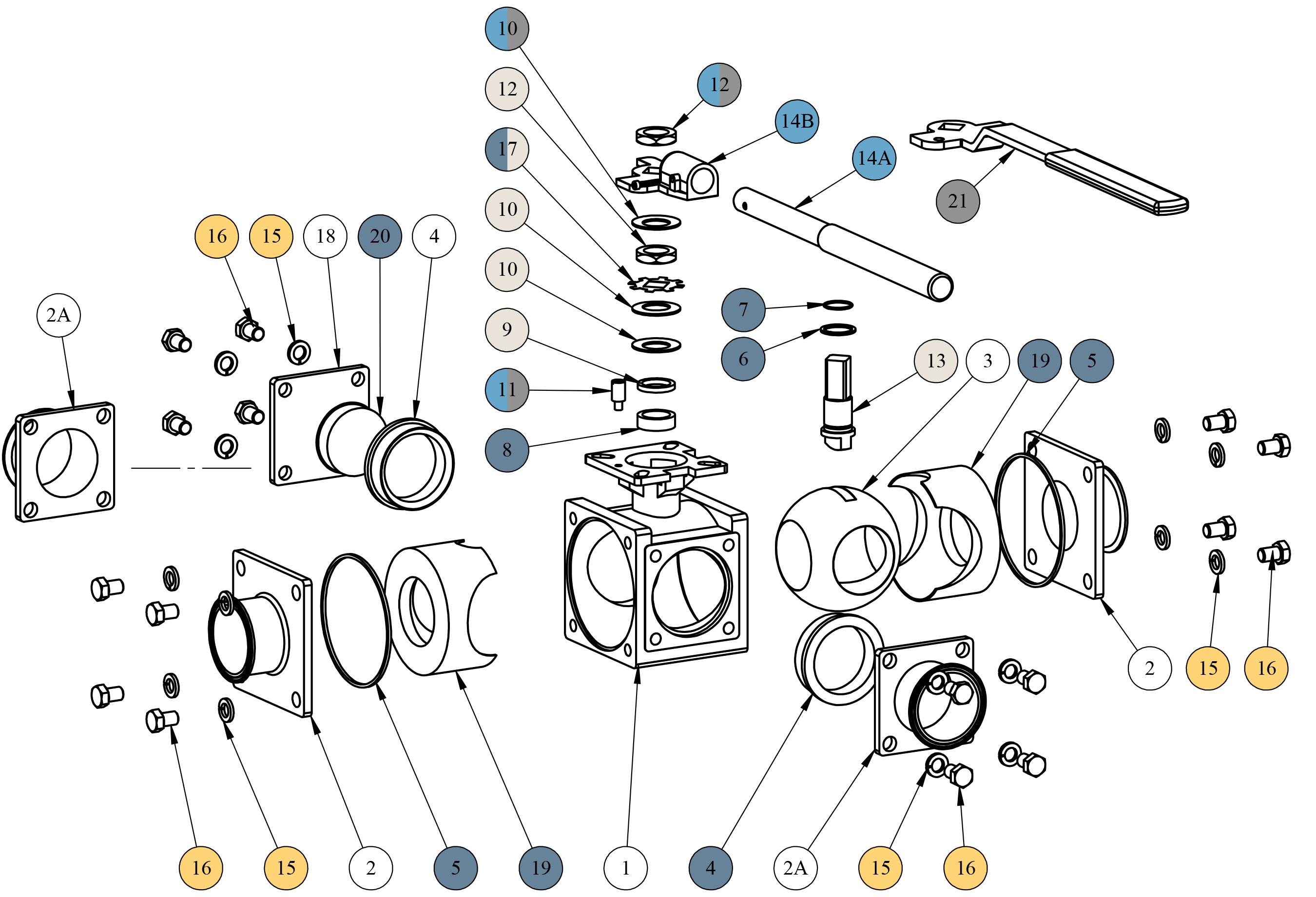
Included in seat kit (page 34)
Included in handle kit (page 34)
Included in 180° handle kit (page 34)
Included in stem kit (page 34)
Included in bolt and nut kit (page 34) (3-way only)
BV3S/4S-Series Ball Valve - Bill of Materials (2-1/2" to 4")
1Top bevel washer is included in the handle kit(s) and bottom two bevel washers are included in the
2Top stem nut is included in the handle kit(s) and bottom stem nut is included in the
Size
1/2"
3/4"
1"
1-1/2"
2"*
2-1/2"
3"
4"
BV3S-Series Ball Valve - Repair Kit Part Numbers
Seat Kits
BV-3SVFRK050
BV-3SVFRK075
BV-3SVFRK100
BV-3SVFRK150
BV-3SVFRK200
BV-3SVFRK250
BV-3SVFRK300
BV-3SVRRK400
BV-3SGRK050
BV-3SGRK075
BV-3SGRK100
BV-3SGRK150
BV-3SGRK200
BV-3SGRK250
BV-3SGRK300
BV-3SGRK400
BV-3SCRK050
BV-3SCRK075
BV-3SCRK100
BV-3SCRK150
BV-3SCRK200
BV-3SCRK250
BV-3SCRK300
BV-3SCRK400
BV-3SSRK050
BV-3SSRK075
BV-3SSRK100
BV-3SSRK150
BV-3SSRK200
BV-3SSRK250
BV-3SSRK300
BV-3SSRK400
*The 3-piece small assembly (2" only) contains (2) seat material components and (1) 316L stainless steel ring.
Handle Kits
Size
1/2"
3/4"
1"
1-1/2"
2"
2-1/2"
3"
4"
90° Part #
BV-23-HA050-075
BV-23-HA100
BV-23-HA150-200
BV-23-HA-17
BV-23-HA-22
Stem Kits
1/2"
3/4"
1"
1-1/2"
2"
2-1/2"
3"
4"
Size
1/2"
3/4"
1"
1-1/2"
2"
2-1/2"
3"
4"
BV3SV-SML-050
BV3SV-SML-075
BV3SV-SML-100
BV3SV-SML-150
BV3SV-SML-200
BV3SV-SML-250
BV3SV-SML-300
BV3SV-SML-400
Bolt and Washer Kit (3-way only)
Part #
BV-3X-BN050
BV-3X-BN075
BV-3X-BN100
BV-3X-BN150
BV-3X-BN200
BV-3X-BN250
BV-3X-BN300
BV-3X-BN400
BV-3SURK050
BV-3SURK075
BV-3SURK100
BV-3SURK150
BV-3SURK200
BV-3SURK250
BV-3SURK300
BV-3SURK400
180° Part #
BV-3-HA18-9
BV-3-HA18-11
BV-3-HA18-14
BV-3-HA18-17
BV-3-HA18-22
BV3SV-SMT-050
BV3SV-SMT-075
BV3SV-SMT-100
BV3SV-SMT-150
BV3SV-SMT-200
BV3SV-SMT-250
BV3SV-SMT-300
BV3SV-SMT-400