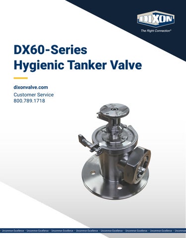
DX60-Series Hygienic Tanker Valve dixonvalve.com Customer Service 800.789.1718
DX60 | IOM
dixonvalve.com • 800.789.1718
1
Table of Contents Table of Contents............................................................................................................................................................................................ 2 Safety............................................................................................................................................................................................................ 3-4 General Guidelines...................................................................................................................................................................................... 3 Owner Must Ensure..................................................................................................................................................................................... 4 Care of Stainless Steel.................................................................................................................................................................................... 5 Technical Specifications................................................................................................................................................................................. 6 Installation and Start-Up................................................................................................................................................................................. 7 Unpacking.................................................................................................................................................................................................... 7 Tools Needed.............................................................................................................................................................................................. 7 Function Testing.......................................................................................................................................................................................... 7 Installation Orientation............................................................................................................................................................................... 8 Cleaning....................................................................................................................................................................................................... 9 General Maintenance...................................................................................................................................................................................... 9 Maintenance and Servicing Intervals......................................................................................................................................................... 9 Lubrication................................................................................................................................................................................................... 9 Inspection.................................................................................................................................................................................................. 10 Manual Cleaning (COP)............................................................................................................................................................................ 10 Cleaning in Place (CIP)............................................................................................................................................................................. 10 Assembly and Disassembly....................................................................................................................................................................12-15 Assembly..............................................................................................................................................................................................12-15 Disassembly.............................................................................................................................................................................................. 15 Repair Kits..................................................................................................................................................................................................... 16 Bill of Materials........................................................................................................................................................................................17-19 Individual Components........................................................................................................................................................................20-22 Dimensions...............................................................................................................................................................................................23-26 Part Number Key........................................................................................................................................................................................... 27 Troubleshooting............................................................................................................................................................................................ 28 Limited Warranty........................................................................................................................................................................................... 29
2
dixonvalve.com • 800.789.1718
DX60 | IOM
Safety The following signs may be used in this manual. To avoid serious injury and/or possible damage to equipment, pay attention to these messages. Hazards or unsafe practices could result in severe personal injury or death.
Indicates a hazardous situation that, if not avoided, will result in death or serious injury.
Indicates a hazardous situation that, if not avoided, could result in death or serious injury.
Indicates a hazardous situation that, if not avoided, could result in minor or moderate injury. May also be used to alert against an unsafe operating or maintenance practice.
Use only replacement parts and devices recommended by the manufacturer to maintain the integrity of the equipment. Make sure the parts are properly matched to the series, model, serial number, and revision level of the equipment. Safety labels are placed on equipment where appropriate. Do not remove any labeling from any piece of equipment. Replace any label that is missing. DO NOT modify any Dixon® product. Non-factory modifications could create hazardous conditions and void all warranties. DO NOT attempt to use a Dixon product in any application that exceeds the product rating.
General Guidelines • The owner must comply with these operating instructions and the authorized use of this piece of equipment. Should problems arise that cannot be solved using these operating instructions, please contact Dixon Sanitary. We will be happy to provide further assistance. • If any modification work is performed on the product by the owner, Dixon shall no longer be considered the manufacturer of the device. In such cases, all components must be subjected to a new certification process for any applicable certifications that the equipment holds. Unless agreed to in writing by Dixon, liability, warranties, and guarantees shall immediately be deemed null and void as soon as you: - Perform modifications/conversion work on the product. - Use the product for unauthorized purposes. - Remove or disable safety elements. - Process products whose material, form, and size do not correspond exactly to the description provided. - Make alterations to the original state of the device. • The operating instructions are regarded as part of the valve. • The operating instructions shall be valid for the entirety of the device's lifespan. • The operating and maintenance personnel must always be able to access the operating instructions. • The safety instructions provided in the operating instructions must be observed. • The operating instructions must be maintained and updated as necessary. • The operating instructions must be passed on to any subsequent owners or operators of the device.
DX60 | IOM
dixonvalve.com • 800.789.1718
3
Safety Owner Must Ensure... • The product is used only as authorized. • The product is used only when it is in fault-free, fully functional condition and the safety equipment is regularly checked to ensure that it is fully functional. • The product is operated, maintained, and repaired only by personnel with the appropriate qualifications and authorization. • Checks are made before the product is put into operation to ensure that only the authorized person is in the work area and no one is in danger of being injured if the product is in operation. • The product is checked for visual damage prior to commissioning to ensure that it is operated only when free of faults. • Any defects are reported immediately to the appropriate supervisor. • All safety and warning notices attached to the equipment are legible, and none are removed. • The operating instructions are always kept close to the product operation site, in a legible and complete state. • Personnel are regularly instructed on all occupational safety and environmental protection issues and are familiar with and observe the operating instructions, especially the safety instructions contained herein. • Personnel are trained and supervised to ensure that they follow safety measures, including the obligatory use of personal protective equipment. • The product is only connected to pipelines that are depressurized at the time of connection. • There is no tensile or compressive stress acting on the product connections. • There is no residual risk at any point where pressure could occur. Pressure can cause sudden failure in or damage to the lines and connections. • Warning notices in the documentation for supplier modules are observed and integrated into the risk assessments in the workplace.
4
dixonvalve.com • 800.789.1718
DX60 | IOM
Care of Stainless Steel The stainless steel components in Dixon® Sanitary equipment are machined, welded, and assembled by skilled craftsmen using manufacturing methods that preserve the corrosion-resistant quality of the stainless steel. Retention of corrosion-resistant qualities under processing conditions requires regular attention to the precautions listed below. Examples of corrosion that can result from improper care are included below. • Regularly check all electrical devices connected to the equipment for stray currents caused by improper grounding, damaged insulation, or other defects. Corrosion: Pitting often occurs when stray currents encounter moist stainless steel. • Never leave rubber mats, fittings, wrenches, or other tools in contact with stainless steel. Corrosion: pitting or galvanic action. Objects retard complete drying, preventing air from reforming the protective oxide film. Galvanic corrosion occurs when two dissimilar metals touch when wet. • Immediately rinse equipment after use with warm water until the rinse water is clear. Clean the equipment (COP or CIP) as soon as possible after rinsing. Corrosion: discoloration, deposits, and pitting. Product deposits often cause pitting beneath the particles. • Use only recommended cleaning compounds. Purchase chemicals from reputable and responsible chemical manufacturers familiar with stainless steel processing equipment. Ensure they continuously check the effects of their products on stainless steel. • Use cleaning chemicals exactly as specified by the manufacturer. Do not use excessive concentrations, temperatures, or exposure times. Corrosion: pitting, discoloration, or stress cracks. Permanent damage often occurs from excessive chemical concentrations, temperatures, or exposure times. • For manual cleaning, use only soft non-metallic brushes, sponges, or pads. Brush with the grain on polished surfaces to avoid scratching the surface. Corrosion: pitting, scratches. Metal brushes or sponges will scratch the surface and promote corrosion over a period of time. Metal particles allowed to remain on a stainless steel surface will cause pitting. • Use chemical bactericides exactly as prescribed by the chemical manufacturer in concurrence with the local health authority. Use the lowest permissible concentration, temperature, and exposure time possible. Flush immediately after bacterial treatment. In no case should the solution be in contact with stainless steel for more than 20 minutes. Corrosion: protective film destroyed. Chlorine and other halogen bactericides can destroy the protective film. A few degrees increase in temperature greatly increases chemical activity and accelerates corrosion. • Regularly inspect the joints in pipelines. Be sure all connections are tight fitting without binding. Corrosion: crevice corrosion. Small crevices caused by improperly seated gaskets will promote crevice corrosion. Stainless steel under stress will develop stress cracking, especially in the presence of bactericides containing chlorine. • Regularly inspect equipment for surface corrosion (i.e. pitting deposits, stress cracks, etc.). If deposit or color corrosion is detected, remove it immediately using mild scouring powder and detergents. Rinse thoroughly and allow to air dry. Review production and cleaning procedures to determine the cause. NOTE: If corrosion is not removed, the protective film cannot be restored, and corrosion will continue at an accelerated rate.
DX60 | IOM
dixonvalve.com • 800.789.1718
5
Technical Specifications Materials of Construction • Product contact metal components: AISI 304 (1.4301) • Non-product contact components: refer to BOM for individual component material • Product contact elastomers: FKM / nitrile rubber (FDA 21CFR177.2600 and 3A Class I) Holding Pressure Technical Data • Maximum product pressure: 75 PSI (5.17 bar) Product Temperature Technical Data • Maximum operating temperature: 212°F (100°C) – for higher temperatures, consult factory • Minimum operating temperature: -20°F (-28.9C) – for higher temperatures, consult factory Surface Finish Technical Data • Product contact components: Ra ≤ 32 • Optional finishes: upon request • Non-product contact components: Ra ≤ 63 Size and Connections • 3" x 3" with 4-bolt flange-to-trailer x male threaded bevel seat • 6" x 3" with 6" triclamp flange-to-trailer x male threaded bevel seat • Other options and combinations available upon request Cleaning Method • 3A certified for clean-in-place (CIP) or clean-out-of-place (COP): 3A standard 53-07
Product Weight Chart Valve Part # DX603010A1GB1R DX603010A1GV1R DX603010A1GB1 DX603010A1GV1 DX603010A1GB3R DX603010A1GV3R DX603010A1GB3 DX603010A1GV3 DX603010A1GV2R DX603010A2GB2R DX603010A1GB2 DX603010A1GV2 DX6063N10A1GV2 DX6063N10A1GB2 DX606010A3GV2 DX606010A3GV2X 6
Description 3" x 3" with 4-bolt flange-to-trailer x male threaded bevel seat, nitrile rubber seals, freeze rod plunger, aluminum dust cover (lanyard style, no post) 3" x 3" with 4-bolt flange-to-trailer x male threaded bevel seat, FKM seals, freeze rod plunger, aluminum dust cover (lanyard style, no post) 3" x 3" with 4-bolt flange-to-trailer x male threaded bevel seat, nitrile rubber seals, standard plunger, aluminum dust cover (lanyard style, no post) 3" x 3" with 4-bolt flange-to-trailer x male threaded bevel seat, FKM seals, standard plunger, aluminum dust cover (lanyard style, no post) 3" x 3" with 4-bolt flange-to-trailer x male threaded bevel seat, nitrile rubber seals, freeze rod plunger, aluminum dust cover (5/8" UNC threaded post and nut) 3" x 3" with 4-bolt flange-to-trailer x male threaded bevel seat, FKM seals, freeze rod plunger, aluminum dust cover (5/8" UNC threaded post and nut) 3" x 3" with 4-bolt flange-to-trailer x male threaded bevel seat, nitrile rubber seals, standard plunger, aluminum dust cover (5/8" UNC threaded post and nut) 3" x 3" with 4-bolt flange-to-trailer x male threaded bevel seat, FKM seals, standard plunger, aluminum dust cover (5/8" UNC threaded post and nut) 3" x 3" with 4-bolt flange-to-trailer x male threaded bevel seat, FKM seals, freeze rod plunger, no dust cover (for cabinet installation) 3" x 3" with 4-bolt flange-to-trailer x male threaded bevel seat, nitrile rubber seals, freeze rod plunger, no dust cover (for cabinet installation) 3" x 3 with 4-bolt flange-to-trailer x male threaded bevel seat, nitrile rubber seals, standard plunger, no dust cover (for cabinet installation) 3" x 3" with 4-bolt flange-to-trailer x male threaded bevel seat, FKM seals, standard plunger, no dust cover (for cabinet installation) 6" x 3" with 6" triclamp-to-trailer x male threaded bevel seat, FKM seals, standard plunger, no dust cover (for cabinet installation) 6" x 3" with 6" triclamp-to-trailer x male threaded bevel seat, nitrile rubber seals, standard plunger, no dust cover (for cabinet installation) 6" x 6" with triclamp-to-trailer x 90° 6" triclamp, FKM seals, standard plunger (for cabinet installation) 6" x 6" with 6" triclamp-to-trailer x 90° 6" triclamp, FKM seals, standard plunger, body clamp with hex nut (for cabinet installation dixonvalve.com • 800.789.1718
Weight 28.0 lbs 28.0 lbs 27.0 lbs 27.0 lbs 30.5 lbs 30.5 lbs 29.4 lbs 29.4 lbs 26.4 lbs 26.4 lbs 25.4 lbs 25.4 lbs 25.4 lbs 19.9 lbs 30.0 lbs 30.0 lbs DX60 | IOM
Installation and Start-Up The following should be performed upon receiving the product and prior to installation and use of product. It is important that all the following processes and procedures are carefully followed and adhered to. Dixon® is not responsible for any damage that occurs during the unpacking or installation process.
Unpacking Carefully unpack the valve and inspect each part for any damage that may have occurred during shipment. The valve may be shipped with aluminum dust cover attached (depending on the model ordered), so be sure to inspect the cover for any signs of damage as well as the valve itself. Report any damages to the carrier immediately. The valve is shipped with all necessary certificates, manuals, and operational stickers. Please add this paperwork to the plant maintenance files for future use and reference. All operational stickers should be placed on the trailer near the valve. Additional information for the valve can be found at dixonvalve.com.
Tools Needed The following tools will be required for any maintenance on the product: • 5/16" allen key wrench • 7/16" box wrench • O-ring pick tool • Grease type (under lubrication section) • Thread locker
Function Testing Scan QR code below for operational video
Valves Purchased Prior to 2024
Latest Revision
• Check visually to ensure that equipment is not leaking • Any defective seal that could have been damaged during disassembly or assembly must be replaced • Check all equipment components for any signs of damage and replace damaged components • Ensure that all clamps and fasteners are secure • Confirm all pipes and fittings connected to the equipment permitted for use are in the intended pressure range • Check that the maximum pressure indicated on the equipment or in the specification section of this manual have been complied with
DX60 | IOM
dixonvalve.com • 800.789.1718
7
Installation Orientation Equipment must be installed in the proper orientation to ensure proper functionality and cleanability. Please refer to the following diagrams below for proper installation.
GROUND IMPORTANT: The valve must be installed with the outlet facing downward if the valve is going to be cleaned-in-place (CIP'd). If the valve is installed with the outlet port in any other orientation other than what is depicted above, after the CIP cycle, the valve body clamp and the plunger-bonnet assembly must be removed to allow complete draining before reinstalling.
Operation and Safety Labels English Sticker
Spanish Sticker
Instructions For Valve Operation
Instrucciones Para El OperaciÓn De La Válvula Para abrir la válvula
To Open Valve
To Close Valve
1. Loosen the wing nut (A1) on the eyebolt and disengage eyebolt from opposing cam arm while opening arms (A2) as shown. (See Fig. A)
1. Rotate handle 1/2 turn to disengage internal plunger lock by aligning handle arrow with bonnet arrow.
2. Align handle arrow with bonnet arrow (B1) and pull on the handle to open plunger (B2). NOTE: You must keep arrows aligned as you pull open until plunger stops. (See Fig B.)
3. Pull cam arms up to the closed position and press in on the arms to engage. (See Fig. C) Press firmly.
3. Making sure you followed step 2 exactly, rotate handle 1/2 turn (B3) to engage the internal plunger lock which secures the plunger in the open position for loading and unloading. (See Fig. B) 4. Push in on the handle to verify that the plunger is locked open. If lock did not engage, repeat steps 2 and 3 again.
Fig. A
2. Push in on handle to close the plunger completely. If plunger won’t move, ensure arrows are aligned and rotate handle back and forth very slightly while pushing until it unlocks.
Fig. B
4. Swing eyebolt over to engage in the open slot of the opposite cam arm. Hand tighten wing nut to lock cam arms in position. (See Fig. D)
Fig. C
Afloje la tuerca de mariposa (A1) en el cáncamo y desenganche el cáncamo del brazo de leva opuesto mientras abre los brazos (A2) como se muestra. (Fig. A)
2.
Alinee la flecha del mango con la flecha del capó (B1) y jale el mango para abrir el émbolo (B2). NOTA: Debe mantener las flechas alineadas mientras abriendo hasta que el émbolo se detenga. (Fig. B)
3.
Asegurándose de haber seguido exactamente el paso 2, gire el mango 1/2 vuelta (B3) para enganchar el bloqueo interno del émbolo que asegura el émbolo en la posición abierta para carga y descarga. (Fig. B)
4.
Empuje el mango para verificar que el émbolo esté bloqueado abierto. Si el bloqueo no se enganchó, repita los pasos 2 y 3 de nuevo.
Fig. D
Fig. A
B1
A1
Para cerrar la válvula
1.
2.
Empuje el mango para cerrar el émbolo por completo. Si el émbolo no se mueve, asegúrese de que las flechas estén alineadas y gire el mango hacia adelante y hacia atrás ligeramente mientras empujandose el mango hasta que se desbloquee.
3.
Jale los brazos de leva hasta la posición cerrada y presione los brazos para engancharlos. (Fig. C). Presione firmemente.
4.
Gire el cáncamo para engancharlo en la ranura abierta del brazo de leva opuesto. Apriete a mano la tuerca de mariposa para bloquear los brazos de leva en su posición. (Fig. D)
Fig. C
Fig. D
B1
B2 B3
B3
A2
Gire el mango 1/2 vuelta para desenganchar el bloqueo interno del émbolo alineando la flecha de la manija con la flecha del capó.
Fig. B
A1
B2
©2024 DVCC
1.
1/2 turn
A2
Questions? Contact us: sanitarysales@dixonvalve.com | 800.789.1718
DX60-LBL-2R1
©2024 DVCC
Total thickness
Sticker Technical Specifications 0.0073" ±10%
Adhesive type
solvent acrylic
Minimum application temperature Service temperature range Typical service life Peel adhesion (stainless)
1/2 vuelta
¿Preguntas? Contáctenos: sanitarysales@dixonvalve.com | 800.789.1718
DX60-LBL-2R1
45°F (7°C) -40°F to 300°F (-40°C to 148°C) 5 years 4.2 lbs
IMPORTANT: Each valve is supplied with operation instructions in the form of a 5" x 7" weatherproof sticker that must be installed on the back of the trailer so that the sticker can be clearly seen while operating the valve. This sticker is provided in both English and Spanish. The sticker could be placed below or to the side of the valve, but it MUST be visible. Should the sticker degrade over time to the point that it is no longer readable, replace the sticker immediately. Instructional sticker part number is DX60-LBL-2 and will be supplied as a set for both English and Spanish instructions. 8
dixonvalve.com • 800.789.1718
DX60 | IOM
Cleaning IMPORTANT: Before operating the equipment during formal production, please follow the guidelines listed below to ensure that your equipment is clean and ready for service. • Ensure that the equipment is installed in a proper orientation to allow the equipment to be cleaned and drained properly. Reference the installation and startup section of this manual for orientation guidelines. • Flush the equipment with an appropriate cleaning agent to remove any residue that may be on the equipment from shipping. DO NOT use cleaning agents that will attack stainless steel or the elastomers that were supplied with the valve. If you are unsure what elastomer is used in the valve, reference the part number key in this manual to make the determination. Follow any MSDS instructions for proper use or handling of cleaning agents. • Flush the equipment sufficiently to remove any soiling from the product contact components. Depending on the process, there may be varying amounts of soiling. Cleaning times and cleaning agent concentrations will vary depending on the product being processed. It is the responsibility of the operator to determine and adjust these cleaning specifications as necessary. • The equipment should not be allowed to sit with product present in it for extended periods of time. • Equipment should be cleaned immediately after processing is complete.
General Maintenance To ensure proper operation of your Dixon® equipment, proper maintenance must be performed at regular intervals. To prevent damage, check all fitting connections and screw connections for any loosening of the connections during equipment operation. Maintain adequate spare parts stock for all replacement components on the piece of equipment. Please refer to the repair kits section of the manual for component part numbers and kit part numbers.
Maintenance and Servicing Intervals Recommended intervals for one shift operation would be 3 months. However, only the user/owner can determine the appropriate service intervals as the length between service intervals is dependent upon the following parameters: • Duration of use per day – number of cycles • Type of product • Product temperature • Product viscosity • Cleaning agent • Cleaning process (CIP/COP)
Lubrication Please use the following chart below for proper grease type for varying component materials. DO NOT use mineral or animal-productbased greases. Check all visible seals for any signs of damage and replace as necessary. If a different grease is used other than what is specified in this manual, there is risk of damaging the seal. Lubrication is only required when the equipment is being reassembled after servicing. Seal Material EPDM
Grease Type
FKM
MOLYKOTE® 111 seal lubricant
Hydrogenated nitrile rubber PTFE
DX60 | IOM
do not grease
dixonvalve.com • 800.789.1718
9
Inspection Inspection of the components listed below should be done during regular servicing intervals. Before removing the valve from the trailer, please be sure to do the following: • Clean the trailer completely to remove any product that may be harmful if contacting a person • Drain the trailer completely that connects to the valve being secured • Make sure the valve is completely free of any product before removing from the trailer • Once the valve has been removed from the trailer, cover the outlet of the trailer with a clean cotton rag to prevent any foreign material from entering the trailer Components to be inspected: (refer to BOM exploded view for item numbers) • Lip seal (item 6b) • Plunger seal (item 5a) • Bonnet seal (item 6a) • Plunger (item 5) • Bonnet (item 6) • Valve housing (item 1) Any components that show signs of severe wear or damage should be replaced during the scheduled maintenance time for the equipment. Please refer to the assembly and disassembly section of this manual for proper instructions on removing and replacing any worn or damaged components. Replacement components and repair kits can be found in the BOM or repair kits section of this manual.
Cleaning Out of Place (COP) 1. 2. 3. 4. 5.
Refer to the disassembly section of the manual and follow instructions to remove all product contact components. Inspect the product contact components of the equipment for any signs of possible damage. Replace components as necessary (See equipment BOM in this manual for replacement component part numbers). Clean all surfaces of the product contact components by manually brushing in a bath of cleaning solution (acid detergents or simple alkaline soda type detergents). After cleaning, rinse all components thoroughly with water. Refer to the assembly section of the manual and follow instructions to properly reassemble the equipment.
Cleaning in Place (CIP) NOTE: Not all models or sizes may be certified for CIP. Please check the specifications section of the manual to determine what cleaning method is suitable. 1. 2. 3. 4. 5. 6. 7. 8.
10
Refer to the disassembly section of the manual and follow instructions to remove all product contact components. Regularly flush the valve with a suitable medium to preserve seals and integrity of the product contact surfaces, such as when there is a product changeover or downtime. These intervals shall be determined by the end user. IMPORTANT: Only use cleaning agents which will not harm the seals and stainless steel. Follow any MSDS instructions for proper use or handling of cleaning agents. The necessary cleaning times, temperatures, and cleaning agents will depend on the degree of contamination and must be adapted accordingly. Cleaning flow velocities of 5-6 ft/s should be maintained for proper cleaning of the equipment. Cycle the plunger between the "open" and "closed" positions during CIP cleaning processes a minimum of twice to ensure that all product contact surfaces are properly exposed to the cleaning fluid (see diagram on the following page). After cleaning, rinse the equipment thoroughly with water and allow the valve to drain.
dixonvalve.com • 800.789.1718
DX60 | IOM
Plunger Cycling During CIP (Diagram) Pull Open
Push Closed
IMPORTANT: Cycle the plunger between the "open" and "closed" positions during the CIP cleaning process a minimum of two times to ensure that all product contact surfaces are properly exposed to the cleaning fluid.
DX60 | IOM
dixonvalve.com • 800.789.1718
11
Assembly and Disassembly To ensure quality operation of your Dixon® equipment, the equipment must be disassembled and assembled properly to prevent equipment damage during operation. Please follow the instructions contained in this manual carefully and be sure to follow any safety warnings contained herein. If any questions should arise during the assembly or disassembly process that are not addressed in this manual, please contact Dixon Sanitary at 800.789.1718. Please refer to the BOM for part names and part number references.
Assembly 1. Lubricate the plunger seal O-ring (DX60-PS-_-_) with grease and install the plunger seal O-ring onto the plunger (DX60-PL-_0) by pressing the O-ring firmly into the O-ring groove of the plunger. Press evenly around the diameter of the O-ring to ensure that the O-ring is sitting firmly in the groove.
2. Lubricate the bonnet lip seal (DX60-LS-_-_0) liberally with grease. Install the lip seal into the gland in the bonnet and press firmly into place. Pinching the lip seal will help to fit the seal into the gland groove. Ensure the seal is sitting securely in the bonnet and that there are no gaps between the lip seal and the bonnet face. Lubricate the bonnet seal O-ring (DX60-BS-_-_0) and the lip seal (DX60-LS-_-_0) with grease.
12
dixonvalve.com • 800.789.1718
DX60 | IOM
Assembly 3. Install the bonnet seal O-ring (DX60-BS-_-_) on the bonnet by pressing the O-ring firmly into the O-ring groove of the bonnet being careful not to roll the O-ring. If removing the O-ring, use the O-ring pick tool carefully as to not mark the bonnet flange.
4. Insert the plunger (DX60-PL-_0) carefully through the lip seal and bonnet. Check the lip seal to ensure that it was not damaged in any way.
5. Place the bonnet hub flange shim(s) (valve shimmed from factory) onto the valve bonnet and align the holes of the shim(s) with the bolt holes for the bonnet hub flange bolts.
Shim(s)
DX60 | IOM
dixonvalve.com • 800.789.1718
13
Assembly 6. Install stem bushing (DX60-SB-30) into the bore of the bonnet hub flange (DX60-BF-30) and cam arm assembly so that the chamfered end is inserted into the hub. Alternatively, the stem bushing can be placed onto the plunger stem.
7. Install bonnet hub assembly (DX60-BFA-30) (DX60-BF-30 and cam arm assembly) by sliding it onto the plunger stem and pressing down completely. Cam arms must be pointed up towards the bonnet flange engraving. Align the clearance holes in the bonnet hub flange with the threaded holes in the bonnet. Insert the bonnet hub flange bolts (DX60-BFHB-30) through the clearance holes and tighten the bolts to 75 in-lbs. NOTE: Apply thread locker to bolts – bolts must have thread locker applied and be torqued during every assembly.
8. Install the handle (DX60-HA-30) onto the plunger stem being sure to line up the machined flat on the handle with the machined flat on the plunger stem. See photo below. Apply thread locker to the plunger handle bolt (DX60-HAB-30) and install bolt and lock washer using 5/16" allen tool to tighten the handle bolt. NOTE: Apply thread locker to the bolts – bolts must have thread locker applied and be torqued during every assembly.
14
dixonvalve.com • 800.789.1718
DX60 | IOM
Assembly 9. Insert the plunger/bonnet/handle assembly into the valve housing making sure to align the bonnet locating device (pin on 3" valves / machined flat on 6" valves) with the notch or flat in the valve housing. Install the body clamp (DX60-CLMP-_0) and tighten the wing nut to 40 in-lbs.
10. Follow the operational instruction guidelines listed on the operational equipment stickers along with the function testing guidelines listed in this manual to ensure the equipment is functioning properly.
Disassembly For disassembly of the DX60-series tanker valve, follow the assembly instructions in reverse order. As stated in the inspection section of this manual, replace any components that show signs of severe wear or damage. These should be replaced during the scheduled maintenance period for the equipment.
DX60 | IOM
dixonvalve.com • 800.789.1718
15
Repair Kits To ensure proper operation of your Dixon equipment, proper maintenance must be performed at regular intervals. To prevent damage and improper operation, use only genuine replacement parts and kits offered by Dixon to maintain the integrity of the equipment. Make sure the parts are properly matched to the series, model, serial number, and revision level of the equipment. Please see the list of kits below offered for this piece of equipment.
Valve Size
3" and 6" x 3"
Repair Kit Part #
Description
DX60-30-SK1-V
DX60 FKM seal kit, plunger seal, and bonnet seal DX60 FKM seal kit, plunger seal, bonnet seal, and lip seal DX60 nitrile rubber seal kit, plunger seal, and bonnet seal DX60 nitrile rubber seal kit, plunger seal, bonnet seal, and lip seal DX60 FKM seal kit, plunger seal, and bonnet seal DX60 FKM seal kit, plunger seal, bonnet seal, and lip seal
DX60-30-SK2-V DX60-30-SK1-B DX60-30-SK2-B
6" x 6"
DX60-60-SK1-V DX60-60-SK2-V
Included Items Plunger Seal Part # Bonnet Seal Part # (item 5a) (item 6a)
Lip Seal Part # (item 6b)
DX60-PS-V-30
DX60-BS-V-30
-
DX60-PS-V-30
DX60-BS-V-30
DX60-LS-V-30
DX60-PS-B-30
DX60-BS-B-30
-
DX60-PS-B-30
DX60-BS-B-30
DX60-LS-B-30
DX60-PS-V-60
DX60-BS-V-60
-
DX60-PS-V-60
DX60-BS-V-60
DX60-LS-V-60
NOTE: Reference exploded view in the BOM for item number descriptions and visuals.
16
dixonvalve.com • 800.789.1718
DX60 | IOM
Bill of Materials
1-3
1-2
1-1
15 15a
4-2 4-1 4
6b 2 3
5a
5
6a
6
7-1
7-2
5-1
9
9a
8
9b
9c
6c 10
9d
9e
11
12
13
14
9f
9h 14a
9g
14b
14c
14d
14e
4-2 4-1 4 1-4
5a 5
7-1
7-2
8
6b
9 9a
16 6a 6
9b
9c
10
9f
11
9e
12
9d 9h
13
9g
DX60 | IOM
dixonvalve.com • 800.789.1718
17
Bill of Materials Part Type
Item # 1-1 1-2
Body housing
Description
1-3
DX6063N body, 6" triclamp x 3" male bevel seat
1-4
6" DX6060 body, 6" triclamp x 6" triclamp
Bevel seat cap
2
DX60 3" bevel seat cap
Bevel seat nut Clamp Clamp wingnut Clamp wingnut
3 4 4-1 4-2
3" bevel seat nut DX60 body clamp DX60 body clamp wingnut 13WNH hex nut
Plunger (standard)
5
DX60 plunger
Plunger with freeze rod (optional)
5-1
DX60 plunger with freeze rod
Plunger O-ring
5a
FKM plunger seal nitrile rubber seal white nitrile rubber seal
Bonnet
6
Bonnet O-ring
6a
Lip seal
6b
Bonnet pin
6c 7-1
Shim Stem bushing Bonnet flange assembly Pin Hub Cam arm's Eye bolt Wingnut Spring pin Spring pin Bolt Handle Lock washer Handle bolt 18
7-2
Part #
Material
Qty
-
304 (standard) 316L (optional) 304 (standard)
1 1 1
-
316L (optional)
1
DX60-BDY-60103N DX60-BDY-60103NR
-
304 (standard) 316L (optional)
1 1
-
DX60-BDY-60-E
304
DX60-16A-G30 DX60-16A-G30R 13H-G300 DX60-CLMP-30 DX60-13DWN 13WNH DX60-PL-30 DX60-PL-30R
13MHHV600 DX60-13DWN 13WNH DX60-PL-60 -
304 (standard) 316L (optional) 304 304 304 304 304 (standard) 316L (optional)
1 1 1 1 1 1 1
DX60-PL-30-R
-
304
1
FKM nitrile rubber nitrile rubber 304 (standard) 316L (optional) FKM nitrile rubber nitrile rubber FKM nitrile rubber 18-8
1 1 1 1 1 1 1 1 1 1 1
304
1
304
1
DX6030 DX6063N DX60-BDY-30 DX6030 body, 3" x 3" male bevel seat DX60-BDY-30R DX6030 bodyCOVER, 3" flange x 3" DX60-BDY-30P male bevel seat with 5/8" UNC post DX60-BDY-30PR for cover
DX6060
DX60-PS-V-30 DX60-PS-V-60 DX60-PS-B-30 DX60-PS-BW-30 DX60-BON-30 DX60-BON-60 bonnet DX60-BON-30R FKM bonnet O-ring seal DX60-BS-V-30 DX60-BS-V-60 nitrile rubber bonnet O-ring seal DX60-BS-B-30 white nitrile rubber bonnet O-ring seal DX60-BS-BW-30 FKM bonnet lip seal DX60-LS-V-30 DX60-LS-V-60 nitrile rubber bonnet lip seal DX60-LS-B-30 bonnet locating pin DX60-BLP-30 0.016" shim for bonnet and bonnet DX-SHIM016N flangeCAM KIT 0.008" shim for bonnet and bonnet DX-SHIM008N flangeCAM KIT
1 1
8
plunger stem bushing
DX60-SB-30
PTFE
1
9
bonnet hub flange assembly
DX60-BFA-30
-
1
9a 9b
cam arm pinCAM KIT bonnet hub flange
DX60-G100PSS DX60-BF-30
304 304
2 1
9c
handle cam arm rightCAM KIT
304
1
9d
handle cam arm left
304
1
9e 9f 9g 9h 10 11 12 13
5/16"-18 machined eye bolt 5/16"-18 right hand wing nut slotted spring pin, 1/8" x 5/8" slotted spring pin, 1/8" x 5/16" bonnet flange hex head bolt plunger handle 3/8" lock washer plunger handle bolt
304 18-8 18-8 18-8 18-8 304 304 304
1 1 1 1 2 1 1 1
CAM KIT
DX60-CA-KIT 13IB-DX60 DX-92001A330 DX-92373A179 DX-92373A174 DX60-BFHB-30 DX60-HA-30 375LOCKW DX60-HAB-30
dixonvalve.com • 800.789.1718
DX60 | IOM
Bill of Materials Part Type Dust cover kit
Part #
Item #
Description
Material
Qty
14
DX60 valve dust cover with lanyard/ nut kit
DX60-DC-30-ALRK
-
see notes
1
14a
dust cover for lanyard/nut
DX60-DC-30-AL
-
AL
1
DX6030 DX6063N
DX6060
Dust cover for lanyard Cover nut assembly with lanyard Cover eye bolt Cover washer Cover nut Dust cover for post
14b
nut assembly with lanyard kit
DX60-DCNA-30
-
AL
1
14c 14d 14e 15
DX60-DCEB-30 DX60-DCNW-30 DX60-DCN-30 DX60-DC-30-ALP
-
304 18-8 AL AL
1 1 1 1
Cover stem nut
15a
DX60-DCSN-AL
-
AL
1
Outlet kit
16
dust cover eye bolt dust cover nut washer dust cover nut dust cover for 5/8"-11 post style body 5/8"-11 cover stem nut (use with DX60-DC-30-ALP) 6" DX6060 outlet kit63, 6" triclamp x 3" male bevel seat 6" DX60 outlet kit64, 6" triclamp x 4" male bevel seat
-
DX60-EC-63CT-VK
see notes
1
-
DX60-EC-64CT-VK
see notes
1
Available with valve dust cover codes 1 and 3 Available in cam conversion kit (DX60-CA-KIT) (items 7-1, 7-2, 9a, 9d, and 9e) 63 Includes FKM gasket with 304 6" single pin clamp, 6" ferrule reduced to 3" male bevel seat with nut and end cap 64 Includes FKM gasket with 304 6" single pin clamp, 6" ferrule reduced to 4" male bevel seat with nut and end cap COVER
CAM KIT
DX60 | IOM
dixonvalve.com • 800.789.1718
19
Individual Components
20
1-1. DX60-BDY-30
1-2. DX60-BDY-30P
1-3. DX60-BDY-60103N
1-4. DX60-BDY-60-E
Body Housing
Body Housing
Body Housing
Body Housing
2. DX60-16A-G30
3. 13H-G300
4. DX60-CLMP-30
4-1. DX60-13DWN
Bevel Seat Cap
Bevel Seat Nut
Clamp
Clamp Wingnut
5. DX60-PL-30
5. DX60-PL-60
5-1. DX60-PL-30-R
5a. DX60-PS-V-30
3” Plunger (Standard)
6” Plunger (Standard)
Plunger with Freeze Rod (Optional)
Plunger O-ring - FKM
5a. DX60-PS-B-30
5a. DX60-PS-BW-30
5a. DX60-PS-V-60
6. DX60-BON-30
Plunger O-ring - Nitrile Rubber
Plunger O-ring - White Nitrile Rubber
6” Plunger O-ring - FKM
3” Bonnet
6. DX60-BON-60
6a. DX60-BS-V-30
6a. DX60-BS-B-30
6a. DX60-BS-BW-30
6” Bonnet
Bonnet O-ring - FKM
Bonnet O-ring - Nitrile Rubber
Bonnet O-ring - White Nitrile Rubber
dixonvalve.com • 800.789.1718
DX60 | IOM
Individual Components 6a. DX60-BS-V-60
6b. DS-LS-V-30
6b. DX60-LS-B-30
6c. DX60-BLP-30
6” Bonnet O-ring - FKM
Lip Seal - FKM
Lip Seal - Nitrile Rubber
Bonnet Pin
7-1. DX-SHIM016N
7-2. DX-SHIM008N
8. DX60-SB-30
9. DX60-BFA-30
0.016” Shim
0.008” Shim
Stem Bushing
Bonnet Flange Assembly
9a. DX60-G100PSS
9b. DX60-BF-30
9c & 9d. DX60-CA-KIT
9e. 13IB-DX60
Pin
Hub
Cam Arm Kit
Eye Bolt
9f. DX-92001A330
9g. DX-92373A179
9h. DX-9237A174
10. DX60-BFHB-30
Wingnut
Spring Pin (1/8” x 5/8”)
Spring Pin (1/8” x 5/16”)
Bolt
11. DX60-HA-30
12. 375LOCKW
13. DX60-HAB-30
14. DX60-DC-30-ALRK
Plunger Handle
Lock Washer
Handle Bolt
Dust Cover Kit
DX60 | IOM
dixonvalve.com • 800.789.1718
21
Individual Components
22
14a. DX60-30-AL
14b. DX60-DCNA-30
14c. DX60-DCEB-30
14d. DX60-DCNW-30
Dust Cover for Lanyard
Cover Nut Assembly with Lanyard
Cover Eye Bolt
Cover Washer
14e. DX60-DCN-30
15. DX60-DC-30-ALP
15a. DX60-DCSN-AL
Cover Nut
Dust Cover for Post
Cover Stem Nut
DX60-30-SK1-B
DX60-30-SK1-BW
DX60-30-SK1-V
Repair Kit - Nitrile Rubber
Repair Kit - White Nitrile Rubber
Repair Kit - FKM
DX60-LBL-2
DX60-LBL-2
Instruction Sticker - English
Instruction Sticker - Spanish
dixonvalve.com • 800.789.1718
DX60 | IOM
Dimensions 6" x 3"
6.16 156.52
3" Male Threaded Bevel Seat 9.72 246.81
3.71 94.24
6" Tri-clamp Ferrule
6.56 166.67
3.90 99.12
DX60 | IOM
dixonvalve.com • 800.789.1718
23
Dimensions 3" x 3" Valve 150# Flange
6.16 156.46
3" Male Threaded Bevel Seat 9.23 234.42
3.22 81.84
3.90 99.12
0.685 17.40 Eql. Sp. On B.C. 4X
10.95 278.02 9.10 231.23
6.00 B.C. 152.40
24
dixonvalve.com • 800.789.1718
9.52 241.71
DX60 | IOM
Dimensions 3" x 3" Valve 150# Flange Post Covers 6.16 156.46
5/8"-11 UNC THREAD
9.23 234.42
3.22 81.84
3.90 99.12
0.685 17.40 Eql. Sp. On B.C. 4X
10.88 276.45
9.10 231.23
6.00 B.C. 152.40 9.52 241.71
DX60 | IOM
dixonvalve.com • 800.789.1718
25
Dimensions 6" x 6" Valve with Optional Reducing End Cap 12.29in 312mm 6" TRI-CLAMP (2x)
6.57in 167mm
8.4in 213mm TO 6IN OUTLET CENTERLINE
9.8in 250mm TO 3IN OUTLET CENTERLINE 9.5in [241mm] TO 4IN OUTLET CENTERLINE
6" TRI-CLAMP x 3" THREADED BEVEL SEAT ADAPTER OR 6" TRI-CLAMP X 4" THREADED BEVEL SEAT ADAPTER
26
dixonvalve.com • 800.789.1718
DX60 | IOM
Part Number Key DX60-Series Hygienic Tanker Valve Part Number Key Example: DX603010A1GV1_ Series Code DX60 DX60 Valve Size Code 3" x 3" 30 3" x 3" (at position 6) with 2" (at 32 position 3, 9, or 12) 3" x 3" (at position 6) 2-1/2" (at 35 position 3, 9, or 12) 63N 6" x 3" (at 3, 6, 9, or 12) 60 6" x 6" (90° outlet) Valve Body Style Code L (2-port shut-off) position 6 10 Multiport (3-port shut-off) 20 positions 6 and 3 Multiport (3-port shut-off) 30 positions 6 and 9 Multiport (3-port shut-off) 40 positions 6 and 12 Surface Finish Code A 32 Ra (I.D. mechanical polish) Connections (Trailer x Outlet) Code Flange x male threaded bevel1 1 Plain bevel x male threaded bevel 2 Ferrule x ferrule2 3 Wetted Parts Material Code 304 stainless steel G 316L stainless steel R Seat Material Code FKM V Black nitrile rubber B White nitrile rubber3 W Valve Dust Cover Code Aluminum with lanyard style 1 cover nut No cover 2 Aluminum with 5/8" UNC 3 threaded post and nut Options Code None blank No bevel seat nut or cap A Plunger with freeze rod R Body clamp with 13WNH hex nut X Body clamp with 13WNH hex nut Y and no bevel seat nut or cap Body clamp with 13WNH hex nut, plunger with freeze rod, and no Z bevel seat nut or cap
Series DX60
Valve Body 30
10
A
Material 1
G
Seat Material Valve Cover Options V
1
Flange is a triclamp ferrule style connector when used with valve size code 63N Option is only available for valve size code 60 3 Only the plunger and bonnet seals will be supplied with the white elastomer 1 2
NOTE: For other sizes and configurations not listed, please contact Dixon Sanitary by emailing sanitaryengineering@dixonvalve.com or give us a call at 800.789.1718. DX60 | IOM
dixonvalve.com • 800.789.1718
27
Troubleshooting Problem
Valve is leaking
Valve won't open
Valve will not lock open
Dust cover will not go on
Plunger alignment loose
28
Possible Cause Plunger seal, bonnet seal, or lip seal is damaged. Body clamp is not tightened properly. Handle cam arms are not engaged. Plunger seal may be frozen to the valve housing.
Suggested Action Check seals for any type of damage and replace as necessary. Tighten wing nut on body clamp. Push cam arms in tightly so they are completely secure. Rotate handle to break free.
Valve was not cleaned after running a sticky or tacking product.
Clean valve according to the cleaning instructions found in this manual.
Check plunger lock arm or bonnet for damage.
Check plunger lock arm and bonnet for any signs of damage. Repair as necessary.
Accumulated product on the plunger or bonnet from not cleaning properly.
Clean valve according to the cleaning instructions found in this manual.
Damaged dust cover.
Inspect valve housing for any signs of damage around where the cover meets the flange. Repair as necessary.
Significant damage to the valve Inspect valve housing flange for any signs of damage around housing flange. where the cover meets the flange. Repair as necessary. Worn PTFE stem bushing.
Inspect bushing for signs of wear and replace as necessary.
Bonnet flange bolts are loose.
Tighten bolts properly per the assembly instructions given in this manual.
dixonvalve.com • 800.789.1718
DX60 | IOM
Limited Warranty DIXON VALVE AND COUPLING COMPANY, LLC (herein called "Dixon") warrants the products described herein and manufactured by Dixon to be free from defects in material and workmanship for a period of one (1) year from date of shipment by Dixon under normal use and service. Its sole obligation under this warranty being limited to repairing or replacing, as hereinafter provided, at its option any product found to Dixon's satisfaction to be defective upon examination by it, provided that such product shall be returned for inspection to Dixon's factory within three (3) months after discovery of the defect. The repair or replacement of defective products will be made without charge for parts or labor. This warranty shall not apply to: (a) parts or products not manufactured by Dixon, the warranty of such items being limited to the actual warranty extended to Dixon by its supplier; (b) any product that has been subject to abuse, negligence, accident, or misapplication; (c) any product altered or repaired by others than Dixon; and (d) to normal maintenance services and the replacement of service items (such as washers, gaskets, and lubricants) made in connection with such services. To the extent permitted by law, this limited warranty shall extend only to the buyer and any other person reasonably expected to use or consume the goods who is injured in person by any breach of the warranty. No action may be brought against Dixon for an alleged breach of warranty unless such action is instituted within one (1) year from the date the cause of action accrues. This limited warranty shall be construed and enforced to the fullest extent allowable by applicable law. Other than the obligation of Dixon set forth herein, Dixon disclaims all warranties, express or implied, including but not limited to any implied warranties of merchantability or fitness for a particular purpose, and any other obligation or liability. The foregoing constitutes Dixon's sole obligation with respect to damages, whether direct, incidental or consequential, resulting from the use or performance of the product. Some products and sizes may be discontinued when stock is depleted or may require a minimum quantity for ordering.
DX60 | IOM
dixonvalve.com • 800.789.1718
29
Dixon 1 Dixon Sq Chestertown, MD 21620 Phone: 800.789.1718 Email: sanitarysales@dixonvalve.com
connect with us on
© 2026 DVCC
Printed in the USA
DX60 IOM_Rev D_0626