UK
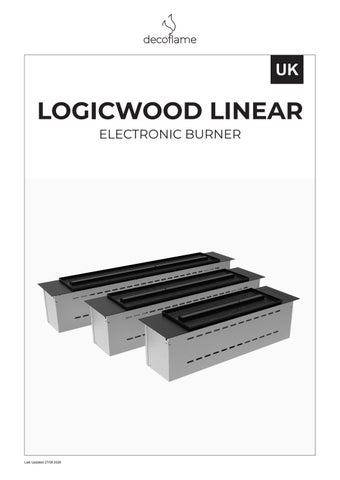
LOGICWOOD LINEAR ELECTRONIC BURNER
Last Updated 27/08 2026
READ BEFORE USE
IMPORTANT – READ BEFORE USE It is imperative that this manual is read carefully and in full before the fireplace is installed or operated. Keep this manual in a safe place for future reference.
INSTALLATION, OPERATION AND SAFETY The installation and operating instructions must be strictly followed, and all safety precautions described in this manual must be observed at all times. Failure to comply with these instructions may result in personal injury or damage to the fireplace.
LIABILITY Decoflame ApS cannot be held liable for any damage or injury resulting from non-compliance with the instructions contained in this manual.
PACKAGING Please retain the original packaging, as it is required should the fireplace need to be returned to the factory for service or repair.
FUEL REQUIREMENTS Only bioethanol with a pure alcohol content of 96.5–97.5 %, without additives or oils, may be used. The bioethanol must not be viscous or gel-like, and no substances may be added.
PRODUCT ORIGIN AND SAFETY All bioethanol fireplaces from Decoflame are designed, manufactured and quality-controlled in Denmark, with a strong focus on product safety and user-friendliness. Safety is paramount when working with open flames. All safety instructions described in this manual must be strictly observed.
ELECTRICAL CONNECTION If the fireplace is equipped with electronic components, it must be connected to an earthed power supply (220–240 V~ / 50 Hz / 1 kW).
3
CONTENTS
IMPORTANT – READ BEFORE USE
Page 3
GENERAL INFORMATION
Page 5
PACKAGING, DELIVERY & UNPACKING
Page 6
PRODUCT INFO - LOGICWOOD LINEAR BURNER
Page 8
BUILT-IN INSTALLATION
Page 10 Wall Construction Requirements
Page 10
Preparation of Wall
Page 11
Cut-Out Requirements
Page 12
Burner Installation Procedure and Log set placement
Page 14
GENERAL SAFETY
Page 24
OPERATIONAL SAFETY – DO NOT
Page 25
OPERATING INSTRUCTIONS
Page 26 Control System & Operation
Page 20
Remote Control
Page 28
App Control
Page 30
FUEL FILLING & EMPTYING
Page 31
ERROR MESSAGES & TROUBLESHOOTING
Page 33
MAINTENANCE
Page 34 Maintenance & Cleaning
Page 34
Disposal & Sorting
Page 35
COMPLAINTS, WARRANTY & SERVICE
Page 36
BIOETHANOL
Page 37
SYMBOLS EXPLANATION
Page 39
4
GENERAL INFORMATION
GENERAL INFORMATION Decoflame bioethanol fireplaces are developed as highquality interior products that combine contemporary design with functional fire technology. The fireplaces are intended for indoor use and are designed to create atmosphere and visual warmth as a decorative element in residential and commercial environments.
DESIGN AND MANUFACTURING All Decoflame bioethanol fireplaces are designed, manufactured and quality-controlled in Denmark. The development process focuses on precision engineering, durability and consistent product quality. Each fireplace is produced using carefully selected materials and components to ensure long-term reliability and safe operation.
INTENDED USE The fireplace is intended for use as a decorative fire feature. It is designed to supplement existing heating sources and must not be considered a primary heat provider. The fireplace must only be used in accordance with the instructions and limitations described in this manual.
PRODUCT VARIANTS AND CONFIGURATIONS Decoflame fireplaces are available in several configurations, including freestanding, wall-mounted and built-in solutions. Depending on the model, the fireplace may be equipped with a manual burner or an electronic burner system. The specific configuration and burner type are described in the relevant sections of this manual.
FUEL TYPE Decoflame fireplaces are designed exclusively for use with liquid bioethanol fuel that complies with the specified quality requirements. The use of alternative fuels, gel fuels or modified bioethanol products is not permitted and may result in unsafe operation or damage to the fireplace.
ELECTRICAL COMPONENTS Some Decoflame fireplaces are equipped with electronic components, including control systems, sensors and safety features. These fireplaces require connection to a fixed, earthed power supply. Electrical requirements and operating conditions are specified in the relevant sections of this manual.
STANDARDS AND COMPLIANCE Decoflame bioethanol fireplaces are developed in accordance with applicable European standards and general safety principles for open-fire products. The user is responsible for ensuring that installation and use comply with local building regulations and national requirements.
5
PACKAGING, DELIVERY & UNPACKING
PACKAGING, DELIVERY & UNPACKING The fireplace is delivered carefully packed to protect it during transport and handling. Proper inspection upon delivery and correct unpacking are essential to ensure that the fireplace is received in perfect condition and can be installed safely.
UNPACKING THE FIREPLACE Move the packaged fireplace as close as possible to its final installation location before unpacking.
PACKAGING TYPES Depending on the model and size, the fireplace may be delivered in one of the following packaging types:
For wooden crates, suitable tools such as a screwdriver or drill with the appropriate bit may be required. Always remove the fireplace slowly and place it on a stable, level surface.
Open the packaging carefully to avoid scratching or damaging the fireplace or its components.
• Cardboard box with protective polystyrene, placed on a pallet
Ensure that all protective packaging materials are removed and that all components are present. If any parts are missing or damaged, contact Decoflame immediately before proceeding with installation.
• Wooden crate with internal protective packaging, mounted on a pallet for safe handling The packaging is designed to protect the fireplace from impact and vibration during transport.
RETAINING THE PACKAGING The original packaging must be retained in case the fireplace needs to be returned to the factory for service or repair.
DELIVERY INSPECTION Upon delivery, the packaging must be inspected carefully for visible damage while the courier is present.
If the original packaging is no longer available, replacement packaging can be supplied by Decoflame upon request.
Any damage to the packaging must be noted immediately on the delivery note.
IMPORTANT – TRANSPORT DAMAGE If visible damage is found on the packaging, it is essential to: • Make a written remark on the delivery note before signing • Ensure that the remark is acknowledged by the courier Failure to note transport damage at delivery may result in loss of the right to make a claim. DO NOT – HANDLING AND UNPACKING
DOCUMENTATION OF TRANSPORT DAMAGE In the event of transport damage, Decoflame must be contacted immediately.
1
DO NOT
open the box or wooden crate using sharp objects.
2
DO NOT
flip the cardboard box or wooden crate onto its sides or top. Always follow the arrow markings
• A description of the damage
3
DO NOT
use hammers or other impact tools.
• A copy or photo of the delivery note with the damage remark and tracking number
4
DO NOT
use saws or similar cutting tools
5
DO NOT
smoke during unpacking, as residual bioethanol vapours may be present.
6
DO NOT
lift the fireplace by parts that are sensitive to bending or mechanical stress.
The following documentation is required: • Photos of all sides of the packaging • Photos of the fireplace and any visible damage
Transport damage must be reported within 3 working days from the date of delivery.
⚠
Failure to comply with the above instructions may result in damage to the fireplace or personal injury.
6
PACKAGING, DELIVERY & UNPACKING
CONTACT INFORMATION – DECOFLAME If you have any questions regarding delivery, packaging, transport damage or documentation, please contact Decoflame using the details below. Decoflame ApS Vang Mark 2 9380 Vestbjerg Denmark Tel.: +45 96 30 48 00 Email: logistics@decoflame.dk Email subject line: Order number (4–5 digits) Opening Hours: Monday–Thursday: 08:00–16:00 Friday: 08:00–15:30 (Danish time) Decoflame refers to its General Sales and Delivery Terms. If you have any questions or uncertainties, please contact Decoflame or your local retailer.
7
PRODUCT INFORMATION - LOGICWOOD LINEAR ELECTRONIC BURNER
THE CONTENTS OF THE BOX A
B
C
D
E
F
G
A
LogicWood Linar Burner
1 pc
B
Ceramic logs
1 pc
C
Base Ember Glass - Top Ember Glass
2 pc
D
Ember Fibre
1 pc
E
External fuel pump
1 pc
F
Remote control
1 pc
G
Manual
1 pc
H
Product identification label
1 pc
H UK
LOGICWOOD LINEAR ELECTRONIC BURNER
Last Updated 18/05 2026
LOGICWOOD LINEAR ELECTRONIC BURNER Denver LogicWood Linear is a fully integrated electronic bioethanol burner designed for built-in fireplace applications. The burner is developed for controlled combustion, stable flame performance and advanced operational safety in indoor installations.
Operational parameters are continuously supervised. In the event of abnormal conditions, the system will automatically interrupt operation. Fuel refilling is carried out using the supplied external electronic pump with quick-connection interface. The closed refilling system ensures controlled fuel transfer and minimises the risk of spillage or vapour exposure.
The system incorporates an electronically regulated fuel supply and an automated ignition and shutdown sequence. Flame intensity can be adjusted across five flame levels and ECO mode., ensuring consistent heat output and operational stability across all available sizes.
The burner is designed for installation in non-combustible constructions and must be integrated in accordance with the installation requirements specified in this manual.
The burner is equipped with integrated safety systems including:
It is intended exclusively for use with approved bioethanol (96.5–97.5%) and is not designed as a primary heating appliance.
• Automatic emergency shut-off • Continuous fuel level monitoring
For detailed fuel requirements and handling instructions, see section “Bioethanol”.
• Spill detection system • CO₂ monitoring (air quality supervision) • System self-diagnostics
8
PRODUCT INFORMATION - LOGICWOOD LINEAR ELECTRONIC BURNER
GENERAL INFORMATION Model:
LogicWood Linear
Flame Levels:
5 + ECO
Operation Type:
Electronic
Fuel type:
Bioethanol 96.5% – 97.5%
DESIGN & MATERIALS Material:
Stainless steel / Powder-coated aluminium
Finish:
Black powder coating
INSTALLATION REQUIREMENTS Power Supply:
230 V AC (220 V compatible), 50–60 Hz, earthed connection
Installation Environment:
Indoor
PHYSICAL SPECIFICATIONS MODEL
WIDTH (MM)
HEIGHT (MM)
DEPTH (MM)
720 LogicWood Linear
920
207
215
1120
WEIGHT (KG)
FLAME TRAY (MM)
19
450
25
650
29
850
TECHNICAL OVERVIEW
MODEL
720
920
1120
Capacity (liters)
5.3
6.6
8.3
Nominal Heat Output (kWh)
2.9
3.9
5.6
Burn Time at Maximum Level (hours)
10.2
9.5
8.3
Min. Room Size (m³)
62
85
108
9
POSITIONING & INSTALLATION
BUILT-IN INSTALLATION Electronic bioethanol burners are designed for integration into custom-built fireplace constructions. Built-in installation places specific requirements on: • Wall construction • Structural stability • Recess sealing • Ventilation control • Electrical connection All requirements in this section must be fully complied with.
ℹ NOTE
Non-compliant installation, incorrect recess construction, insufficient ventilation, unsealed penetrations or use of combustible materials may result in overheating, unstable combustion, automatic safety shutdown, malfunction and voiding of the warranty.
❌ DO NOT!
WALL CONSTRUCTION REQUIREMENTS The burner must be installed exclusively in non-combustible constructions.
NO
Approved materials include:
Do not install the burner in a wall construction that is open above and below the recess. Open vertical cavities may create uncontrolled internal convection inside the wall structure, which can destabilise the flame and activate safety shutdown.
• Concrete • Brick / masonry • Steel
The recess must not function as a ventilation shaft or chimney.
• Certified fire-rated building boards Combustible materials such as wood, MDF, plywood, particle board or similar must not be exposed within the installation recess unless fully protected by a certified noncombustible barrier in accordance with applicable building regulations.
YES
✅ DO
Install the burner in a closed wall construction. The recess above and below the burner must be fully enclosed to prevent internal air circulation within the wall structure.
The surrounding construction must: • Be dimensionally stable • Resist heat accumulation • Maintain structural integrity over time
YES
✅ DO (Solid Wall)
The burner may be installed directly in a solid non-combustible wall (e.g. brick or concrete) using the specified cut-out dimensions. Solid constructions prevent internal air movement and provide stable operating conditions.
10
POSITIONING & INSTALLATION
PREPARATION OF WALL The built-in recess must be constructed as a sealed installation volume.
❌ NOT APPROVED
The upper, lower and side sections of the recess must be fully closed and sealed to prevent uncontrolled air circulation inside the wall structure. The burner must not draw air from: • Concealed wall cavities • Floor voids • Ceiling spaces
1. Combustible material inside recess (not permitted).
2. Cable penetration not sealed.
3. Side sections not sealed against false draft.
4. Bottom of recess not sealed, allowing air leakage.
• Hollow wall structures Uncontrolled internal airflow may: • Disturb flame stability • Affect combustion behaviour • Trigger safety monitoring systems • Cause automatic shutdown • Create a fire hazard Cable penetrations must be sealed using fire-resistant sealant or equivalent approved materials. Seal all openings tightly to eliminate false draft.
✅ APPROVED
⚠
IMPORTANT
1. Hermetic sealing at top, sides and bottom. Continuous sealed base surface.
The recess must be hermetically sealed at both the top and the sides to prevent false draft. See the green marking.
2. Properly spaced and sealed cable routing. Grounded 3-pin power connection positioned outside heat zone.
Burner
3. Dimensionally stable and level recess walls. Cross-measurements must be level and aligned to ensure structural stability.
11
POSITIONING & INSTALLATION
CUT-OUT REQUIREMENTS The recess dimensions shall correspond to the technical specifications for the selected burner model and size.
VERTICAL DIMENSION (HEIGHT) The recess height shall allow full insertion of the burner housing while ensuring that the top plate rests evenly on the finished surface without mechanical stress.
Installation shall be based on the applicable technical documentation, including the dimensional principle drawings provided for the specific model.
A minimum vertical clearance of 250 mm must be maintained from the underside of the burner top plate to the bottom of the recess.
If the relevant drawings are not available, they must be obtained from Decoflame or an authorised retailer prior to construction. Installers are responsible for verifying all required measurements before commencing work.
This clearance ensures: • Correct positioning of the grounded power outlet •
Safe cable routing
DIMENSIONAL CALCULATION PRINCIPLE The vertical installation principles are defined by fixed dimensional values for the burner construction.
• Service accessibility
The horizontal dimension (width) varies according to the selected burner size.
📐 An active earthed power outlet shall be installed inside
Insufficient clearance may obstruct electrical connection and future servicing.
the recess, positioned at the bottom right-hand side. The outlet should be located below tank level (i.e. below 160 mm) to ensure correct connection and service access.
The recess width shall be calculated using one of the following reference methods:
📐 A recommended 500 mm of free space above the
Method A: Recess width = Top plate width (burner) − 15 mm
fireplace is required, along with a minimum of 250 mm of free space below the fireplace, to allow the burner to be lowered and handled without obstruction.
Method B: Recess width = Base housing width (burner) + 11 mm
INSTALLATION DEPTH The installation depth must allow the burner housing to seat fully within the recess while ensuring stable and level support.
These tolerances define the required installation clearance and ensure correct seating of the burner without mechanical stress.
The burner must not be forced into the recess. All internal corners of the recess shall be 90°. All supporting surfaces must be level and dimensionally stable.
BURNER DIMENSIONS (REFERENCE VALUES): Top plate width (varies by model)
BURNER FIXED HEIGHT/DEPTH (REFERENCE): Top plate depth 215 mm
Base housing width (varies by model)
Base housing height 207 mm
RECESS WIDTH (CUT-OUT RESULT):
Base housing depth 177 mm
A: Recess width = Top plate width (burner) − 15 mm
RECESS DEPTH (CUT-OUT RESULT):
Stikkontakt
Min. recess height 300 mm
B: Recess width = Base housing width (burner) + 11 mm
12
Recess depth 200 mm
POSITIONING & INSTALLATION
STRUCTURAL HEIGHT ABOVE RECESS In solid masonry or other non-combustible built-in constructions, the recess must include sufficient structural height above the burner opening. Where no steel plate, heat shield or prefabricated casing is installed above the recess, a minimum structural height of 500 mm above the burner opening shall be maintained. This requirement ensures controlled heat migration within the surrounding structure and forms part of the overall recess dimensioning principles described in this section. Insufficient structural height may result in:
Min. 500 mm
• Heat accumulation • Thermal stress in surrounding materials • Cracking of masonry or plaster joints over time
ℹ NOTE
When installed in a Decoflame casing, installation must follow the specific casing installation manual supplied with the product.
INSTALLATION BELOW TV OR HEAT-SENSITIVE EQUIPMENT Installation of televisions, electronic equipment or other heat-sensitive components directly above the burner is not recommended due to natural upward heat migration.
The installer is responsible for verifying that the selected configuration prevents excessive heat exposure to mounted equipment.
If installation above the burner is required, the following minimum clearances shall be observed:
Decoflame assumes no responsibility for damage to electronic devices installed above the burner.
• Minimum vertical distance: 800 mm (open installation without shielding) • Minimum vertical distance: 200 mm when an approved deflecting shelf or shielding construction is installed
min. 800 mm min. 200 mm
min. 300 mm
13
POSITIONING & INSTALLATION
BURNER INSTALLATION PROCEDURE This procedure applies after the recess has been completed and verified in accordance with the dimensional, structural and electrical requirements defined in this manual and the applicable technical drawing.
STEP 1 – Verification Verify that the recess:
STEP 5 – Ember glass placement First distribute the Base Ember Glass evenly across the Ember Light openings in the decoration tray.
• Is clean and free from dust, debris and installation residue • Complies with the specified dimensions
Then lightly distribute the Top Ember Glass on top of the Base Ember Glass as shown in the QR guide video.
• Contains a correctly installed and accessible grounded power outlet (230 V AC (220 V compatible), 50–60 Hz) • Has level and dimensionally stable supporting surfaces
Placement of the Ember Glass must follow the instructions shown in the QR guide video.
identified.
⚠ Do not place Ember Glass on the Flame tray.
⚠ Do not proceed with installation if any deviation is STEP 2 – Electrical Preparation Ensure the power supply is switched OFF before connection.
Connect the burner power cable to the grounded power outlet inside the recess. Ensure that:
STEP 6 – Ceramic log placement Place the ceramic logs as shown in the supplied placment guide.
• The cable is not routed across sharp edges • The cable is not twisted, pinched or under tension
Ensure that:
• The connection does not interfere with proper seating of the burner
• The ceramic logs are positioned securely and stably • The upper logs are supported by other logs and not placed directly on the Flame tray
STEP 3 – Insertion of Burner Carefully lower the burner vertically into the recess.
• The flame openings remain visible and unobstructed
⚠ Do NOT tilt the burner during insertion.
• The flame path remains open along the Flame tray
⚠ Incorrect placement of the ceramic logs may result in
Ensure that:
unstable flame behaviour, operational malfunction, damage to the ceramic logs or safety shutdown.
• The base housing seats evenly within the recess • The top plate rests fully and evenly on the finished surface
See placment guide.
• No mechanical resistance or obstruction is encountered
⚠ The burner must not be forced into position.
STEP 7 – Ember Fibre placement Carefully distribute small amounts of Ember Fibre between the ceramic logs, along the Flame tray opening.
STEP 4 – Final Positioning Check Verify that: • The burner is horizontally aligned
The Ember Fibre is intended to be exposed to the flame area to create the ember glow effect.
• The top plate sits flush with the surrounding finished surface
Placement of the Ember Fibre must follow the instructions shown in the QR guide video.
• No mechanical stress is applied to the base housing
⚠ Ensure that excessive amounts are not concentrated directly above the ignition area.
14
POSITIONING & INSTALLATION
LOG SET PLACEMENT GUIDE - LOGICWOOD BURNER 720
⚠ The flame openings remain visible and unobstructed =
1
2
3
15
POSITIONING & INSTALLATION
4
5
6
7
8
Scan the QR code for the placement guide. 16
POSITIONING & INSTALLATION
LOG SET PLACEMENT GUIDE - LOGICWOOD BURNER 920
⚠ The flame openings remain visible and unobstructed =
1
2
3
17
POSITIONING & INSTALLATION
4
5
6
7
8
18
POSITIONING & INSTALLATION
9
10
11
Scan the QR code for the placement guide. 19
POSITIONING & INSTALLATION
LOG SET PLACEMENT GUIDE - LOGICWOOD BURNER 1120
⚠ The flame openings remain visible and unobstructed =
1
2
3
20
POSITIONING & INSTALLATION
4
5
6
7
8
21
POSITIONING & INSTALLATION
9
10
11
12
13
22
POSITIONING & INSTALLATION
14
15
16
17
18
Scan the QR code for the placement guide. 23
GENERAL SAFETY
GENERAL SAFETY Bioethanol fireplaces involve the use of open flames and must therefore always be operated with a high level of care and attention. Correct use in accordance with this manual is essential to ensure personal safety, safe surroundings and reliable operation of the fireplace.
IN CASE OF FIRE – EMERGENCY INSTRUCTIONS In the event of a fire, remain calm and act according to the following guidelines:
OPEN FIRE AND RESPONSIBILITY The fireplace produces a real, open flame. The user is responsible for operating the fireplace in a safe and controlled manner at all times. Only adults may operate the fireplace, and it must never be left unattended while in use.
Suitable extinguishing media include carbon dioxide (CO₂), dry chemical powder, foam or alcohol-resistant foam, and water spray (mist only). For minor fires, use CO₂, dry chemical powder, alcohol-resistant foam or carefully smother the flames using a moistened cloth.
CHILDREN AND PETS Children and pets must always be supervised when the fireplace is in operation. The fireplace must be positioned and used in a way that prevents contact with flames, hot surfaces or other potentially hazardous parts.
For major fires, use alcohol-resistant foam or water spray. Do not use a water jet. Do not rinse the floor with water, as bioethanol vapours may spread and re-ignite.
VENTILATION AND ROOM AIR QUALITY Adequate natural ventilation of the room is required during operation of the fireplace. Fresh air supply must be ensured without creating draughts, as excessive air movement may affect flame behaviour and combustion stability.
If the fire is assessed to be out of control, contact the fire authorities immediately.
ℹ NOTE
Persons with respiratory conditions or asthma are advised to keep a window slightly open during operation of the fireplace.
HOT SURFACES During operation, parts of the fireplace, including the burner and any protective glass, may become hot. Care must be taken to avoid contact with hot surfaces during and after use, until the fireplace has fully cooled down.
DECORATIVE PURPOSE The fireplace is intended primarily for decorative purposes. It is designed to supplement existing heating sources and must not be considered or used as a primary heat source.
FIRE SAFETY AND PREPAREDNESS Appropriate fire-extinguishing equipment must always be readily available when operating the fireplace. The user must be familiar with basic fire safety principles before using the fireplace.
24
⚠
⚠
OPERATIONAL SAFETY – DO NOT
OPERATIONAL SAFETY – DO NOT The following safety instructions apply during operation of the fireplace. Failure to comply with these instructions may result in fire, personal injury or damage to the fireplace. Bioethanol fireplaces involve real, open flames and must always be operated with care and common sense.
DO NOT – DECORATIVE MATERIALS AND PLACEMENT RESTRICTIONS
DO NOT – FUEL HANDLING AND REFILLING 1
DO NOT
light the fireplace if the burner has been overfilled.
2
DO NOT
refill the burner until the temperature has dropped below 40 °C.
3
DO NOT
refill the burner while it is in use or still hot from previous operation.
4
DO NOT
smoke when filling or handling bioethanol, as it is highly flammable.
5
DO NOT
mix bioethanol with other fuels or add additives, oils or scents.
1
DO NOT
place any objects on top of the burner.
2
DO NOT
decorate the burner with ceramic pebbles, stones, logs or other items unless explicitly approved by Decoflame.
3
DO NOT
place stones or pebbles on the burner, as they may crack and cause injury or damage.
4
DO NOT
place flammable materials, clothing or objects on or near the fireplace.
5
DO NOT
place valuable items, paintings or electronic equipment such as TV screens or speakers above the fireplace, as rising heat may cause damage.
DO NOT – FIRE BEHAVIOUR
1
DO NOT
attempt to extinguish the fire by blowing into the flames.
2
DO NOT
blow into the flames, as this may cause the fire to spread and become uncontrollable.
3
DO NOT
touch the flames at any time.
DO NOT – USE AND HANDLING
DO NOT – MAINTENANCE AND CLEANING 1
DO NOT
perform cleaning, maintenance or adjustments while the fireplace is hot or in operation.
2
DO NOT
use water, solvents or aggressive cleaning agents on the burner or fireplace components unless specified in this manual
25
1
DO NOT
use the fireplace or burner as a barbecue or cooking device.
2
DO NOT
cover the fireplace while it is lit or still hot.
3
DO NOT
touch metal parts, the burner or glass components during operation or until the fireplace has fully cooled down.
4
DO NOT
modify the fireplace or any of its components.
OPERATING INSTRUCTIONS - LOGICWOOD ELECTRONIC BURNER
Flame Tray
LED Ember Lights
Glow Plug Igniter
Control Panel
LCD Display
On/Off Switch
Fuel Inlet Connection
OPERATING INSTRUCTIONS This chapter describes the operation of burners equipped with the Decoflame LogicWood electronic burner. Always read and follow all safety instructions before operating the burner. The LogicWood burner is electronically controlled and designed to ensure safe and controlled ignition, flame regulation and shutdown.
Power Plug Socket Fuel Inlet Socket
The burner can be operated via the integrated Control Panel, remote control, or the Decoflame App, depending on the model configuration.
Release Button Main Power On/Off
CONTROL SYSTEM & OPERATION The burner is operated via the Operating Panel, which provides access to the main power switch, display, fuel filling connection, electronic pump interface and the integrated Control Panel. The Control Panel consists of the control buttons used for daily operation, including ignition, flame regulation and shutdown.
LCD Display
The burner is supplied with a remote control, allowing the same operating functions available via the Control Panel to be operated wirelessly. The control system manages ignition, flame regulation and continuous safety monitoring automatically. Control Panel
ℹ NOTE
The service ports are reserved for authorized Decoflame service personnel only.
Service Ports
OPERATING PANEL
26
OPERATING INSTRUCTIONS - LOGICWOOD ELECTRONIC BURNER
DISPLAY STATES & STATUS INDICATIONS The display shows the burner’s current operating state, system status and relevant messages. The indications may vary depending on the operating phase and system conditions.
FIRST START – SWITCHING THE POWER SUPPLY ON Before operating the burner, ensure that it is correctly installed and that all safety requirements described in this manual have been fulfilled. Press the MAIN ON/OFF BUTTON on the Operating Panel to activate the power supply to the burner.
E
Once activated, the power supply should normally remain switched on.
ℹ NOTE
The power supply should only be switched off under the following circumstances:
Display (Boot screen): • Bluetooth code • IP address
• If the burner will not be used for an extended period of time • In the event of an emergency
CURRENT STATE:
FIG 1. SWITCHING THE DISPLAY ON Press the ON/OFF button on the control panel to switch the display on.
FIG 2. SWITCHING THE FLAMES ON / OFF Press the START/STOP button on the control panel TO START the ignition process. After approximately 3 minutes, the first flames will appear around the centre of the Flame tray. After an additional 3 minutes, the burner will have heated up and flames will extend across the full width of the Flame tray. Once ignition is complete, the display will show FIRE ON. The flame height can now be adjusted.
READY
The burner is ready for operation. The flames can be switched on (see 2).
WARMING UP
The burner is in the start-up sequence and is heating up. The status will automatically change to FIRE ON once ignition is complete.
FIRE ON
The burner is operating normally and the start-up process is complete. The flame level can now be adjusted (see Fig 3).
TURNING OFF
The burner is shutting down.
CO₂ ELEVATED
The CO₂ level has remained above 3,500 ppm for more than 60 seconds. The flame is automatically reduced to level 1.
ELEVATED CO₂ LEVEL If the CO₂ level remains above 3,500 ppm for more than 60 seconds, the flame is automatically reduced to level 1 and cannot be increased until the CO₂ level falls below 3,500 ppm. Ventilate the room when the CO₂ warning is displayed. At 5,000 ppm or above, the burner automatically shuts down.
To switch the FLAMES OFF, press the START/STOP button again. FIG 3. ADJUSTING THE FLAME LEVEL Press the − or + buttons to decrease or increase the flame height.
ℹ NOTE
ℹ NOTE
Automatic flame reduction is a normal safety function and does not indicate a burner fault. CO₂ monitoring does not replace adequate room ventilation.
When the + or - button is pressed and released briefly, the flame level will decrease / increase by one step. This adjustment is only performed when the button is pressed for a short duration.
ERROR MESSAGES:
Adjust the flame height gradually and allow the burner to stabilise between adjustments.
FIG 1
Display (Main screen): • Current state • Error messages • Fuel level • Flame level • CO2 message
FIG 2
2. FIG 3
27
CALL SERVICE
Internal system fault detected. The burner is locked and cannot be started or reset. Contact authorised service personnel.
NO FLAME
Ignition was unsuccessful. Contact authorised service personnel.
TOO HOT TO FILL
The burner is too hot to refill. Refilling is only possible once the burner has cooled down.
HEATING ERROR
A heating system fault has been detected. Contact authorised service personnel.
LOW FUEL
The fuel level is low. Refill the bioethanol tank.
SPILL DETECTED
Fuel spillage has been detected. Contact authorised service personnel.
OPERATING INSTRUCTIONS - REMOTE CONTROL
REMOTE CONTROL The LogicWood electronic burner may be operated using the supplied remote control, depending on model configuration.
CONNECT / RESTART REMOTE CONTROL If the remote control is not responding, it may be necessary to reconnect it to the burner.
The remote control provides convenient access to the main operating functions of the burner and mirrors selected functions of the integrated control panel.
Follow the procedure below:
The remote control communicates wirelessly with the burner and is intended for everyday operation within normal indoor range.
REMOTE CONTROL FUNCTIONS The following functions are available via the remote control: • SWITCHING THE DISPLAY ON / OFF Powers the burner display on or off.
1.
Turn on the burner using the main power switch.
2.
Press and hold OK + 2 on the remote control for approximately 3 seconds until the red indicator light starts flashing.
3.
Press and hold the OFF button on the burner for approximately 14 seconds until the display turns off. Release the button once the display switches off.
4.
The burner will restart automatically. The remote control is now connected to the burner.
ℹ NOTE
If the connection procedure fails, repeat the steps above. Ensure that the burner remains powered during the process.
• STARTING AND STOPPING THE FLAMES (START / STOP) Initiates ignition of the flames or shuts them down in a controlled manner. • ADJUSTING FLAME LEVEL (LEVELS 1–5 + ECO) Allows step-by-step adjustment of the flame height within the available range. • STARTING / STOPPING THE LED EMBER LIGHTS Activates or switches off the LED Ember Lights. • ADJUSTING LED EMBER LIGHT LEVELS (1–3) Allows step-by-step adjustment of the LED Ember Light intensity between three available levels.
Scan the QR code for the connect / restart guide.
• CHILD LOCK (1+2) The child lock is activated by pressing button 1 and 2 simultaneously for 1–3 seconds. When the child lock is active, remote control operation is disabled. The child lock must be deactivated on the remote control or by restarting the burner.
ON/OF DISPLAY
START/STOP FLAMES
CHILD LOCK 1+2
USING THE REMOTE CONTROL Ensure that the burner is connected to power and in standby mode before using the remote control. Point the remote control towards the burner and press the desired function button. After input, the system may respond with a short delay while internal safety checks are performed.
EMBER LIGHTS LEVEL ADJUST
START/STOP LED EMBER LIGHTS
Allow the system to stabilise between adjustments and avoid pressing multiple buttons simultaneously.
ℹ NOTE
FLAME LEVEL ADJUSTMENT 1 - 5 + ECO
The remote control is intended for indoor use only. Always keep the remote control out of reach of children when not in use. If the burner does not respond to remote control input, operate the burner via the control panel and refer to the troubleshooting section of this manual.
28
OPERATING INSTRUCTIONS - REMOTE CONTROL
BATTERY INFORMATION The remote control is powered by an internal CR2032 lithium battery. If the remote control does not respond or the response becomes weak, the battery must be replaced. Always replace the battery with the same type (CR2032) as specified by Decoflame. Incorrect battery type may result in malfunction. Dispose of used batteries in accordance with local regulations.
BATTERY HOLDER place battery in holder
Press here when putting the holder back in place
BATTERY COVER pull out of the bottom
29
OPERATING INSTRUCTIONS - APP CONTROL
APP CONTROL TIMER FUNCTION The burner can be set to switch off automatically after a selected time period.
The burner can be operated via the Decoflame App using a Bluetooth connection. The app provides access to selected operating functions and displays current system status information.
The remaining time is displayed in the app during operation. STATUS INFORMATION The app displays current operating status, fuel level and estimated remaining burn time.
CONNECTING THE APP Before using the app, ensure that the burner is powered and ready for operation. • Download the Decoflame App from App Store or Google Play
SETTING THE TIMER VIA THE APP The timer function can be set via the Decoflame App.
• Activate Bluetooth on your mobile device
1. Open the app and ensure that the burner is connected.
• Open the app and follow the on-screen instructions
2. Navigate to the main control screen.
• Select the burner when it appears in the device list
3. Access the timer function (See Fig. 1). 4. Set the desired time period (See Fig. 2)
AVAILABLE FUNCTIONS The app provides access to the following operating functions:
5. Confirm the timer setting (See Fig. 2) Once activated, the timer will be displayed in the app. The burner will switch off automatically when the set time has elapsed.
START / STOP The flames can be started and stopped via the app.
ℹ NOTE
FLAME LEVEL The flame level can be adjusted from level 1 to 5, including ECO mode.
If multiple control methods are used, the latest input overrides previous settings.
ECO MODE ECO mode automatically regulates the flame between level 1–5 during operation.
The app operates via Bluetooth and requires the user to be within range of the burner.
TIME LEFT DISPLAY
SET TIMER FUNCTION
CONFIRM TIMER
TIMER FUNCTION
Fig. 1
Fig. 2 30
FUEL FILLING AND DRAINING OF BIOETHANOL
FUEL FILLING & EMPTYING
ℹ NOTE
This burner is equipped with an electronic pump system designed for safe and controlled handling of bioethanol. Only approved bioethanol with an alcohol content of 96.5–97.5 % may be used. Refer to the Bioethanol chapter of this manual for further information.
BIOETHANOL FUEL FILLING PROCEDURE Before filling bioethanol, ensure that the burner is connected to the power supply and switched ON using the main power switch on the burner. The flames must be switched OFF before filling.
FILLING PROCEDURE 1. Switch on the main power switch on the burner. 2. Insert the filling nozzle firmly into the fuel inlet on the burner. 3. Connect the power plug from the electronic pump to the designated socket on the burner. 4. Place the rubber hose from the pump into the Bioethanol container.
•
The electronic burner continuously monitors the fuel level. If the fuel level is insufficient, the system will prevent ignition.
•
Bioethanol must not be filled while the burner is in operation.
•
The ignition process will not start if the system detects that the pump is connected.
•
If the pump is connected while the burner is operating, the system will shut down automatically.
•
Bioethanol must never be poured onto a hot burner or into open flames.
•
Smoking is strictly prohibited during filling and in the immediate vicinity.
•
If an unexpected situation occurs, the entire system can be switched off immediately using the main power switch on the burner.
•
Allow any spilled bioethanol to evaporate completely before operating the burner.
5. Switch on the pump. The pump will automatically stop when the maximum fuel level is reached. 6. Remove the filling nozzle by pressing the release button next to the fuel inlet.
Power Plug Socket Fuel Inlet Socket
Release Button Power on/off
Scan the QR code for the refill guide.
31
FUEL FILLING AND DRAINING OF BIOETHANOL
ℹ NOTE
DRAINING OF BIOETHANOL The electronic pump system can also be used to drain bioethanol from the burner. Draining of the fuel tank is required if the burner is to be moved, transported, stored, or returned to Decoflame for service or repair. The same pump used for filling is used for draining by repositioning the filling nozzle on the hose.
DRAINING PROCEDURE The burner must be connected to the power supply and switched ON using the main power switch. The flames must be switched OFF during the entire draining process. 1. Cut and remove the small black cable tie securing the filling nozzle to the hose. The cable tie must be removed before the filling nozzle can be detached.
•
The fuel tank must never be drained while the burner is in operation.
•
The ignition process will not start if the system detects that the pump is connected.
•
If the pump is connected while the burner is operating, the system will shut down automatically.
•
Smoking is strictly prohibited during draining and in the immediate vicinity.
•
Avoid spillage of bioethanol. Allow any spilled bioethanol to evaporate completely.
•
If an unexpected situation occurs, the entire system can be switched off immediately using the main power switch on the burner.
2. Detach the filling nozzle from the hose and attach it to the opposite end of the hose – the end normally placed into the bioethanol container during filling. 3. Insert the filling nozzle into the fuel inlet on the burner. 4. Connect the power plug from the electronic pump to the designated socket on the burner. 5. Place the free end of the hose into a suitable and approved bioethanol container. 6. Switch on the pump. Bioethanol is transferred from the fuel tank to the external container. 7. Monitor the process. The pump will stop automatically when the fuel tank is empty. 8. Remove the filling nozzle by pressing the release button next to the fuel inlet. 9. Reattach the filling nozzle to the opposite end of the hose so it is ready for future filling. Secure the filling nozzle with a cable tie if required.
Scan QR code for procedure.
32
ERROR & TROUBLESHOOTING
ERROR MESSAGES & TROUBLESHOOTING GENERAL GUIDANCE • Always extinguish the flames before starting any troubleshooting.
This section describes the most common error messages and system states that may occur during operation of the electronic burner, together with the recommended corrective actions.
• Some error conditions require the system to cool down completely before it can be restarted.
If the problem cannot be resolved by following the instructions below, switch off the fireplace and contact your authorised dealer or Decoflame.
• Repeated or persistent error messages indicate that further technical assistance is required.
ERRORS
DESCRIPTION
REQUIRED ACTION
Tray High / Low
The fuel level in the burner tray is too high or too low, which may affect burner perfor mance.
Allow the fireplace to cool down. Restart the system. If the problem persists, contact your dealer.
Call Service
An internal system fault has been detected. The fireplace is locked for safety reasons and cannot be started or reset by the user.
Contact Decoflame or authorised service personnel. Reactivation is only possible after remote system access has been established.
Evap High / Low
The fuel level in the evaporation chamber is too high or too low, which may cause irregular vapour formation.
Allow the fireplace to cool down. Restart the system. If the problem persists, contact your dealer.
No Heat
The heating element does not generate heat, possibly due to a system fault.
Restart the fireplace after cooling. If the error remains, contact your dealer.
No Flame
The burner attempts to ignite but no flame is detected. This may be caused by fuel supply or ignition issues.
Restart the fireplace. If the problem persists, contact your dealer.
Flame Out
The fuel level is too low or the fuel tank is empty.
Do not switch off the power. Refill the fuel tank as described in section: Fuel Filling & Emptying.
Spill Detected
Liquid has been detected, possibly due to overfilling or leakage.
Allow spilled bioethanol to evaporate completely. Do not attempt ignition while a spill is present. Contact your dealer if the issue persists.
MCU Temp High
The controller temperature is too high, which may cause overheating or system shutdown.
Allow the fireplace to cool down completely before restarting.
Low Fuel
The fuel tank is nearly empty.
Refill the fuel tank as described in section: Fuel Filling & Emptying.
Remote Low
The battery level in the remote control is low.
Replace the battery in the remote control.
Sensor Error
One or more sensors are not functioning correctly.
Contact your dealer or Decoflame for service.
33
MAINTENANCE
MAINTENANCE & CLEANING Regular maintenance and correct cleaning are essential to ensure safe operation, optimal performance and long product life of the fireplace.
PERIODIC CHECKS • Ensure that ventilation openings are free from obstruction.
Before any cleaning is carried out, ensure that the fireplace is completely switched off and that all components have cooled down fully.
• Check that all visible components are intact and undamaged. • Verify that the remote control functions correctly and replace the battery if required.
GENERAL MAINTENANCE The fireplace is designed to require minimal maintenance during normal use.
WARNING
Glass components are made of toughened, heat-resistant glass. Both glass and metal parts exposed to flame heat may change colour or surface structure slightly over time. This is considered normal wear and does not constitute a product defect.
• The fireplace must never be cleaned while in operation or while hot. • Do not attempt to open or service internal components.
Regular visual inspection of the burner, glass components and surrounding surfaces is recommended to ensure that no damage, excessive soot or contamination is present.
• Servicing and repairs must only be carried out by authorised personnel.
CLEANING THE BURNER The burner must be kept clean and free of dust, debris and residues.
Failure to follow these instructions may result in damage to the fireplace and may void the warranty.
Clean the burner using a lint-free cloth or paper towel together with a non-abrasive cleaning agent, such as bioethanol or another alcohol-based product.
ℹ NOTE
When cleaning the Flame tray, special care must be taken to avoid contact with the filament. This delicate component can be easily damaged if touched.
CLEANING GLASS COMPONENTS Glass panels must be completely cooled before cleaning. Clean glass using a soft, lint-free cloth and a suitable, non-abrasive glass cleaner. Avoid scratching the glass surface.
CLEANING POLISHED STEEL SURFACES Polished steel surfaces must only be cleaned using a soft, clean cloth. Paper towels or rough materials may cause scratches and should not be used on polished surfaces.
34
⚠
MAINTENANCE
DISPOSAL & SORTING Decoflame bioethanol fireplaces are manufactured from aluminium, stainless steel, glass, copper, plastic and electronic components. At the end of the product’s service life, the fireplace must be disposed of in accordance with applicable local and regional regulations.
ELECTRONIC COMPONENTS Electrical and electronic components must be disposed of separately and in accordance with local regulations for electronic waste (WEEE). Electronic components must not be disposed of with household waste.
METAL AND GLASS COMPONENTS Metal and glass parts can generally be recycled. Handle glass components with care during disassembly and disposal. Sorting of materials must be carried out in accordance with local recycling guidelines.
ENVIRONMENTAL CONSIDERATIONS Most components of Decoflame bioethanol fireplaces are recyclable. Correct disposal and material sorting contribute to reduced environmental impact and responsible use of resources. For further information on correct disposal, contact your local waste disposal authority or recycling centre.
35
COMPLAINTS, WARRANTY & SERVICE
COMPLAINTS, WARRANTY & SERVICE WEAR PARTS The fireplace is designed for long service life when correctly installed, used and maintained.
Decoflame ApS provides a 24-month right of complaint, calculated from the date of purchase at Decoflame ApS. The right of complaint covers documented defects attributable to material or manufacturing faults.
The right of complaint does not apply to wear parts. Wear parts are components subject to natural wear during normal operation and therefore require regular inspection and replacement.
The right of complaint is a supplement to the buyer’s statutory rights under applicable Danish and EU legislation.
ℹ NOTE
Repair or replacement does not extend the complaint period.
Wear parts include:
The product must be purchased from an authorised Decoflame dealer and installed by an authorised service technician, where required.
• Seals
• Hoses (external filling pump and siphon system)
• Igniters • Heating element • CO₂ sensor
THE RIGHT OF COMPLAINT DOES NOT APPLY TO The right of complaint does not apply to conditions resulting from normal use, wear or external influences, including:
• Flame Tray Indicative replacement intervals:
• Cosmetic conditions (colour changes, patina, corrosion, oxidation, wear of glass and surface finishes)
• Hoses: after approx. 1,000 operating hours or 2–5 years • Igniters: after approx. 1,000 start/stop cycles or in case of malfunction
• Normal wear and ageing
• Heating element: replace as required
• Damage occurring after delivery (transport, storage or handling)
• CO₂ sensor: replace as required
• Damage caused by external influences (fire, flooding, frost, lightning, etc.) • Incorrect installation, incorrect use or lack of maintenance
All service work and replacement of wear parts must be carried out exclusively by a Decoflame ApS-approved or instructed service technician.
• Modifications or repairs carried out by unauthorised persons
Failure to comply with service and maintenance requirements may result in loss of the right of complaint.
• Use of non-original or non-approved components • Commercial use of the product
SERVICE & SUPPORT The service form must be completed via:
IN THE EVENT OF A COMPLAINT Complaints must be submitted to the dealer from whom the product was purchased.
• https://www.decoflame.dk/service • https://www.decoflame.com/service Contact Decoflame ApS for service: Telephone: +45 96 30 48 00 (extension 4)
The following documentation must be provided: • Order number or CE marking • Product serial number
Applicable complaint conditions are stated in Decoflame ApS’ General Terms of Sale and Delivery.
• Valid proof of purchase • Written description of the fault • Photographic documentation Decoflame ApS determines whether the complaint is justified and decides on the appropriate remedy. To ensure that the right of complaint is valid and active, the service form must be completed. See the section Service & Support.
36
BIOETHANOL
BIOETHANOL BIOETHANOL IS A HIGHLY FLAMMABLE FUEL AND MUST BE HANDLED WITH CARE.
STORAGE CONDITIONS Always follow the instructions on the bioethanol packaging.
This fireplace is designed to operate with liquid bioethanol fuel only. Improper fuel quality, unsafe handling or incorrect storage may result in fire, personal injury, property damage or malfunction.
• Store bioethanol securely and out of reach of children. • Store only in the original, correctly labelled container. • Keep the container tightly closed.
APPROVED FUEL QUALITY Only bioethanol with an alcohol concentration of 96.5–97.5 % (v/v), free from additives and oils, may be used.
• Store in a relatively cool, dry and well-ventilated area, away from ignition sources.
❗REQUIREMENT
• Keep away from oxidising agents and incompatible materials.
Use only liquid bioethanol of 96.5–97.5% alcohol purity. Do not use viscous, gel-like or scented products. Do not add oils, fragrances or any other substances.
• Take preventive measures against static electricity generation.
Bioethanol must be at normal room temperature before ignition. If the fuel is too cold, ignition may be difficult or unstable.
REQUIREMENT Bioethanol must be stored in a safe manner in accordance with applicable local regulations.
37
BIOETHANOL
GENERAL SAFETY PRECAUTIONS WHEN HANDLING BIOETHANOL
FIRST AID AND EMERGENCY GUIDANCE If bioethanol contacts eyes or skin, follow the instructions on the bioethanol packaging and seek medical guidance if symptoms persist.
Preventive measures: • Avoid inhalation of vapours.
If ingestion is suspected, contact local poison control / medical services immediately for further guidance.
• Avoid contact with eyes, skin and clothing. • Persons prone to skin allergy or respiratory disease should avoid direct contact with bioethanol.
CLASSIFICATION AND REGULATORY RESPONSIBILITY Denatured bioethanol is classified as:
• Follow general chemical handling precautions (hygiene, ventilation, protective measures).
• Flammable Liquid – Category 1B (flammability) • Class 3, Packing Group II (transport classification)
ℹ NOTE
If bioethanol is spilled, allow it to evaporate completely before operating the fireplace. Ventilate the room without creating draughts.
• UN 1170 (identification number) Bioethanol is regulated by various standards and regulations globally. Users must familiarise themselves with and comply with applicable requirements for lawful and safe storage, handling, decanting and use of this fuel.
FIRE PREVENTION MEASURES Due to the highly flammable nature of bioethanol, all fire safety precautions must be followed strictly.
RECOMMENDED FUEL Decoflame recommends using Decoflame bioethanol where available. For purchasing guidance and approved products in your market, contact your nearest Decoflame retailer.
• Protect the container from overheating. • Store bioethanol in a fire-resistant container and keep it out of reach of children. • Avoid contact with heat, sparks and open flames. • Keep away from incompatible materials such as metal or alkaline products. • Flash point: 13 °C Boiling point: 78 °C • The fireplace may be difficult to ignite if the bioethanol temperature is below room temperature.
DO NOT
⚠
PROHIBITED USE
⚠
• Do not smoke when handling, transferring or filling bioethanol.
The following actions are strictly prohibited and will void the warranty:
• Do not pour bioethanol onto a hot fireplace or into open flames.
• Mixing bioethanol with other fuels • Adding additives, oils, scents or colouring agents
• Do not handle bioethanol near heat sources, sparks or open flames.
• Using fuels other than approved bioethanol (96.5–97.5 %) • Using bioethanol for purposes other than fireplace operation
38
SYMBOL EXPLANATION
SYMBOL EXPLANATION The symbols used in this manual are intended to provide clear and immediate communication of important safety information, warnings and operating instructions. The symbols highlight actions that must not be performed, conditions requiring special attention, and general safety and health hazards associated with the use of the bioethanol fireplace. All symbols must be fully understood and strictly observed. Failure to comply with the indicated instructions may result in fire hazard, personal injury, malfunction and loss of warranty and right of complaint. If a symbol appears without accompanying text, its general meaning applies as defined in this symbol explanation.
Do not refill directly onto the flames
Do not refill a hot burner
Do not place the bioethanol fireplace close to combustible materials
Protect the fireplace from draughts
No smoking
Do not blow into the flames
Do not touch the flames
Health hazard
Keep suitable fire extinguishing equipment available
Follow instructions regarding fuel and fire blanket
Warning – combustible material
39
Installation and use of the fireplace must comply with all applicable national and local regulations, including requirements from local fire authorities. All specifications are subject to product tolerances and ongoing technical development. Typographical errors and technical inaccuracies are reserved. This manual may be translated into other languages. In the event of discrepancies or differences in interpretation, the English version shall prevail. Decoflame ApS reserves the right to make changes to products and documentation without prior notice. For further information, please refer to Decoflame’s General Terms of Sale and Delivery.
Decoflame ApS
|
Vang Mark 2, 9380 Vestbjerg, DK
|
+45 9630 4800
|
info@decoflame.dk