ARTIGO TÉCNICO Filipe Campos Meira Castro, António Fernando Macedo Ribeiro, Univ. do Minho, Departamento de Electrónica Industrial, Guimarães, Portugal [11] filipemeiracastro@gmail.com, fernando@dei.uminho.pt Günther Starke, Christoph Dreyer APS – European Center for Mechatronics, Aachen, Germany [12] {starke, dreyer}@aps-mechatronik.de
MOBILE ROBOT ELECTRONIC SYSTEM WITH A NETWORK AND MICRO-CONTROLLER BASED INTERFACE ABSTRACT This paper describes the electronic system used to a mobile tank-robot and the network and micro-controlled based interface proceeding to drive it. Key Words: Tank Robot, Client/Server, Qt, Atmega16, Encoder, MD03 Driver, I2C (Inter Integrated Circuit)
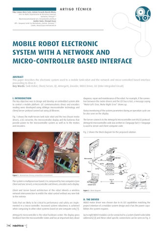
I. INTRODUCTION The key objective was to design and develop an embedded system able to control a mobile platform. I2C communications drives and encoders reading were developed using ATMega microcontroller technology and Client/Server protocol carried out using Qt libraries. Fig. 1 shows the multi-terrain tank style robot and the two chosen motor drivers, a DC converter, the microcontroller display and the batteries that provide power to the microcontroller system as well as to the motors and encoders.
diagnose, repair and maintenance of the robot. For example, if the connection between the motor drivers and the I2C bus is lost, a message saying “Motor Left: Error, Motor Right: Error” shows up. Status monitoring of the system parameters during an operation cycle can be also seen on the display. The Server connects to the Atmega16 microcontroller over RS232 protocol. Atmega16 microcontroller code was written in C language but C++ language is used to Server and Client computer code. Fig. 2 shows the block diagram for the proposed solution.
Figure 1 . Autonomous Driving competition environment.
The system is multiprocessor based, it is composed by two computers (one Client and one Server), a microcontroller and drivers, encoders and a display. Client and Server based architecture of this robot inherits a wireless network interconnection to entitle the robot control without any wire-link to the exterior.
Figure 2 . Block Diagram.
II. THE DRIVER
[16]
Tasks that are likely to be critical to performance and safety are implemented in a micro-controller. Increased system robustness is achieved when comparing to other robot systems based on one computer only [1].
MD03 motor driver was chosen due to its I2C capabilities matching the project intention of a modular system design and it has the power capabilities the system requires.
Atmega16 microcontroller is the robot hardware center: the display gives feedback from the microcontroller states and has an important duty about
Up to eight MD03 modules can be connected to a system (Switch selectable addresses) [3] and these robot specific connections can be seen on Fig..3
robótica