Constructibility
Charlotte Bell BA3 Technologies Part C: Technical Detail Study: “Responsible Buildings” 01 02 0304 06 07 08 09 10 12 14 15 19 21 21 23 25 24 23 26 27 25 19 21 23 25 28
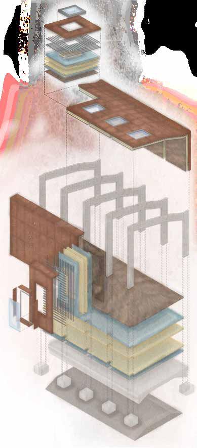
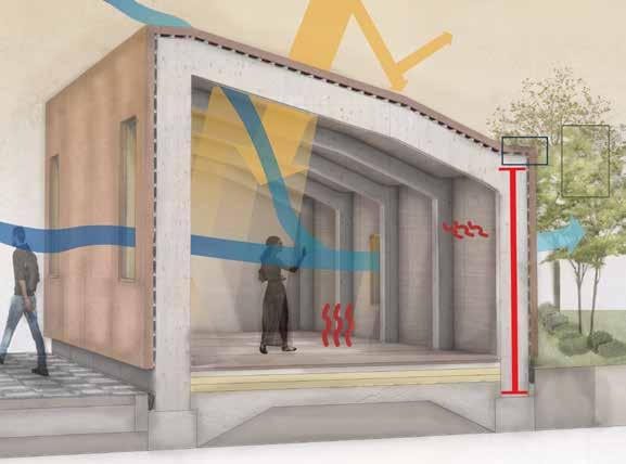
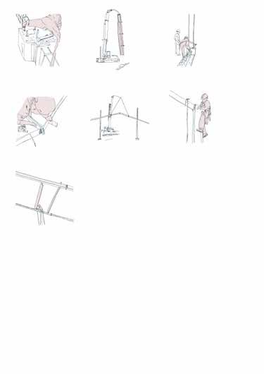
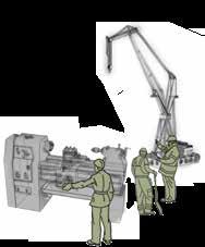
Passive Strategies for Ventilation and Lighting The Ventilation and Heating+Cooling Strategy: The ventilation strategy is composed of both passive and active systems working together so that the carbon emission is reduced. The active system used is the underfloor heating/cooling system. (underfloor heating and cooling system). The passive system is louvres built into the overhead skylight which promotes cross ventilation. The active system works by using the ground source heat pump converts the hearing and cooling of the earth below to feed the system with either hot or cold air. The system takes the hot or cold air into a hear transfer pump which heats/cools water to be pushed in the active underfloor heating or cooling pipes. This system is activated by temperature sensors in the interior environment. It can also be manually activated. Passive uses window apparatuses as well as the louvres in the intergrated window system (shown in diagram Tools section). This creates a passive cross ventilation system which is activated to open louvres when the humidity sensors note an increase in the room. The Lighting Strategy: Due to large apparatuses the design is mostly naturally light- resulting in a passive and low emitting system. Low wattage LED lighting is used to supplement this future at different times in the day. Due to the programme this may have to be altered in need of low soft light for interior comfort and programme specific needs- low glare and prevention of over exposure. This the factor is explored in testing page2. Solar radiation Water Converter Evacuated tubes storage tank Control panel PLC Thermal Thermal sensor ExpanPLANT ROOM Pump valve Multi pass underfloor arrangement Underfloor Heating +Cool System Ground Source Heat Pump System PLANT ROOM BUILDING Ground Source Heat Pump Heat transfer fluid pump Hot/cold water to heating and cooling system Convector heaters UnderFloor system WC Appliances Summer: warmed ground cooled water into the system Winter: cooled ground warm water into the system Structural Stystem The scheme has three main structural systems to cover the breadth of the programme throughout the site. The structural system focused in the fragment is the CLT portal frame system of the gallery space. Cross Laminated Timber Structure: The system explored uses a CLT portal frame which is mead out of 700x200x3000 mm columns and 700x200xlength mm beams/ rafters. There are 6 portal frames spaced evenly at 7m.These are the load bearing primary structure and the roof perlins and cross bracing of transom and mullions on both wall and roof are secondary. Load paths run across the roof perlins (2ndry) to the rafters and onto beams (1st) onwards down to the foundations to be dissipated into the ground. The foundation is a raft foundation to support the floor and wall build up between the portal frame. This is supplemented with PAD foundations in supporting the polar frames. Climate Change light environment for the programme which the building houses. Allowing a suitable light exposure for the programme- a gallery space, entail use of indirect light which lights the room well without glare and over exposure. Additional strategy for use of low operating artificial light will be needed for building optimisation throughout the day In order to test this, daylighting will be discussed through qualitative and quantitative testing of different location, size and pitch of the ceiling apparatuses. Additional test look into the method to prevent glare and over exposure such as window tint films and architectural devices (light shelves). In total these test allow results to show which way the building can most effectively utilise the natural daylight throughout the year. Cross Laminated Timber Life Cycle Reuse: As the CLT parts are standardised measurement for a portal frame, these can be disassembled and reused in full. This increases the life cycle of the parts. Recyclability: As shown above the parts can be recycled in many different ways. e.g. for smaller new parts of for energy or wood chips for further CLT production. This increases the life cycle of the CLT product. Energy: It is distrusted how carbon efficient it is to recycle CLT due to how carbon intensive the process is. With future improvements in this technology this will be more viable. Properties of Cross Laminated Timber An inherent advantage of CLT is its inherent fire resistance, designed to accommodate substantial fire damage whilst staying structurally stable. The CLT panels can remain fire resistant for up to 90 minutes. Desegregation rates vary due to the fire retardant protection added to the CLT. Other preventative methods include fire collars and stoppers. The fire proof material are used in the door stops and foundation prevent spread over the whole scheme through the habitable areas. Fire collars are used to accommodate services through the building and between different buildings in the whole scheme. The foundations are also succoured fully as shown in diagram (left) to be structurally adequate if fire/char occurs. meters Calculated effective depth of char d profile of effective residual section calculated notional char line profile of residual section profile of original section Loss of Section due to Charring TECHNOLOGIES POSITIONS Architectural Design Position + Technical Detail Study Purpose Retrofit: Within the schematic environmental strategy for both M+E and the climate emergency retrofit reduces embodied and operational carbon with use of existing buildings. Orientation: The orientation allows optimisation of the north light allowing the desired soft indirect light. This also prevent solar gain as the north light will be past 12:00 Flexibility of Space/Programme: Flexibility of space to be able to a flux in use of the building through lack of structural intermediate/portions thus increasing the lifetime of the building. Green Provision: To ensure the health of users through green provision and the breath-ability and environmental credentials of the build itself. Water Reclamation Strategy: a blue roof system is used to collect water at few downpipes for a cleaner aesthetic. Guttering is also at ground level on the south of the building. Standardisation of Construction Parts: To enable sourcing of parts instead of waste in offcuts from local suppliers standardised parts are used. This makes them more likely to be used in the future if disassembled. Architectural Design Position Technologies Response Building and Life Safety Process Technologies Response Life Safety Proportions Tools needed for the major construction of the building are distributed for 2 systems. The portal frame production and prefabricated build-up production/instillation. Cross Laminated Timber Structure: A CNC cutter is needed to bespoke cut each member of the portal frame. A CNC cutter is off site. On site this would be transported by crane to the site. This would not have to be a large crane as the parts are small. Prefabricated Buildup: All the build up would be assembled off site in units. These are standardised to the design and repeating. This would be transported to site and again installed by crane. Tools Technologies Artefacts CNC cross laminated timber machine Crane to install al, the prefabricated members Materials Technologies Artefact credit: Charlotte Bell 3.2 Studio Portfolio credit: Charlotte Bell 3.2 Studio Portfolio RIBA SUSTAINABLE OUTCOMES Technologies Artefacts Laying off pile foundations prior with holding bolt cast within. The bolts have to be loose enough to accommodate for 20mm margins. CLT columns are erected using a crane to hoist it into the HD bolts. Stability is ensured by tightening the HD bolts with a spanner. Safety checks ensure stability before removing crane hoist chains. The gable rafters are fit together by bolting before being hoist. This ensures strong joints which could not be done at height. Columns are well braced before hoisting the gable improving stability further. A crane is used to hoist each gable pair to column. Whilst still attached to the crane hoist chain either end of the CLT gable is bolted to the column. This is done simultaneously to ensure the correct placement. Next steps: The portal frame is assembled and therefore the wall buildup needed to be reacted. As shown below each portal frame bay has a prefabricated segment which is constructed off site. The crane hoists this to be installed via bolts (directly to the portal frame). This is for roofing and wall parts. The cladding is bolted on to transom and mullions. Prefabricated standardised window bays are added to finish the assembly. Portal frame perlins are bolted for cross bracing between the portal frame. This also improves stability further. Assets of the Construction Making it Accessible and Sustainable Locally Sourced Materials: Due to the close proximity of material sourcing the time and cost of transportations minimised. This means lags in constructibility are minimised to ensure quicker time-scales. Local Work Force: To aim for higher inclusion of the local work force of Preston’s local area, the method of construction are simple and un-specialised. This means there are low upkeep and workforce lags on construction, whilst suggesting a more sustainable economic workforce. Construction Process: With use of regular member sizes which are commonly used in construction the portal frame has a longer life span as can be reused in other projects. The CLT is not damaged when used in the building, showing low wear and tear. This is the assembly process of the portal frame (the disassembly process is reversed).
Diagramnumbers relevanttothe keyinthebottom left.
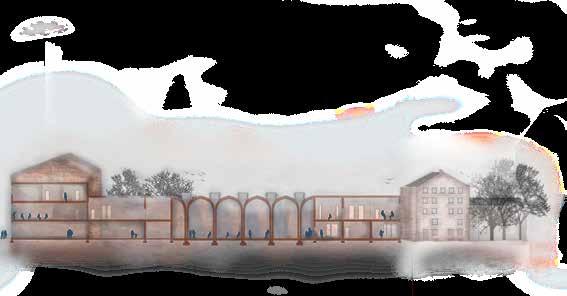
Sustainable Landuse and Ecology - “2.Priorities Building and Site Reuse” By use of two buildings within the existing site, the building deep retrofits the site. This is sustainable as economically retains building material which would have to be replaced, socially as retains known urban fabric and environmentally as reduces the embodied carbon emissions of the overall build. - “6. Create mixed use development with density appropriate to local context”. Justification through the site’s historical density (discussed in 3.1 Studio) creates way for increases in density drastically in the built intervention proposed. vad Co2 R E R C0 is found in high proportion in the airs atmosphere trees sequester carbon when they photosynthesise raw material (wood) is sustainably sourced and processed in a production plant cross laminated timber panels are made mass timber buildings store the carbon for their life cycle CLT construction components are manufactured from sheet recycling by dismantlement and rebuilding recycling recycling facilities CLT cut off Material Strategy and Credentials Locally sourced material is preferable to enable lower emissions associated with transport. Most produces are in a 200mile radius. Products include terracotta tile sourced from Darwen Terracotta, Blackburn based only 14 miles from site. The only material which is sourced out of the UK is the CLT which is most economically sourced in Denmark. 01 02 03 04 05 07 08 09 05 05 Schematic Climatic Emergency Strategy 02 03 04 05 01 06 07 08 09 The Position of Study Continuity’s Ethos: The stance of ‘retention’ and ‘reuse’ where possible is at therefore front of the ethos in which design is informed as a key driver by the design, architecture and site around it. Addressing the climate crisis in this way enables acknowledgement of: materials used (sourcing, production); processes for building operation; ecological stewardship over afterlife and the flux of use and residency in the building. Accumulating the layers of meaning and research from site, user and urban landscape creates rich design enabling socially, environmentally and economically sustainable design for the future. Project Aims: The aim of the design with the environmental ethos of CiA at the forefront of the design. The climate emergency is a key design driver of the design. Key parts of the aim include: keeping embodied and operational carbon at a minimal, by using material, processes and design curated to minimise emissions and enabling schemes for social responsibility of education to enable the low carbon initiative. In order to meet these aims, retrofit is combined within the site strategic plan; the design of the walls, floor ad roof build up is low omitting in both production, transportation and works within the environmental strategy to reduce omissions (i.e. thermal loss); passive systems will embedded to reduce the way in which the building runs for the future.
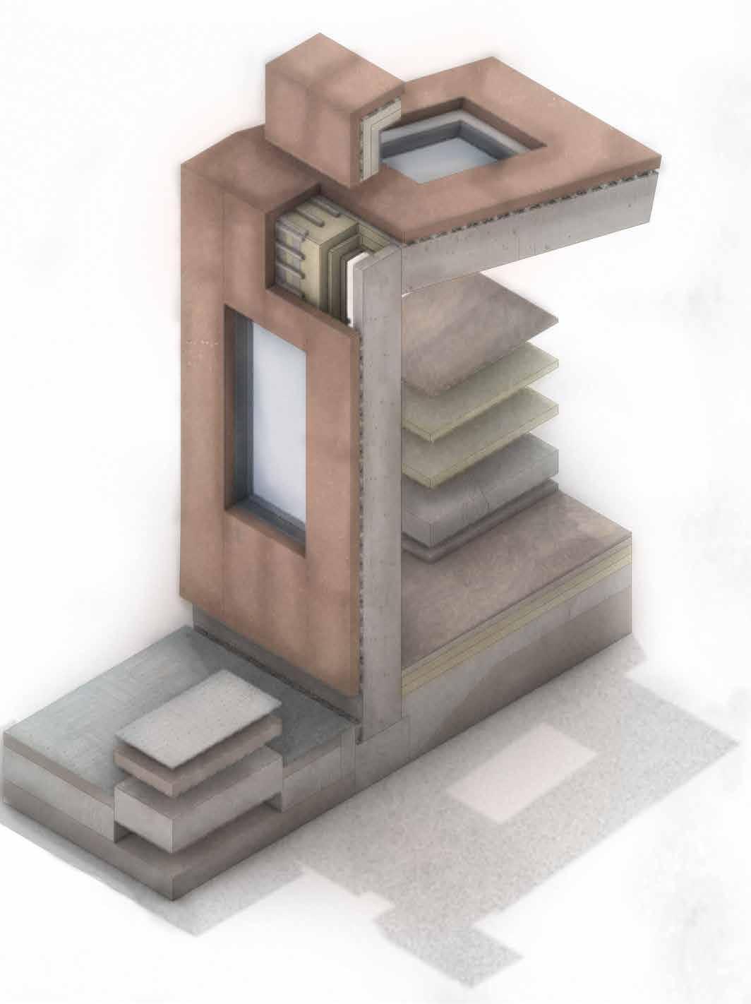
fulfil these aims creates a building which pursues a cleaner and environmentally conscience built environment working to catalyst this as a tend for Preston’s future built environment. Net Zero Operational Carbon - “3. Fine tune internal environment with efficient mechanical systems.” The efficient mechanical systems used are the ground source heat pump serving the underfloor heating and cooling system. This aids the passive cross ventilations and thermal masses. This system is effective as only heats the habitable 1.5m above floor level- thus not heating unused areas. LED artificial lighting is used due to its low wattage and energy usage. - “7. Prioritise maximising use of on site renewable appropriate to context” Use of PV panels on south elevations of the buildings harvesting enough energy to run a substantial part of the site. Net Zero Embodied Carbon Emissions - “8. Consider Modular OffSite Construction systems.” Modularise facade and structural systems enable all primary building components to be prefabricated and initial construction off site. As not all processes (in situ concrete pouring)cannot be standardised off site, the building can not claim Net Zero carbon. - “9. Detailing to be Long Life and Robust” Materials used (shown in Process section) have net zero carbon life cycles as can be reused and recycled in many ways. The longevity of each material is justified in the Materials section. Life Safety Considerations Fire Safety Collar deflectedframeshape originalframeshape R1 R1 c1 C2 Pinned base for structural stability in collapse Fire Safety Collar CLT wall for fire partition Collars fixed to either sides of the walls (standardised) to prevent the spread in either direction). Pipe housing the electrical/ other services made of ASTROFM compounds Column to Foundation Junction subsoil 400mm concrete slab 250mm concrete footing terracotta exterior tiles terracotta pannel cladding steel facade protector 600mm screed 500m PAD foundation + footing of portal frame 500m raft foundation WPM Floor and Wall Build Up indicated via diagram to the left. 700mm CLT Portal Fame column Steel Plate footing: - holding bolted 6mm - base plate 15m bedding space (screed) 50mm - steel screw in to anchor steel plates. Apex Junction 400mm terracotta pannel cladding 20mm roof perlins (dual acting as cladding attachment joints) 700mmm CLT portal frame beam steel bracket HD bolts Column to Beam Junction steel bracket connector HD bolts 400mm terracotta pannel cladding 20mm roof perlins (dual acting as cladding attachment joints) cladding attachment transom skylight double glazed with aluminium frame 400mm terracotta tiles 03 20mm roof perlins (dual acting as cladding attachment joints transom ) 04 20mm roof mullions 05 water proof membrane 06 2x 250mm firm insulation 07 vapour proof membrane 08 400mm terracotta tiles 09 20mm cladding attachment joints transom) water proof membrane 20mm roof mullions 2x 250mm firm insulation 13 vapour proof membrane 14 20mm inner plywood cladding 15 700x200x3000mm CLT Portal frame comprised of beams and columns 16 20mm double glazing 17 aluminium window fare and attachment 18 30mm window box and sill additional cladding pannel 19 20mm inner plywood cladding vapour proof membrane 2x 250mm firm insulation water proof membrane 23 500mm raft foundation 24 500m PAD foundation + footing of portal frame 24 500mm screed 26 100x300x30mm clay tile 27 arrogate sub soil 28 Screed with underfloor filament (heating/cooling) 03 04 05 06 07 01-07 in modular system 09 10 08 13 14 01 15 16 17 18 19 23 24 25 08-18 in modular system Recycling and Reuse: A lot of the site is retrofitted and therefore material is not removed-however, some areas of the Lancaster Rd. terrace is remodelled. When available these materials can be given a recycled purpose for non structural and decorative purposes. This allows low waste and less need for production of new materials. Material: Plywood Board Role/Placement: Interior cladding Longevity: 20-50 years Fracture Reason: Wear and tear Material: Terracotta Cladding Role/Placement: Exterior Cladding Longevity: 100+ years Fracture Reason: water damage in non glazed tile SITE miles 200 miles EU Insulation producers cladding producers CLT producers exterior tile producers timber supplier concrete producers Material: Concrete Role/Placement: Foundations Longevity: 100+ years Fracture Reason: Time, stress, increase/ change in load Material: Clay Glazed Tile Role/Placement: Exterior Tile Longevity: 30 years Fracture Reason: Rot or woodwork/ weathering (mechanical) Material: CLT Role/Placement: Structure Longevity: 60 years Fracture Reason: Stress, De-lamination, Change/Increase in load. bioenergy further CLT production 200x200mm concrete support aluminium frame and sill 20 mm double glazing mechanical system for operable windows operable louvre system general wall/roof build up below Operable Louvres/Glazing A mechanical tool within the building for thermal/ lifting comfort is the operable meantime associated with the glazing and louvres (ref. Climate Change Section). 28 between 19-20 Underfloor heating and cooling within arrogate screed layer 250mm
To
development of the southern elevation fenestration could help to prevent these points.
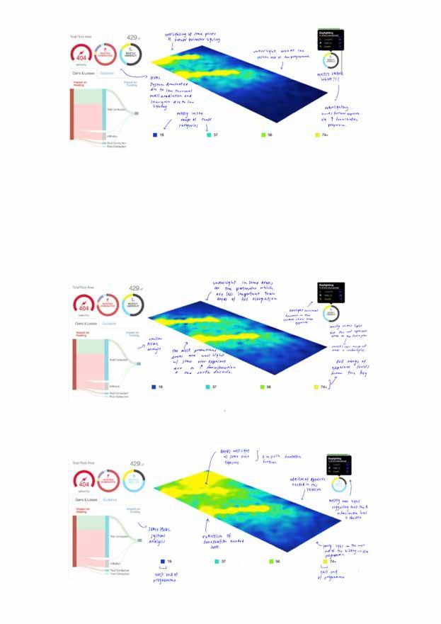
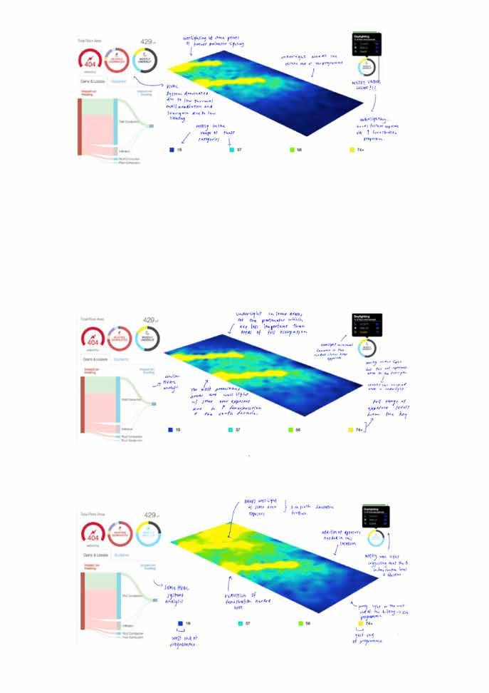

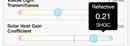
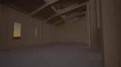
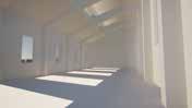
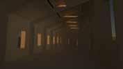
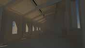
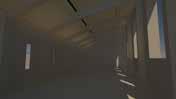


Charlotte Bell BA3 Technologies Part C: Technical Detail Study: “Responsible Buildings” 08 PROTOTYPING Iterative Testing | Record of Process Wall U=1/ cladding+2(insulation)+plywood+RSI+RS0 =1/0.85+2(40)+0.14+0.12+0.06 =1/81.17 0.012 W/m K (2dp) Passive Haus approved (0.010.15 W/m3K) Roof U=1/ cladding+2(insulation)+plywood+RSI+RS0 =1/0.85+2(40)+0.14+0.10+0.04 =1/81.13 0.012 W/m K (2dp) Passive Haus approved (0.010.15 W/m3K) Floor U=1/ plywood+2(insulation)+concrete slab+RSI+RS0 =1/0.14+2(25)+1.40+0.14+0.04 =1/53.12 0.018 W/m K (2dp) Passive Haus approved (0.010.15 W/m3K) WL2=(9.65KN/m)x(8)2=617.6KNm Required Moment Length (Mpl) Adequate Section Size table used to substantiate (with plastic modulus on table> plastic modulus calculated) Rafter: 171x51cm Column: 191x82cm Energy Efficiency of the Building Materials- U values (U=1/R1) Comparison of Insulation Materials on the U-Value/Energy Efficiency Window Film to Prevent Glare The reflective/dark window film is a static clinging material designed to control reducing excess heat, UV light and glare into the interior space. This is useful in the design as for the programme (gallery) glare and over underexposure to be kept low in order to keep an comfortable interns inversion as well as prevent damaging the art work. It can be seen the glazing at 0.21SHGC is reflective. Measures to Create a Conferable Interior Environment (Thermal/Lighting) Advantages: - The R Value is higher (than cellulose/fibreglass), better resisting heat flow in to outside - Naturally sourced material w/ low embodied carbon - Less material required due to higher R Value -Non-flammable material Disadvantages: - vulnerable to insects w/ alternative of polluting insect resistant chemicals Advantages: - Air-tight seal is created preventing heat loss and moisture accumulation from condensation - The R Value is higher than all other materials better re-sighting heat flow in to outside Disadvantages: - Sophisticated equipment used with high pressure and heat. Expensive and specialist operator needed. Open cell spray has to be used to ensure the high R Values - Can lead to mould and termite damage - Toxic when improper chemical ratios mixed. CONCLUSION As Sheep Wool Insulation has greater insulating credentials than most other alternatives as well as other credits concerning the climate emergency, this insulation will be used. This is also far more accessible for insulation by the desired workforce. Type02-Sheep Wool Insulation (2x25cm) Type01-Spray Insulation (2x40cm) CONCLUSION The film creates the desired effect (as shown in industry standard testing (diagram above) and in the rendering testing (showing lower exposure with the film) this will be taken forwards as a control variable in all iterative testing. A bonus of the film is the solar gain prevention in transmission (only with a 12% post film). Iterative Testing for Factors Exploded in Climate Change PG01 Alternate Climate Testing- Thermal Efficiency of Proposal R Values= 7/inch R Values= 3.8/inch Alternate Climate Testing- Window Film on the Proposal Constructibility Reflections on Pre Fabrication Further Explored As the sky lighting system is modularised it can be produced off site prefabricated and delivered to site. This will reduce cost time and quality among other benefits of prefabrication. As the materials are the same as the other defined prefabricated systems this will be another component added to a manufacturing system at a factory. Without Solar Film This test shows over exposure of the room as well as glare. This is evident from the lack of clarity in the image due to over stimulation of the direct solar transmission With Solar Film Due to the film, there is less transmission of the direct solar rays. This allows a less exposed (with less glare due to reduce UV rays) which is more appropriate for the gallery programme. complex roofing system with new beam pre fabricated off site due to specialist reflective metal sheet, the light shelf is also prefabricated off site to be constructed/joined on site light shelf screwed into the portal frame in a simple joint the fragments of prefabricated panels join to the sky light piece through seam less welding and joints of insulation and WPM/VPM panels of glass are not prefabricated into the skylight as have potential for shattering. Glazing is fitted at last stage of construction of the portal frame system. What is the Change (independent variable)? The factor tested here is change in pitch of skylight orientation. This is by optimising the north light by adding a skylight box (instead of the skylight following the roof line). The skylight faces north perpendicular to the ground. The Desired Effect Indirect soft light from the north which will light the room well at a more appropriate angel. North Light Window Box By adding a skylight at a north angel this creates indirect light as is not directly from the sun therefore is at a consistent angel and colour throughout the day, with no sharp sun exposure points or shadows. 09:00 The lighting dull and under exposed, however is harsh with sharp shadows and light spurs. Qualitative Light Testing- Rendering Summer Solstice July 23 Winter Solstice Dec. 23rd 12:00 Due to the small skylight aperture size, at mid day this is not sufficient in lighting the interior as there is intimal lighting. The perimeter glazing do not create much daylighting into the interior 15:00 The daylight is underexposed and has no light spurs therefore the interior is unusable as would be hard to navigate. Artificial lighting would have to supplement. Record of Process Iterative Test 01- Creating North Light Qualitative Light Testing- Rendering Iterative Test 02- Optimising the North Light 09:00 As this is winter solstice it can be assumed at early/late hours there is low lighting/exposure. Artificial light would be needed to supplement. 12:00 There is extremely low exposure- to the extent that the skylight aperture and perimeter apparatuses are making little to no difference in use of solely daylighting. 15:00 There are some light spurs however, this situation would have to be supplemented with artificial lifting. 09:00 There are harsh shadows and light spurs from the south light in the morning. This is a little over exposed and could cause glare. Summer Solstice July 23 Winter Solstice Dec. 23 Due to the small aperture size of the skylight, there is ineffective lighting of the room. The perimeter apparatuses create harsh lighting (as are not indirect north lighting). This creates an interior which at all points of the year would have to be supplemented by artificial lighting due to evident under ex posure and UV transmissions. Iterative Test 03- Well Light Spaces Using A Light Shelf CONCLUSION It can be concluded that the light self helps to distribute the indirect north light effectively around the interior creating a softer and evenly exposed interior environment. The optimal lifting is found at 15:00 on summer solstice and 12:00 at winter solstice. This can be expected as this is when the north elevation will be in sunlight. To prevent over exposure light spur points,
Performance Criteria- the aims for testing What am Testing? The fragment is being tested mainly against how effective the lighting system is concerning different variables. The changes range from angel, size and pitch of aperture. Other features are acknowledged in this testing such as: need to prevent solar gain; material’s reflectivity and thermal mass ability. There areas are tested before the main iterative testing to be control variables. Control Variables- the space (the fragment), times of day tested; the intensity of sunlight, opacity of window film. Independent Variables Itteration01- change in pitch of skylight orientation Itteration02- change in size of skylight aperture Itteration3- addition of light redirecting device (light shelf) The Existing Environmental Strategy 01 Direct Light in the skylight all day- this could cause issue of overheating/lifting which is not desired in the programme (gallery) as would cause glare 02 Light Reflection Due to the reflective nature of the glazed terracotta cladding, the light will reflect off away from the building. This helps a smaller amount of direct sunlight enter the apparatuses. 03 Re-Radiation Less thermal energy enters the interior energy through the apertures due to the double glazing which acts as a thermal barrier. This is desired as in summer this could overheat the area. 04 Ventilation Louvres When air rises change in pressures inside and outside (pressure gradient) will make the air move out of the louvres. 05 Thermal Mass and Heat Release The inner lining of the building is plywood, thus a high thermal mass. Wood has the ability to absorb and store thermal energy in the day and will recommit this same thermal energy at night- i.e. when the re radiation heating is low (no sunlight). 01 03 04 07 100% SUN ENERGY 45% solar energy reflected 32% absorbed solar energy(outside) 77% TOTAL SOLAR ENERGY REJECTED 11% Direct Solar Transmission 12% absorbed solar energy(inside) 27% TOTAL SOLAR ENERGY TRANSMISSION g value:0.23 3mm CLEAR GLASS + R20 SRCDF FILM Solar Film DIAGRAM TO SHOW THE CHANGE IN THE FRAGMENT AND THE DESIRED EFFECT OF THE TEST reflected light off the terracotta and film due to the angel hitting the terracotta before the glazing light into the space at a low angel therefore the light is at higher exposure above the users habitable space What is the Change (independent variable)? The factor tested here is changing the size of the skylight to allow a larger aperture and glazed area. This also impacts the pitch as the pitch has to be more obtuse to accommodate the larger glazed area. The glazed area remains perpendicular to the ground and at a north orientation. The Desired Effect Maintaining the effects found of the light quality interns of an indirect soft light from the north however, creating a more exposed light to fill the room further with light (to prevent need for much artificial lighting). before- the light will enter the interior at any angel- over exposure of light after (desired)- the light enters the interior at a low pitched angel which can be more easily design to dissipate effectively 120 the angel of light remains mostly the same allowing similar lighting effects (i.e. soft light) singular angel of light (due to aperture location) at a low angel= above habitable area = reduced glare 140 DIAGRAM TO SHOW THE CHANGE IN THE FRAGMENT AND THE DESIRED EFFECT OF THE TEST further amount of UV/ glare reflected as the glazed area is larger. The excess removed controls the negative externalities of light further. light into the space at a low angel therefore the light is at higher exposure above the users habitable space pitch change of skylight box allowing a larger galzed area What is the Change (independent variable)? The factor tested is implementing a light shelf into the design. The other factors changed up to this point (in itteration01/02 remain the same and become control factors in testing). The glazed area remains perpendicular to the ground and at a north orientation. The Desired Effect In use of the light shelf theory suggests with a reflective material, the sunlight should enter the glazing, reflect of the light shelf and the light enters the space. Due to these reflections, the light reduces in UV and glare, producing a less overexposed areas. additional artificial lights light reflected off wall/ light shelf enters the habitable space at a low UV exposure 100% UV Exposure 70% 50% 30% 100% UV Exposure 70% 50% 30% 30% UV exposure reflected off the glazing film and cladding=less exposure enter the interior space light entering the space is at a low enough UV exposure that the angel is not a determining factor Original Fragment Anatomy 02 03 03 03 04 05 05 10 06 07 08 09/ 13 14 01 01 02 02 02 04 Changes carried forward into the next Iterations 04 Change to detail: the system becomes smaller and more compacted at a slightly smaller capacity 11 Change to 1 sheet of 250m sheep wool insulation in the skylight box due to accommodations of a thinner roofing system. 15 The addition of an beam which runs at the base and header of the skylight for an extra support. The beam is CLT. The beam is filled with 100mm insulation to keep a continuity in the insulation system. 04 04 05 05 05 05 05 05 01 double 3mm laminated sheet of glazing 02 aluminium window frame and sill joint 03 reinforced concrete furring and headings 04 mechanical louvres system 05 aluminium steel joining plates with steel bolts 06 400mm terracotta tile cladding 07 water proof membrane 0820mm cladding attachment (dual use roof perlins) 09 20mm roof mullions 10 mechanical louvre system 2x 250mm sheep wool Insulation vapour proof membrane 13 20mm inner plywood cladding 14 700x200x3000mm CLT Portal frame comprised of beams and columns KEY USED THROUGHOUT PG2 DETAILS 06 06 06 07 08/09 10 07 08/09 12 07 08/09 13 13 13 15 15 15 16 Changes carried forward into the next Iteration 16 The addition of the light shelf. A 200mm sheet of plywood lined with a 100mm reflective copper. This is suspended from the CLT portal frame beams using a metal cord and securing hooks. 09:00 As this is winter solstice it can be assumed at early/late hours there is low lighting/exposure. Artificial light would be needed to supplement. More of the space is well light, however, there is now an overexposure problem as there is too many perimeter apparatuses in the room. This indicates that there is south lighting predominately over the desired north lighting. This results in an uncomfortable internal Refinement of the facade fenestration pattern/size to prevent over exposure in south lighting. Further prevention of over lighting (e.g. light shelf). 01 10mmm steel plate to separate the beam to column 04 10mm steel panel joins the two bowdalled plates together between the M25 bolts and the CLT. 02 20mm bowdalled steel plates bolted connections to the CLT portal frame 03 M25 Bolts are used in a linear formation to join the recessed plate to the CLT. 05 Steal hollowed haunch at the size specified in the calculations (left) 06 D30 bolts join the steel to the CLT. 07 30mm CLT sheet to encased the joints. 08 CLT portal frame Column to Beam Junction 01 02 03 04 05 07 06 08 CONCLUSION It can e shown that most of the space is light well at 52%. The areas which are under light (24%) can be used for ancillary spaces. The over lighting can be further iterated in the south facade to create a well light and prevent over exposure. This can be done by further reducing size of apparatuses on the south facade to prevent southern lighting. DIAGRAM TO SHOW THE CHANGE IN THE FRAGMENT AND THE DESIRED EFFECT OF THE TEST
Reflection on the Technologies Positions and Design Insights
Key Features Explored within the Fragment Details?
The key features of the fragment and technical detail explored is systems of the skylight glazing and the mechanical louvres as well as the structural strategy of the cross laminated timber portal frame system. The Systems and How they Relate to the Technological Aspects? How the Systems have been Tested (Pg02) and further progression?
01) The skylight is a fixed glazing system which has been design to support north indirect lighting of the interior space. The skylight also includes a lighting shelf, suspended upon the CLT portal frame beams with tension cables and eye hole hooks. The system helps to provide a comfortable interior environment by demising the UV light rays intensity and reducing glare into the habitable space of the interior.
The skylight responds to climate change by addressing how the environmental strategy can be stretch further in creating a net zero system via use of natural daylighting instead of carbon intensive artificial lighting systems. Building and Life Safety is addressed by further additions to the structural system to cope with the addition of loads put upon. Constructibility is considered by comprising on further prefabrication of the system by creating standardised modular units which slot into one another and the CLT portal frame structure. This enables high quality, quicker and easier construction, that would hopefully be more cost efficient.
The system has been tested to establish the way the glazing could light the space to be appropriate for the programme. The desired effect is indirect, soft lighting. This was tested by changing the pitch of glazing, size and then testing different lighting features. This was effective in establishing if the desired conditions are met in each iteration as these are substantial changes. It was concluded that the larger window tested was the most effective in con-
junction to a light shelf. This was most effective as allowed apple light into the interior, however with the light shelf device, the light was dispensed into softer indirect light as desired. As further improvements and iterative testing, looking into the size and materiality of the light shelf could help to further evaluate the effectiveness at all times of day. Looking into the re tractability of the device could also allow lighting further in the morning and evenings with the natural daylight.
02) The CLT structural portal frame strategy is designed to create a large column free interior which celebrates the structure openly and exposed on the interior. The portal frame structure consists of six portal frames which use both acute and obtuse angels to create a downwards pitching roof. Cross bracing additions are fitted in the final two bays to establish stability against lateral load. The system provides a stable structural basis for the modular wall build ups to be attached to.
The structural system responds to climate change as is using renewable material sources (CLT)with full life cycle analysis, meaning that the environmental impacts are minimised. Building and life safety is addressed by ensuring structural stability in the system by ensuring each parts stability via calculation as well as understanding construction practice in terms of fire safety in case of collapse. Constructibility is made to ensure easy erection with few specifiably processes. The parts are standardised and accessible. The system is tested to establish the stability. This was tested by calculating the plastic modulus and adequate section size for each column and beam. This established changes in dimensions to the portal frames and its elements. In addition to this, calculations showed which additional secondary structure is needed and where they would be needed. Testing showed that the structural system is adequate with addition of bracing on the middle and end bays. Looking into further tests, prototyping and loading the structure (or simulation) could help to see if breaks or buckling would occur.
20 Copper concealed guttering. Junction between two cladding tiles, leading to a blue roof system down pipe at the north, east façades.
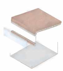
21 Roof perlins cladding attachments. The terracotta tile has a projection which locks directly into the shape of the perlins as a ‘lock and key’ mechanism.
22 Shadow gap terracotta tile junction. Overlapping cladding segments connect in
‘z’ junction. The small gap at wither side of the cladding junction is filled with a copper T shape stopper to ensure waterproofing of the system.
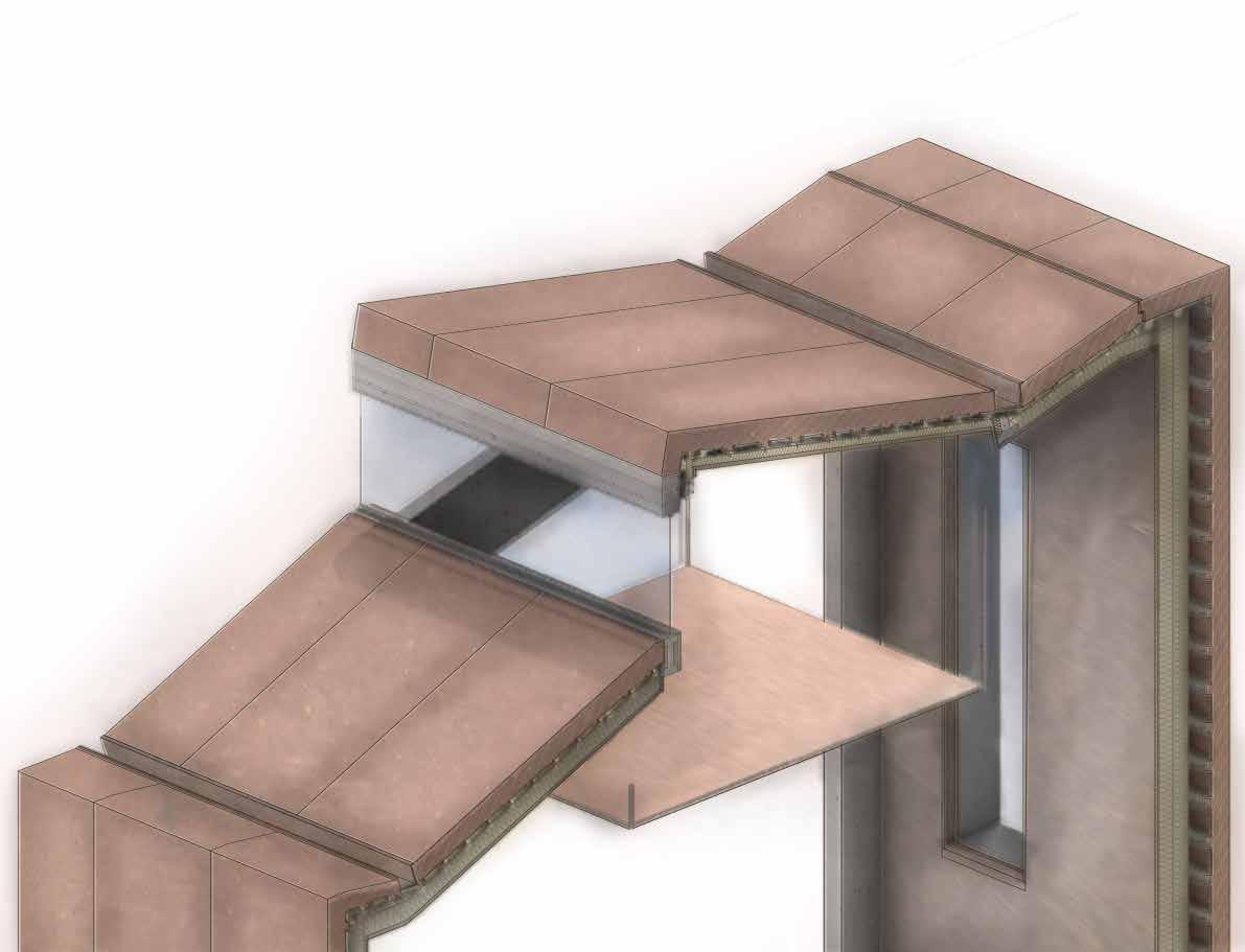
Charlotte Bell BA3 Technologies Part C: Technical Detail Study: “Responsible Buildings” DETAIL 02 DETAIL 03 DETAIL 04 DETAIL 05 01 double 3mm laminated sheet of glazing 02 aluminium window frame and sill joint 03 reinforced concrete forcing and headings 04 mechanical louvres system 05 aluminium steel joining plates with steel bolts 06 400mm terracotta tile cladding 07 water proof membrane 0820mm cladding attachment (dual use roof perlins) 09 20mm roof mullions 10 mechanical louvre system 11 2x 250mm sheep wool Insulation 12 vapour proof membrane 13 20mm inner plywood cladding 14 700x200x3000mm CLT Portal frame comprised of beams and columns 15 Beam supports for window light 16 Tension Cable 17 Eye hole hook 4’’ shank (joins to the CLT portal frame and the plywood light shelf) 18 Copper Reflective Film 19 Plywood Light Shelf
Integrative
| Design
01 02 04 05 05 06 12 07 08/09 11 13 15 16 Skylight Detail- 1:5 @a3 17 18 19
TECHNICAL DETAIL
Systems
Conclusions
a
23 151x10mm Copper T shape joint filler lined with free foam for stability/waterproofing properties 24 Interior window sill 20mm plywood 25 Exterior window sill 20mm terracotta tile cast shape to prevent water stagnation Skylight Detail Axonometric Detail- 1:5 @a3 01 02 05 04 15 24 25 DETAIL 03 Roofing Guttering Axonometric Detail- 1:5 @a3 20 21 DETAIL 02 Joint between different Terracotta Cladding Tiles Axonometric Detail- 1:5 @a3 20 06 11 07 12 13 22 23 DETAIL 04 Terracotta Cladding Tile Junction and Mullion Attachment Junction Axonometric Detail- 1:5 @a3 20 06 11 07 12 13 DETAIL 05
