Brian Zhao
UCL MArch Portfolio
Email: bz755822@gmail.com
Contents
A Heritage of Movement
Page 3
Technical Studies: Fabric Formworks and Mycellium
Page 5
NEST Page 6
Temple Bar Gate Waltz Page 8
DLAB Workshop
Page 10
Beyond Isolation Competition
Page 11
Models
Page 12
Warren and Mahoney Internship
Page 13
ADAM Architecture Part 1 Experience
Page 14
Miscellaneous Page 18
A speculative heritage project for the post-industrial city of Trieste
Experimenting on spent coffee-mycelium with fabric formwork.
Work experience on a bridge project.
A latex cast of a Grade 1 heritage building
Computational design and digital fabrication of a plywood seating area
A proposal for inhabiting the niches of Barbican Station
An underground cultural hub for a First Year competition at the AA
Collage and Mappings of New Zealand
Model Making Process
Visual Arts: Sculpture, Drawing, and Painting
2
A Heritage of Movement
The proposal emerges from a response to the restoration of the post-industrial port of Trieste. The intervention looks at taking a decommissioned pontoon crane, an artifact of archaeological industry, and recommissioning it as a moving filter using a coffee composite material.
Inspired by properties of a novel sponge composite made of coffee waste which can filter heavy metal residues, documented by Italian researchers.

The buildings highlighted in red are places of industry. Red fills are sources of spent coffee grounds (SCG) and red fills with white hatches are ports which harbor larger contents of metal residue.

The dotted line with white lines offset is the main path of the floating crane as it travels along the coast. The dotted white lines diverging are detours to mooring areas. The dotted black lines are local ferry routes.

The spaces filled in a dark red are mooring points, this is where the pontoon crane would moor in-between the completion of its journey.

49.8 0 meters above sea level 3 meters above sea level 5 meters above sea level 1.5 meters below sea level 21.5 meters below sea level 23.5 meters below sea level 26.7 meters below sea level 28 meters above sea level 28.3 meters above sea level 32.3 meters above sea level 52.3 meters above sea level 55.5 meters above sea level 67.5 meters above sea level Plan and Front Elevation of Proposed Ursus Scale 1:200
Fig. 1 Mapping of program and site Fig. 2 Exploded axonometric of Ursus at its docking point in the old port.
Fig. 1
Fig. 2
1911
1931
Section of Ursus with exploded plan of addition and technical diagrams
4 The organic shape of the coffee and mycelium mixture would be cladded on top by a series of separate cured mycelium that would allow for some movement. The elements would be prefabricated, first to calculate their geometry whilst unwrapped digitally and then to use the spent coffee grounds and mycelium to grow the material The underside of the bag has perforations that allow water to pass through and for heavy metal residue to be adsorbed by the coffee mycelium inside Section AA’ Section BB’ B series of air lift bags would be used in conjuncton to keep the additions buoyant. is also able to sink the bags to create weight while anchored 2 3 4 2 3 4 Ursus Section Scale 1:200 Air can be regulated by valve When the airlift loses air and buoyancy it then sinks and will lower the other elements of the joint composites. Underwater Air Lift Mechanism Engine Room Machinery Operating Booth Loss of Air and Buoyancy Addition in Plan Scale 1:200 Single Cell Machinery
Fig. 3 Fig. 4
Exploded axonometric of Ursus at its docking point in the old port.
Fig. 3 Fig. 4
added
WWII
Ursus
to work cleaning
coast.
in the present the Ursus takes up a new role clearing the coast once more
a crane was
after
and the
set
and repairing the
Building along the coast and creating breakwaters NOW
solely for storage URSUS
the Ursus was built as a ship
Technical Studies: Fabric Formworks and Mycellium
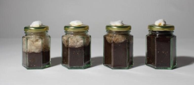
Developing a building system for my restoration project I experimented with fabric formworks and mycelium grown from coffee grounds. Utilizing material otherwise discarded to generate new insulative building material, the formwork molds the shape of the mycelium and helps securely incubate the mycelium in its growth.

Mycelium suits insulative material and when treated can have hydrophobic properties, as such these elements could be pregrown to cover and guard the steel of the Ursus from the natural elements of wind and water whilst creating new habitable spaces.



5
Fig. 5
Fig. 6 Plaster casts as mockup for mycelium fabric formwork Test using spent coffee grounds and pink oyster spawn, sealed in heat-sealed HDPE bags
Top View Contour Drawing 5mm every contour line
Formwork Section AA’
Fig. 6
70cm
A A’
100cm
Top View Contour Drawing 5mm every contour line
Fig. 5
NEST
Work from 2021-2022
Using the word ‘Half’ as a guide throughout the year, this second year project explores what the notion of half might be.
Through the survey of ‘nests’ or ‘niches’ in the interiors and exteriors of London, proposals on how we might deal with these recesses of the city reveal more of what ‘Half’ might be. This project ends with designs for the inhabitation of the recessed blind arches within Barbican Station. Becoming capsule hotels for travelers.
7 Fig.8 Fig. 9
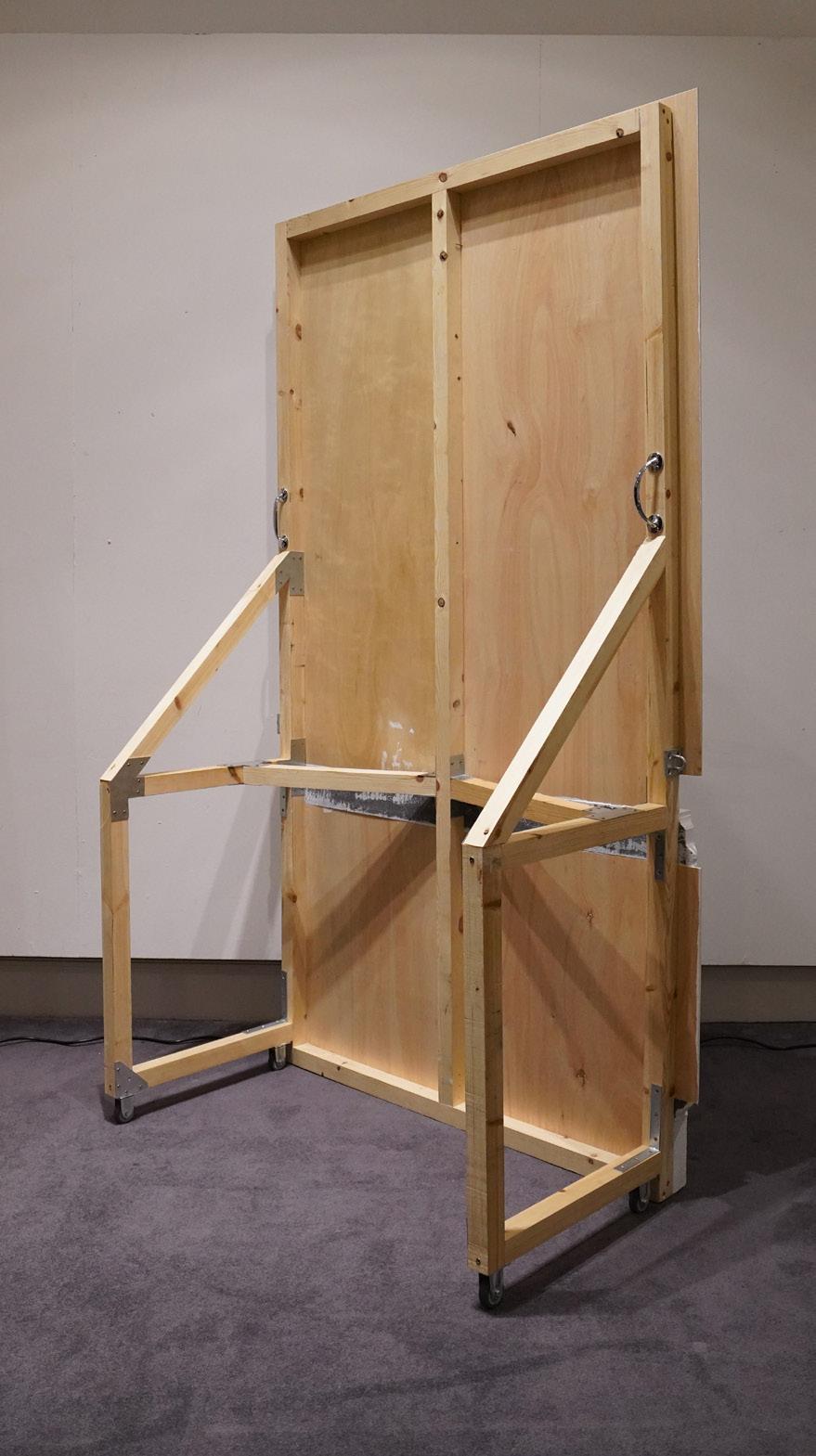
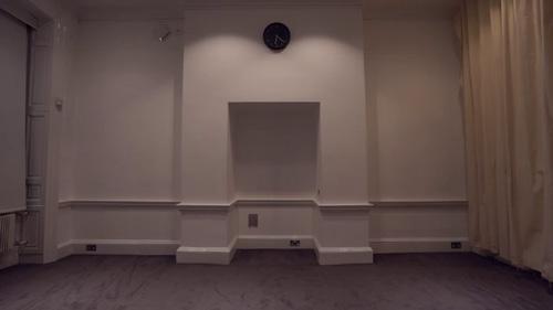
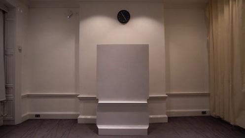
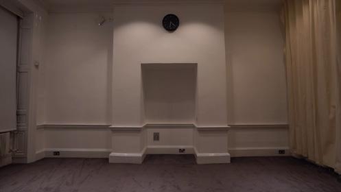
Technical drawings and Axonometric of site, or niche, for installation within the chosen room.
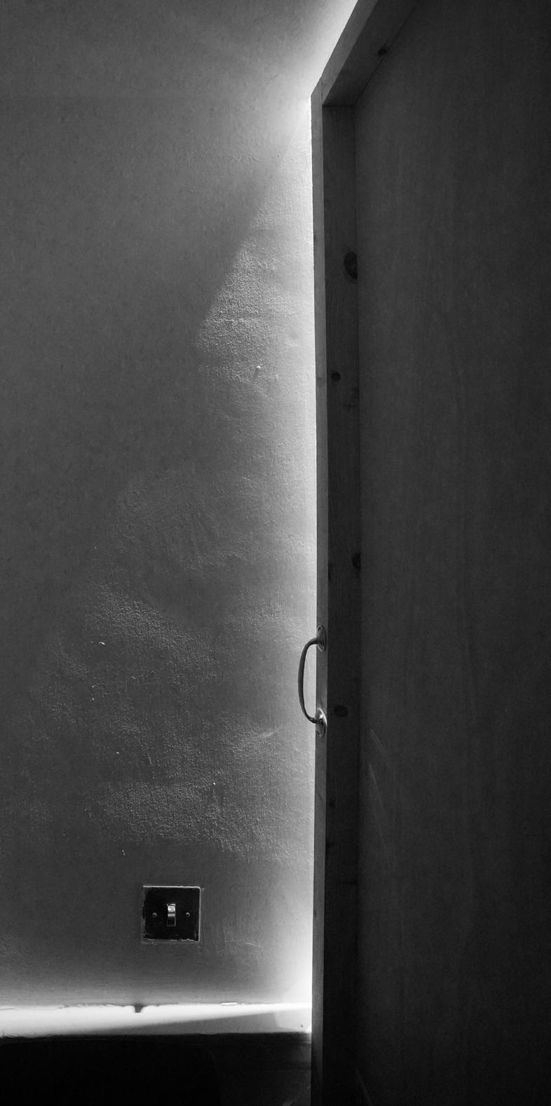
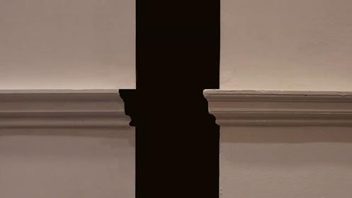
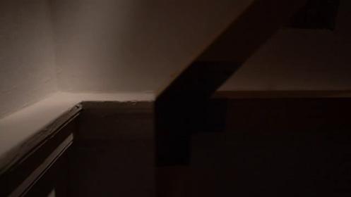
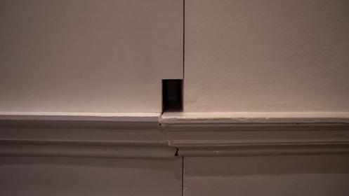
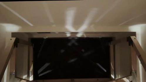
Photography of the model from the exterior and from interior of model docked in site exploring how it may be used.
FIg. 7

Fig. 8





6 50 50 620 1608 1292 1608 246 1300 1250 1150 1150 1150 746 746 Perspective Section Scale 1:20 Moulding Profiles Scale 1:20 Perspective Elevation Scale 1:10 Plan Diagram 50 149 50 1110 1320 10 530 20 620 1608 1292 1608 246 1300 1150 746 746 Perspective Section Scale 1:20 0 : 0 0 0 : 0 7 0 : 1 6 0 : 2 5 0 : 3 0 0 : 3 5 0 : 3 8 0 : 5 0 1 : 0 0 1 : 1 5
Fig.
Stills from a short film involving the model https://vimeo.com/825695156?share=copy Fig. 9


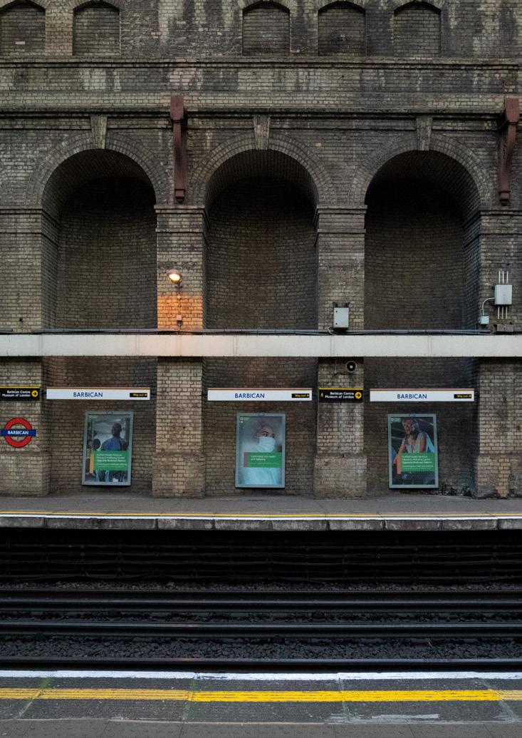

 Fig. 12 Sequence of collages illustrating phases of cleaning the station niches and their filling
Fig. 10
Fig. 11
Technical drawings of proposed inhabitation with external view, internal view. As well as station plan + different plans at different heights + Axonometric of proposal
Coloured Plaster Site Model with 3D-Printed Proposal showing the space within and the stairs to traverse the levels inside the nest.
Fig. 10
Fig. 12
3.5m 1.5m Section BB' Internal View Section AA' Height 1m Height 5.5m Height 3.5m B' A External Front Elevation 5.5m Height 1m Height 3.5m Height 5.5m Plans of proposal Scale 1:50 on A2 Section BB’ Scale 1:50 on A2 Internal View Section AA’ Scale 1:50 on A2 Station Level Plan Scale 1:250 on A2
Fig. 11 Original
Proposed Halfway
Temple Bar Gate Waltz
Work from 2022-2023
For a project we surveyed a British Heritage building within the M25. For our site we chose the Temple Bar Gate (Grade 1 Heritage building), opposite the Paternoster Square. Starting the survey we decided to investigate the building in terms of joinery, a building as a series of assembled parts. As well as the joinery, the historical, and social aspects of a heritage building. This ended with a latex cast capturing the different changes made to the bar gate.
Fig. 13
Fig. 14
Fig. 15
Timeline of Temple Bar’s modifications and history
Mapping of Temple Bar’s movements
Drawings of Temple Bar versions through history


Hertfordshire
The Meux estate in Hertfordshire was passed to Lambton, who then sold it later on.

Valerie
A


Fleet Street


Isle of Dorset
Portland Stone comes from a quarry in Dorset, delivered by sea into central London
Italy
The Temple Bar bears elements of the baroque aesthetic
8
Paternoster Square
Fig. 15
Portland Stone Temple Bar Gate 1672 Onwards Wooden Temple Bar Gate 1327 to 1672 Chain Temple Bar Gate Before 1327
Paternoster Square 2004 In recent times the Temple Bar Gate was secured by the Temple Bar Trust in 1984, and then brought back to central London in its current residence at Paternoster Square. Near some of Wren’s other designs. Hertfordshire Temple Bar Gate 1880 Wooden Temple Bar Gate 1327 After the Great London FIre of 1666 it was decided the Bar Gate would be remade in stone. Many designs were proposed but ultimately it was Christopher Wren who won the bid. Though there is still some questioning towards the legitimacy of this claim. Other Gateways Demolished 1760’s Christopher Wren’s Portland Stone Gate 1672 Sold by Lambton 1938 Bar Gate Disassembled and Temple Bar Gate Memorial 1878 The Bar Gate was deconstructed and left in a yard along Farringdon Road, it was then saved by Valerie Meux who persuaded her husband Henry to purchase it for her and it was installed in their Hertfordshire estate.
Fig. 13
and Henry Meux
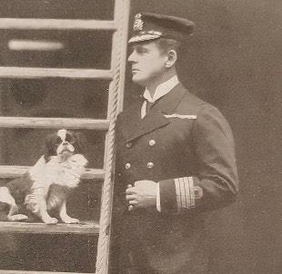
pair of socialites who married in 1878. Valerie married into the Meuxs - one of Britain’s largest brewing dynasties. Hedworth Lambton Lambton was a navy officer who impressed Valerie when they had met - Valerie later passed on the Meux inheritance including the Temple Bar Gate H.W. V.M. H.M. Christopher Wren Famous English Architect who was quite active around the Great London Fire. Known for his English Baroque style and use of Portland Stone
Fig. 14
Fig. 16
Fig. 17
Fig. 18
Final Latex Cast
Proposed site for latex cast
Cast Collaged History and Parts

New Brick 2004
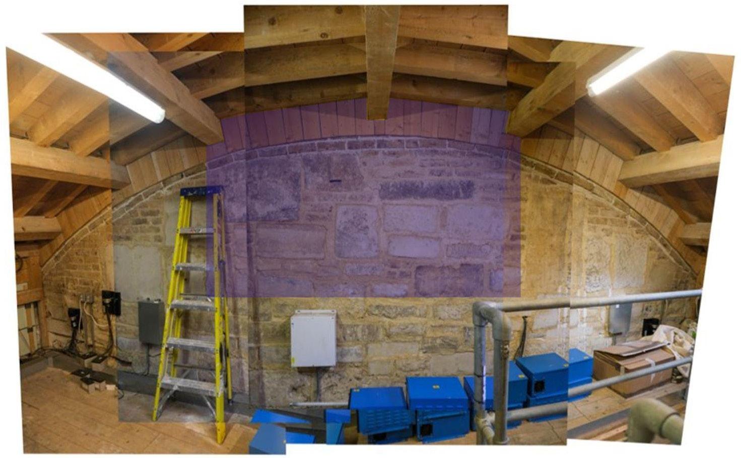
New additions to the Temple Bar to fit its new site.
Older Bricks 2023
Bricks from Hertfordshire
Because of a hole, a flap is extruded outwards at this part, this would’ve been an incision made in ithe original stone for a crane to be used to lift the stone.
Lime Mortar 2004
Lime Mortar newly added as the latest binder used in the Temple Bar Gate.
Tape 2023
Leftovers from the latex cast left behind on the cast

Portland Stone 1672
The original stone from Christopher Wren’s version of the Temple Bar Gate.
Markings
1672-1880
Inscriptions from the original construction as well as remnants of graffiti from Hertfordshire
9
Fig. 16
Incision 2004
Fig. 17
Fig. 18
DLAB Workshop
Work from 2022-2023
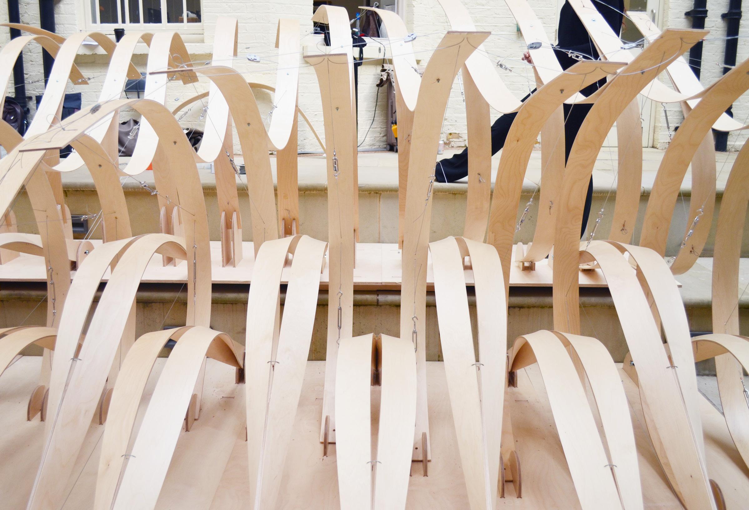
Exploring computational design and digital fabrication as a group we worked in two phases. Small teams designing a node which then would translate into a larger scale final product. We used the principles of active bending to develop these iterations, which we would then fabricate. In the Second phase all the work done separate would come together to form a final design.
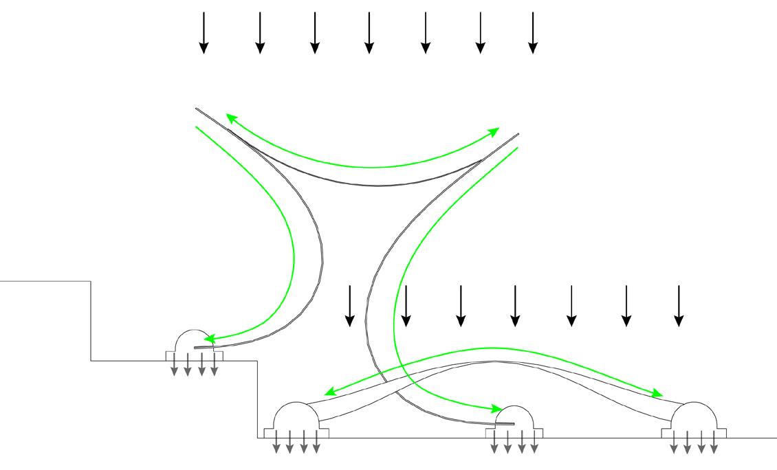
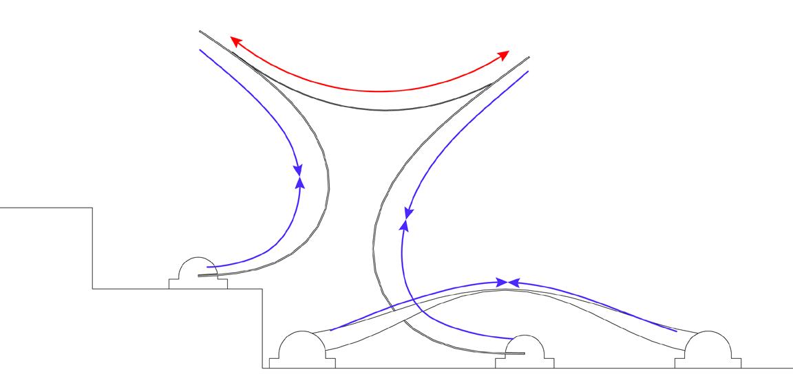


The fabrication process for the bottom beams allows for multiple beams to be bent simultaneously in opposing directions


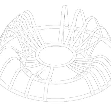
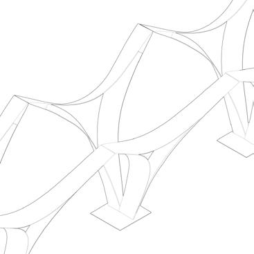
The Structural system for the top elements relies on an interaction between elements acting in compression and elements acting in tension
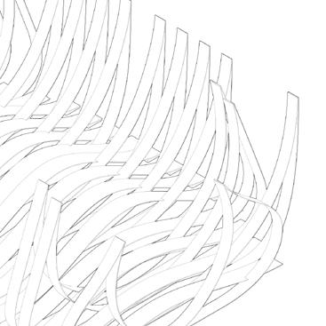
Our final design is composed of interlocking elements which alternatively act together and as separate seating spaces
10
Fig. 19
Fig. 20
Fig. 21
Load path and Axial Stress Diagrams
Exploded drawing of final proposal with contributions from groups highlighted
Photos of final model
Fig. 19
Fig. 20
Load Path Diagram
Axial Stress Diagram
Fig. 21
Beyond Isolation Competition
As a team we were briefed to design in order to address the issue of loneliness in contemporary elderly homes. Our proposal for Beyond Isolation sees the reuse of a listed British heritage building called the Broomfield house which is located in the borough of Enfield in London. To overcome the issues of loneliness we would like to propose a mode of living that sees the elderly at the heart of a community. In proximity to the facilities which they need and given the liberty to live their own lives.
The Broomfield house has suffered fires and as such is in a state of disrepair - left to be caged away by scaffolding for the indeterminate future. Rather than being preserved as it currently is, it should be opened up to the community and given new life.
The historic building would be integrated as a flexible space that could encompass weekly markets, gathering spaces for the community, performances or daycare.


Mapping of site and diagram of Broomfield’s history
Plan and section of proposal

11 Section AA’ A A’ New Proposal Broomfield after fires in 2017 Broomfield was first built in 1550s
Fig. 22
Fig. 23
Fig. 24
Renders of exterior and marketplace
Fig. 22
Fig. 23
Fig. 24
Models
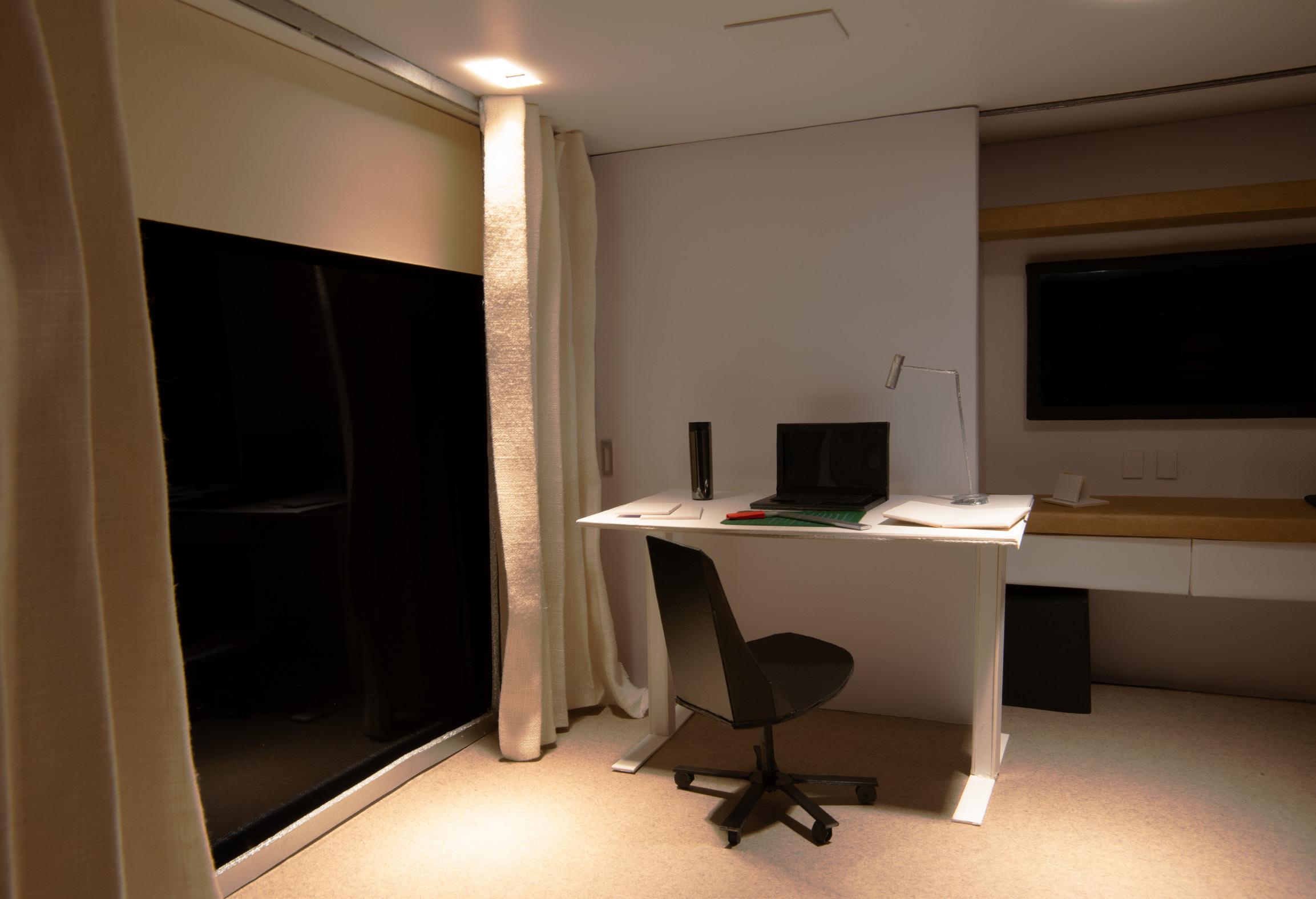
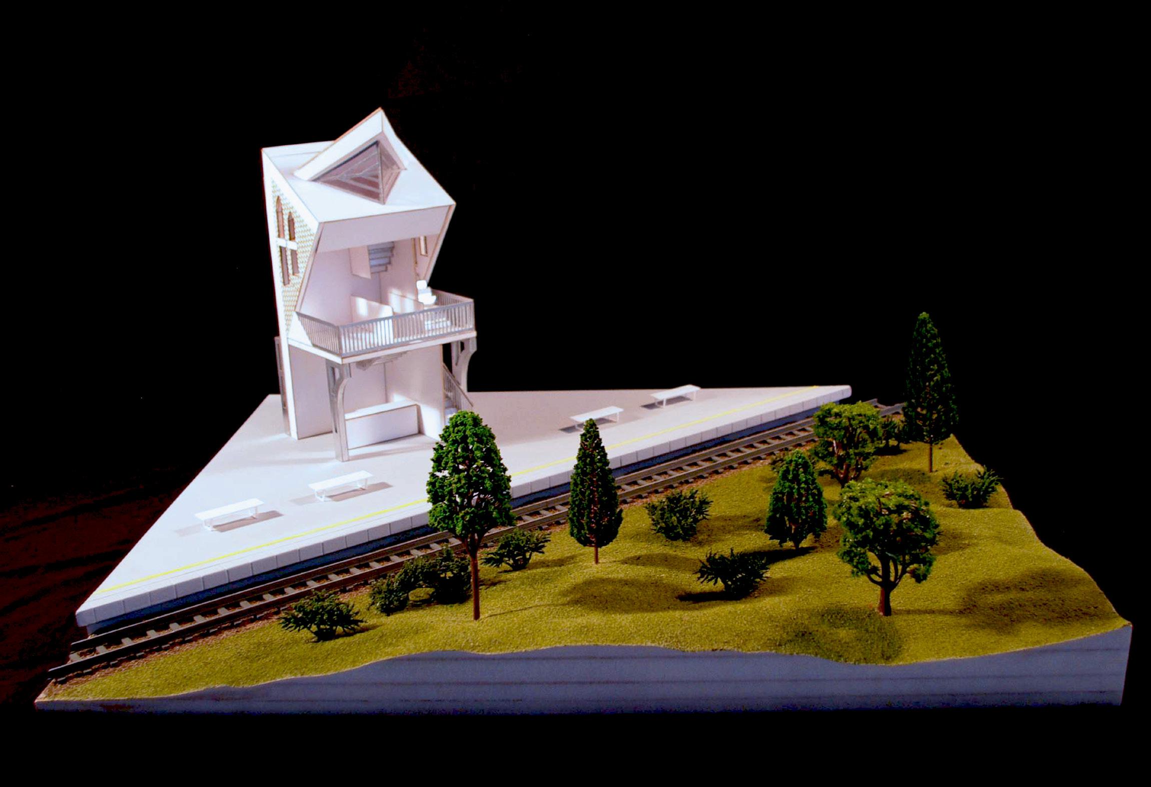
These are modelling projects from different years to showcase my modelling process and design skills through sketching.



12
Fig. 25
Fig. 26
Final photo of my COVID work space at home
Final photo of model proposing a railway cafe
Fig. 25
Fig. 26
Scale 1:50
Scale 1:20
Warren and Mahoney Internship
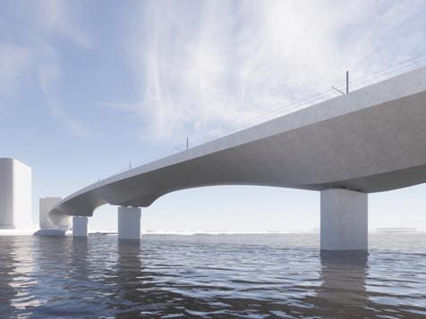
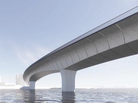
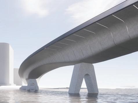
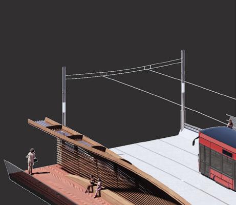
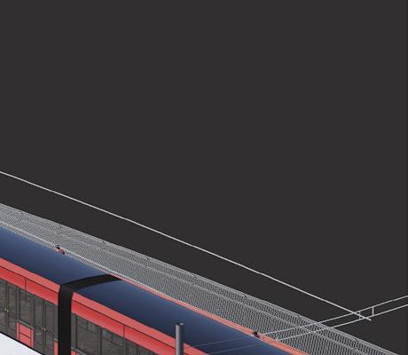
Sydney Light Rail Bridge | RIBA Stage 2-3 Equivalent During my internship experience worked on a pedestrian and lightrail bridge project in Sydney. On this project provided design, digital modelling, and documentation assistance on the project. used the Adobe Suite, Enscape, and Rhino to produce diagrams and renders.






13
Mahoney
Warren
and
Light Rail REFINEMENT OPPORTUNITIES USE CONSISTENT SPANS TO CREATE VISUAL SYMMETRY AND REDUCE NUMBER OF PIERS IN WATER MINIMISE VISUAL IMPACT OF PILE CAPS SCULPT UNDERSIDE OF DECK FOR SHADOW EFFECTS INTEGRATE REST AREAS WITH OUTWARD FACING VIEWS SIMPLE AND ELEGANT PIER DESIGN XXX XX CURVED ALIGNMENT FOR DYNAMIC FORM REDUCE WIDTH OF BRIDGE DECK
Scheme - Elevation Diagram Baseline Scheme - Visualisation Warren and Mahoney Parramatta Light Rail Wentworth Bridge
BASELINE ALIGNMENT Straight REFINED ALIGNMENT Curved Profiles Tapered box + detached pier + straight balustrade Scooped box + blended pier + angle-in balustrade Rounded box + tapered Pier + angle-out Balustrade Rounded box + Split pier + angle-in balustrade Preferred Option Rounded box + detached pier +angle out balustrade Expressed joints Baseline scheme Split box + tapered pier Variable Dimension
Parramatta
Baseline
Alignment
Fig. 27
Fig. 28
Render and renders of different iterations of bridge 3.95m 2.4m
Refinement Plan for alignment of bridge. Opportunities for refinement of baseline scheme and proposed design options Sectional
Fig. 27
Fig. 28
ADAM Architecture Part 1 Work Experience
During my current time at ADAM I have worked on a range of residential projects across stages 2-4.
Private Residential in Notting Hil | Stage 3-4
Helped assist in fire strategy, small powers, lighting, sections for demolition and proposed designs. Designing also an external door with sash windows and a concealed RWP, producing a joinery package along with window and door schedules.
Private Residential in Belgravia | Stage 2-4
Produced a BIM model for sectional renders and a base for later technical design. Assisted on spatial coordination updating plans in correspondence with feedback from structural and MEP engineers, fire marshals. Worked on fenestration plans and ventilation/heating plans.
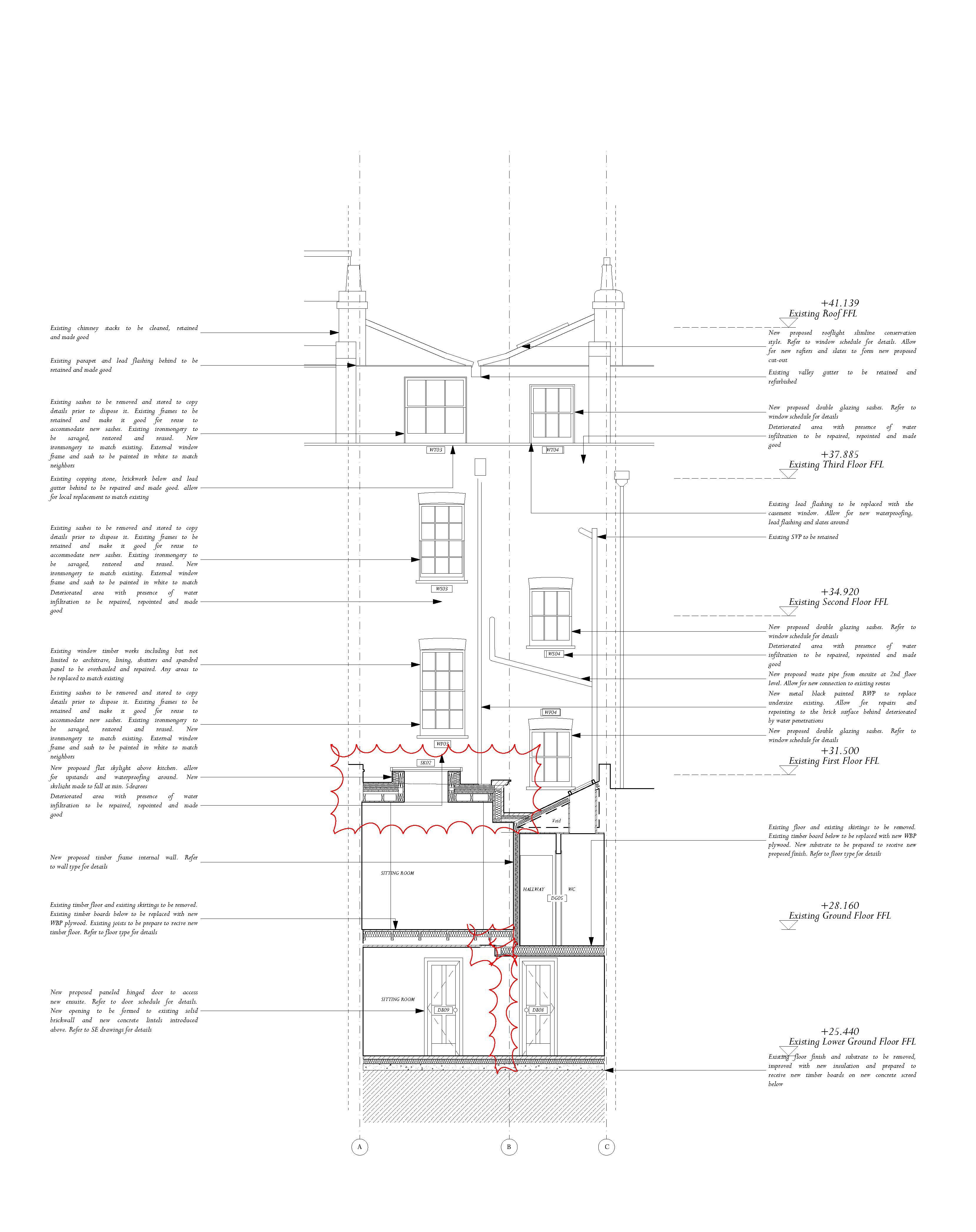
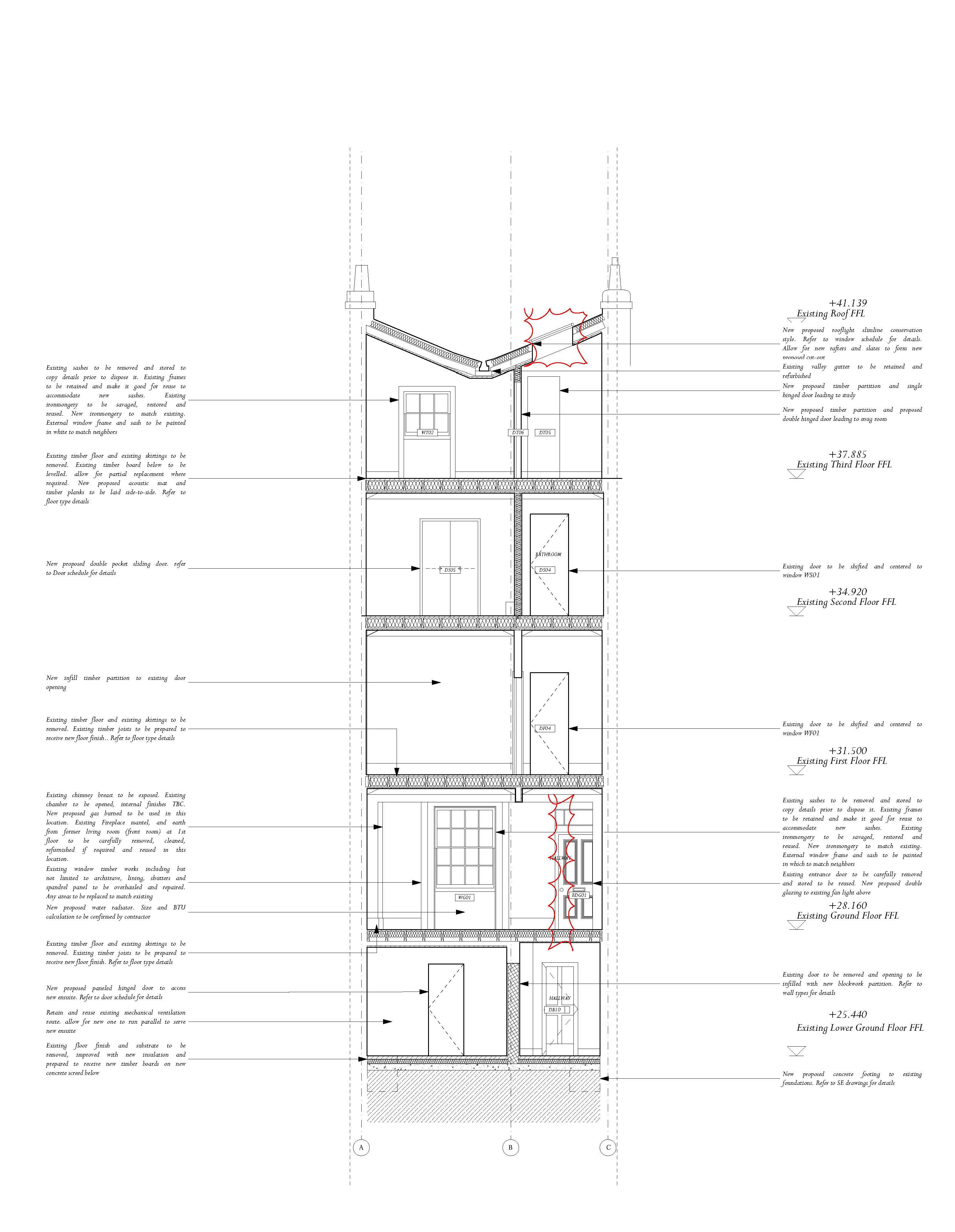 Fig. 29 Proposed Sections for Notting Hill Project



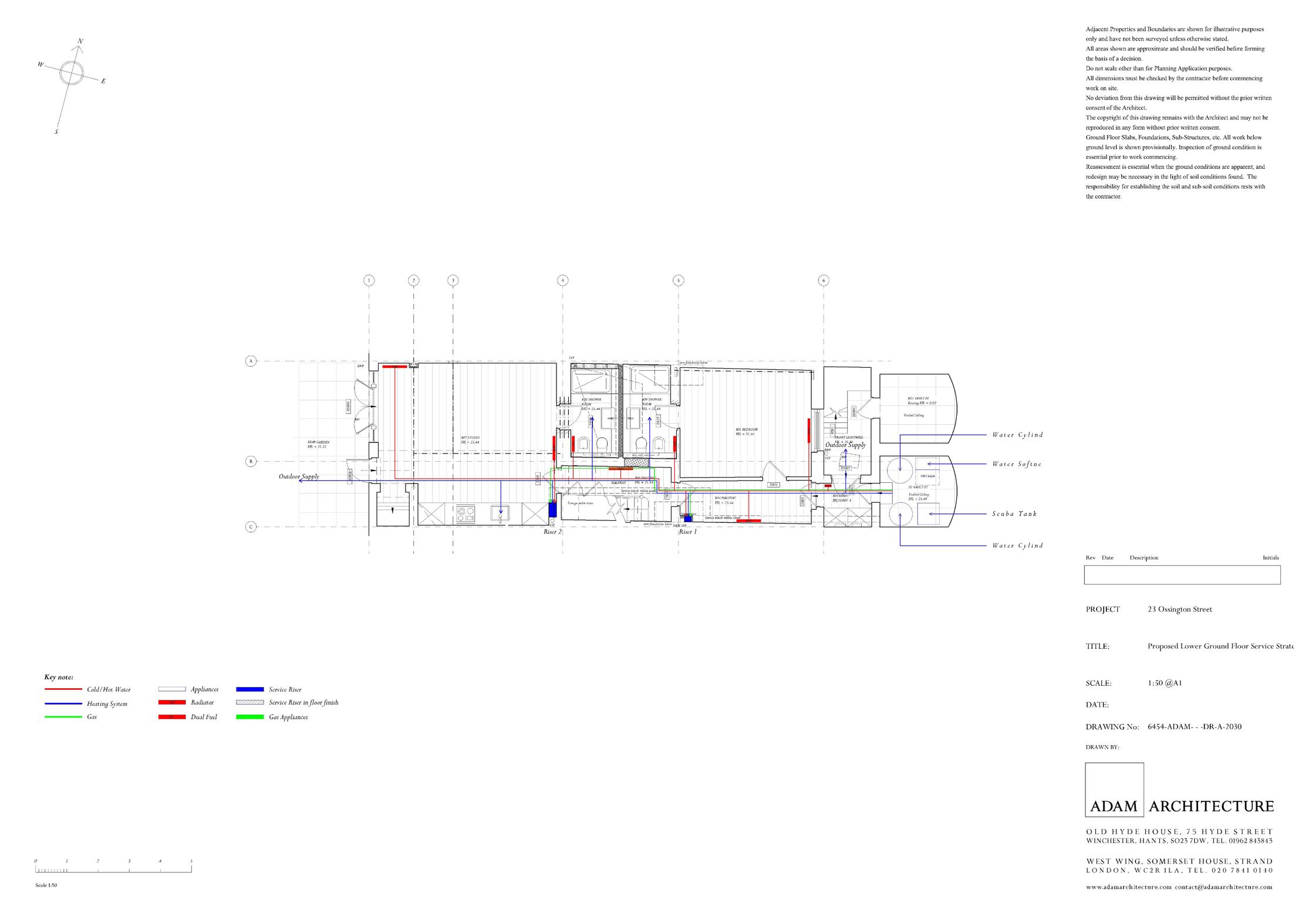 Fig. 30 Series of plans for Notting Hill project including Lighting, Small Powers, Service Strategy, and Fire Strategy.

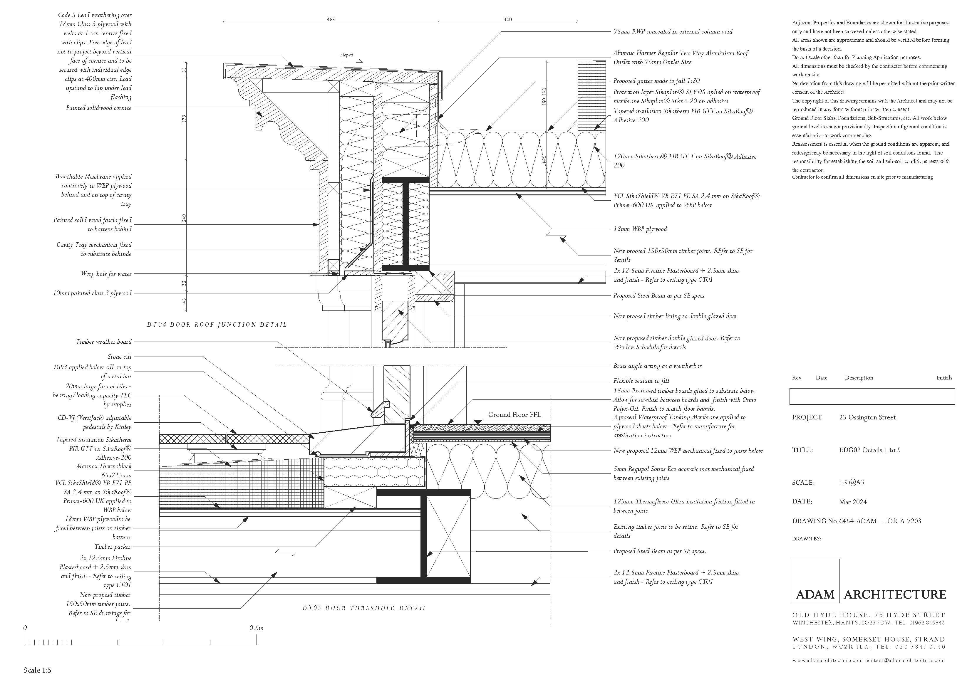
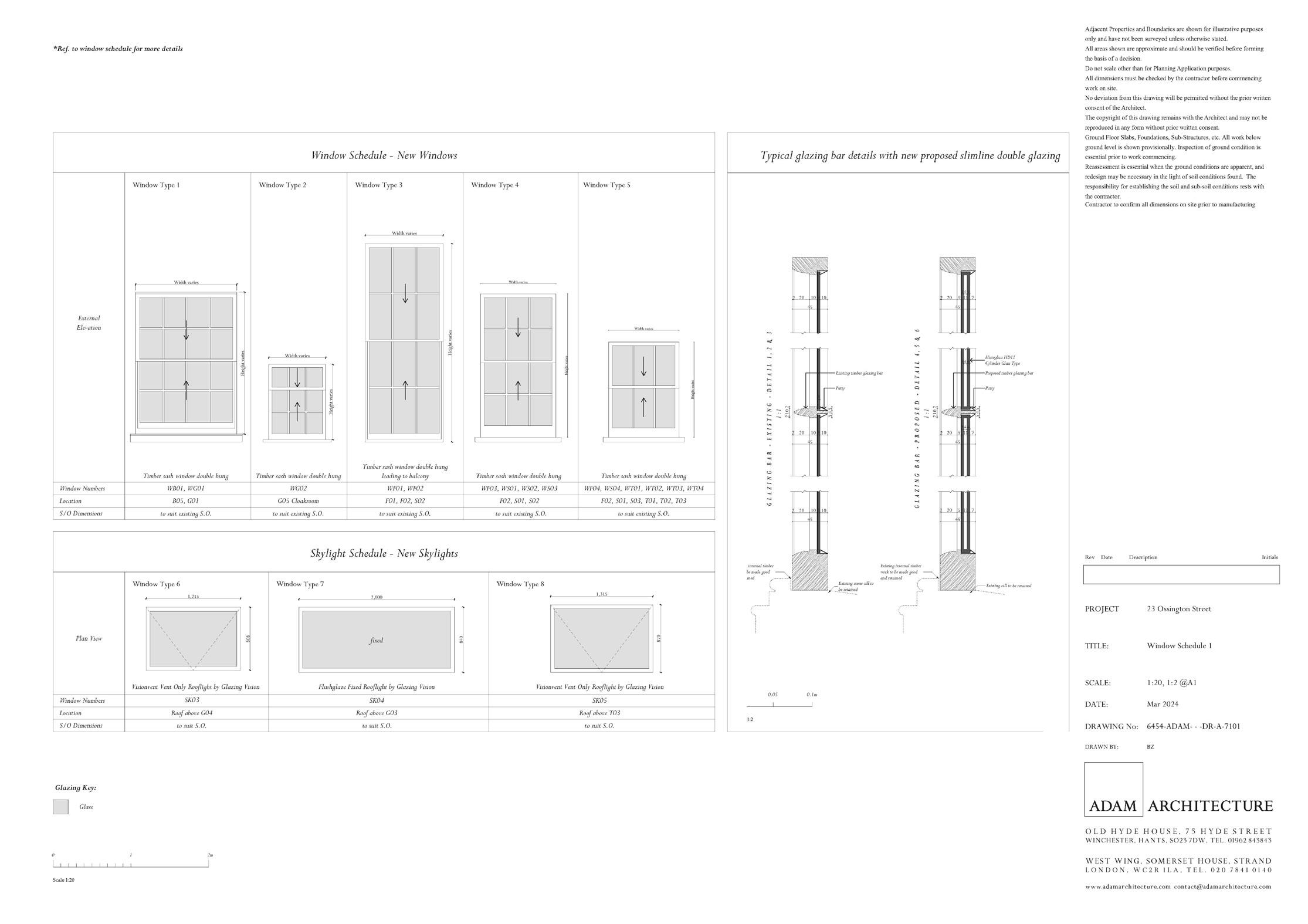
 Fig. 31 A joinery package for a custom door with door frame and glazing details
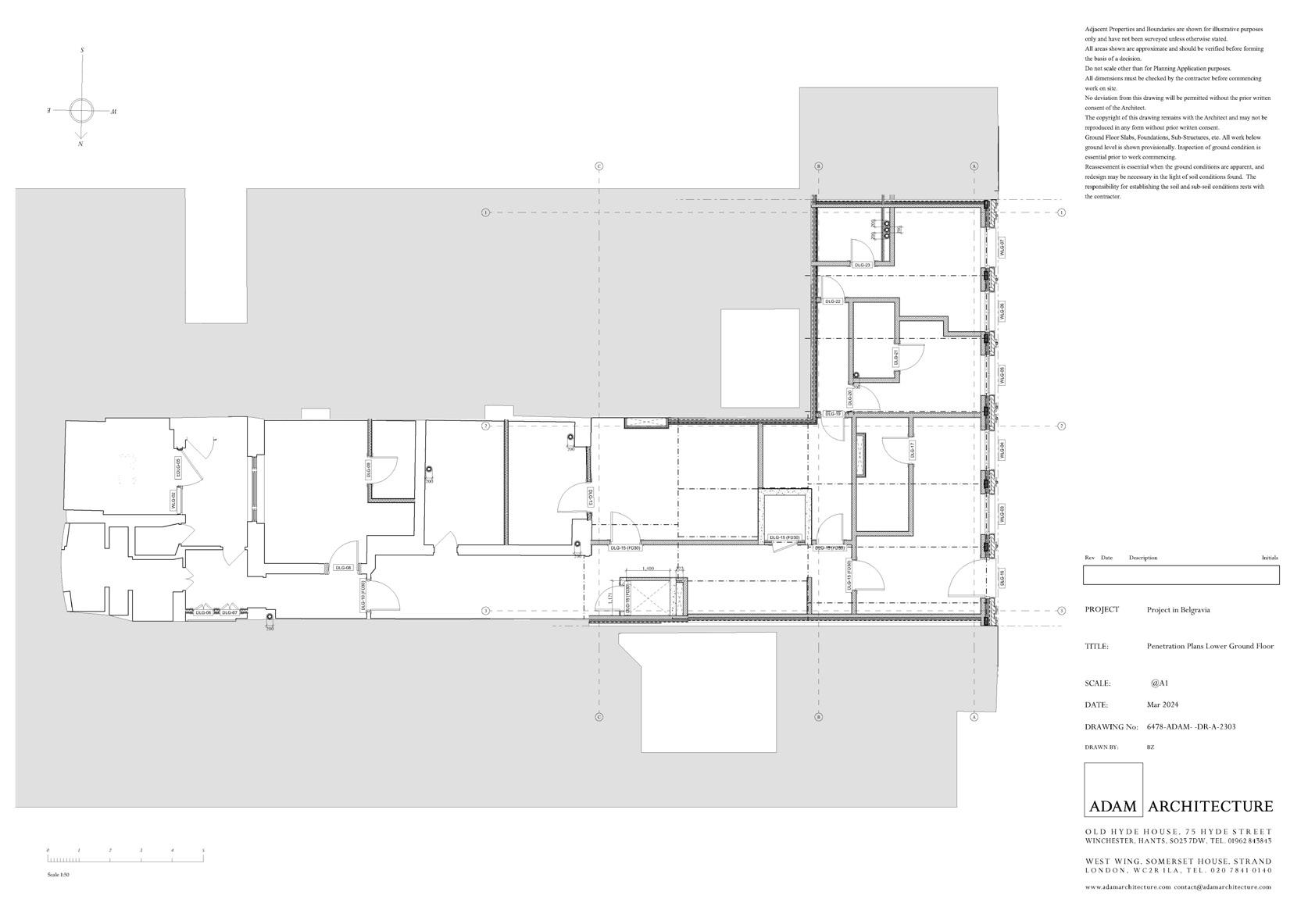


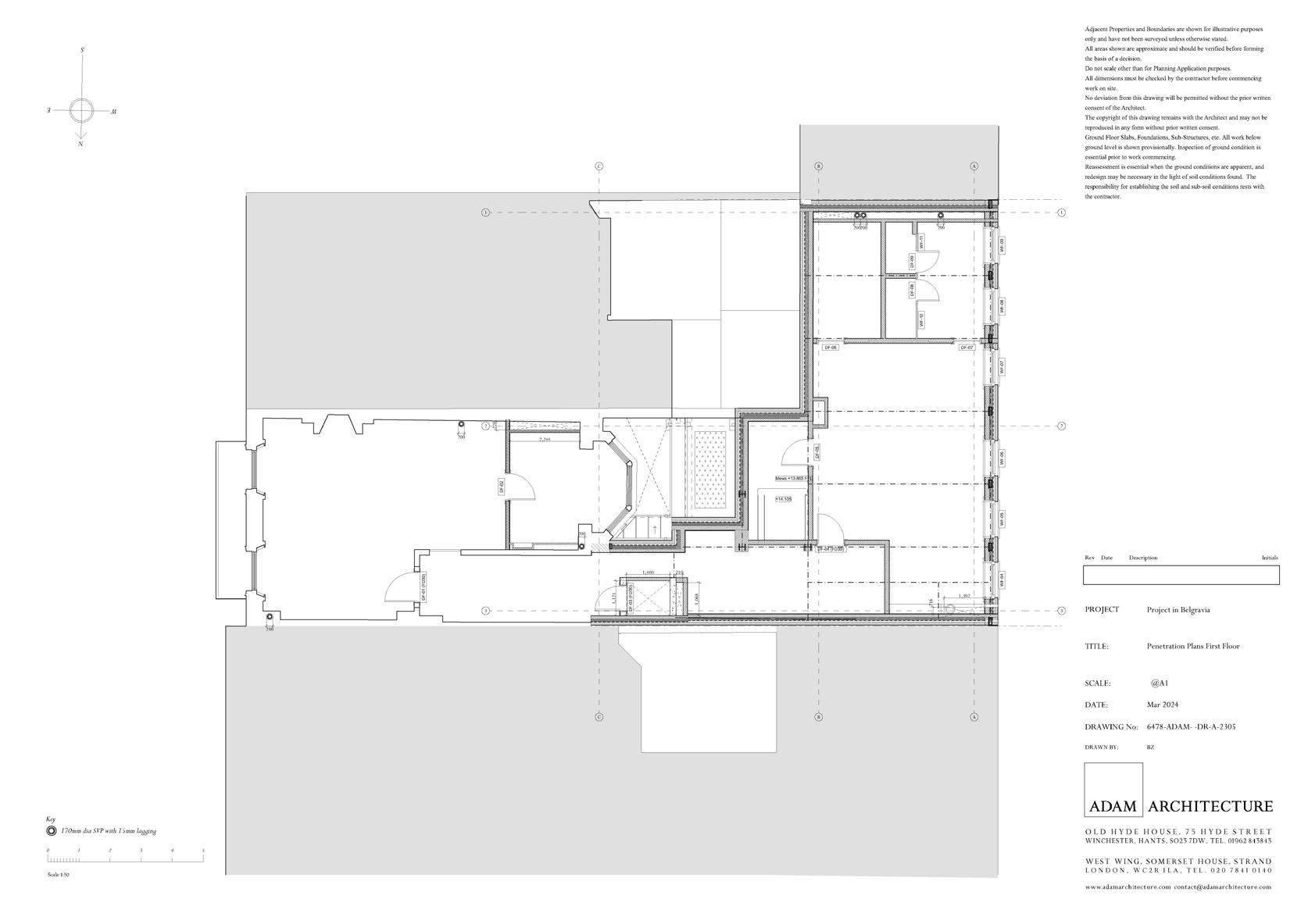
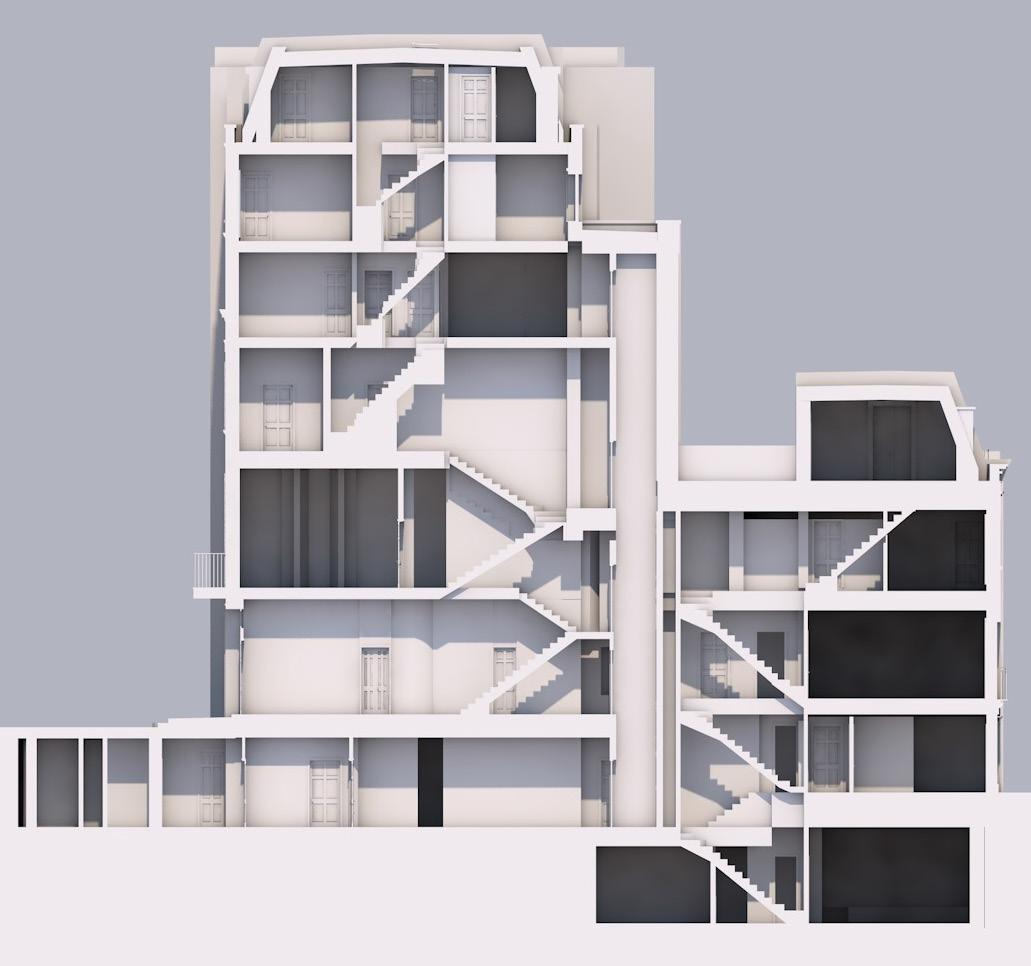 Fig. 32 Sectional Renders and Penetration plans for the Belgravia Project
Miscellaneous
Work from 2020-2021
These are a collection of personal works that reflect my interests outside of academia. Sculpture, drawing, and painting are all mediums to explore texture, color, and form.
With graphite drawings and oil paintings like to test my technical rigour and accuracy in capturing light, volume, and form.
I also worked on a light sculpture for a personal project, playing with material found and a filament bulb to create this themed light.


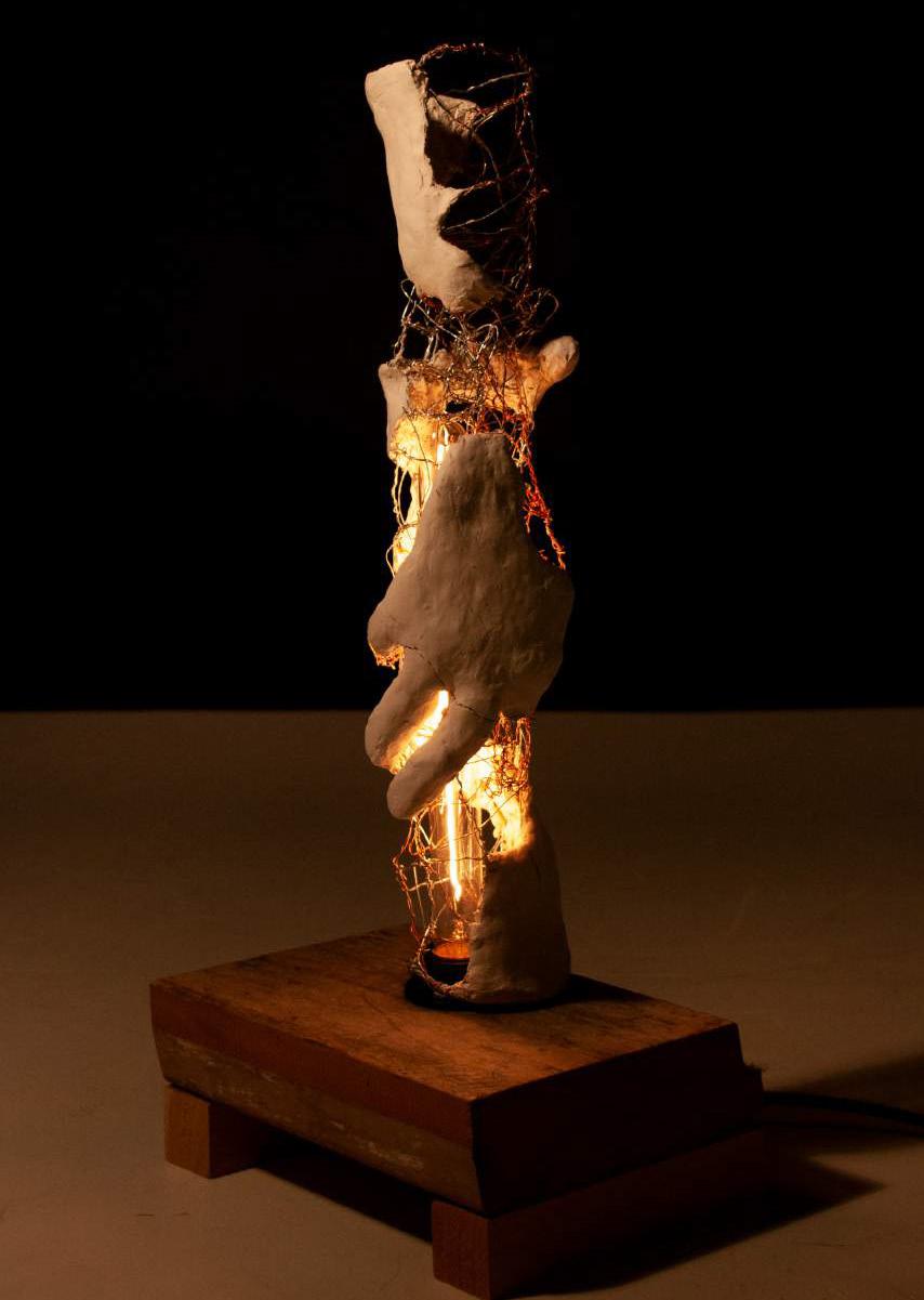

 Fig. 33
Fig. 34
Fig. 35
Still Life with pencil Oil Study of Taxi Driver still Light sculpture
Fig. 33
Fig. 34
Fig. 35
Fig. 33
Fig. 34
Fig. 35
Still Life with pencil Oil Study of Taxi Driver still Light sculpture


 Fig. 12 Sequence of collages illustrating phases of cleaning the station niches and their filling
Fig. 10
Fig. 11
Technical drawings of proposed inhabitation with external view, internal view. As well as station plan + different plans at different heights + Axonometric of proposal
Coloured Plaster Site Model with 3D-Printed Proposal showing the space within and the stairs to traverse the levels inside the nest.
Fig. 10
Fig. 12


 Fig. 29 Proposed Sections for Notting Hill Project


 Fig. 30 Series of plans for Notting Hill project including Lighting, Small Powers, Service Strategy, and Fire Strategy.


 Fig. 31 A joinery package for a custom door with door frame and glazing details


 Fig. 32 Sectional Renders and Penetration plans for the Belgravia Project


 Fig. 33
Fig. 34
Fig. 35
Still Life with pencil Oil Study of Taxi Driver still Light sculpture
Fig. 33
Fig. 34
Fig. 35
Fig. 33
Fig. 34
Fig. 35
Still Life with pencil Oil Study of Taxi Driver still Light sculpture