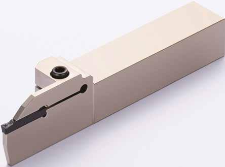
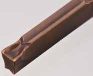
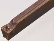
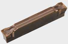
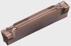
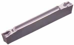
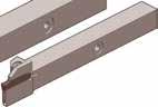
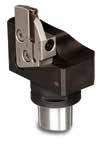
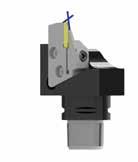
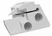
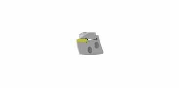
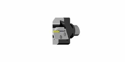
Series for External Machining for Small Lathes Series
3,04,05,0 6,07,08,0
Grooving Tool Holders
For External Machining (L Type)
Series for External Machining (L Type)
Grooving Cassettes
Cassettes for Radial Machining
Series for Face Machining
For Face Machining
Grooving Tool Holders
Grooving Tool Holders
Series for Necking
For Necking
Notes
for Undercutting
Distance between Workpiece and Necking
Tips for Necking
The recommended cutting conditions for necking are the same as grooving with RN type chipbreaker and edge width. To prevent interference with the work material, do not use the holder for less than the minimum cutting diameter (DMIN) as specified for GNGN type holders.
For face grooving, use cutting conditions closer to the lower limit of the recommended cutting conditions to ensure that chips are long.
For face grooving, use cutting conditions closer to the lower limit of the recommended cutting conditions to ensure that chips are long.
For face grooving, use cutting conditions closer to the lower limit of the recommended cutting conditions to ensure that chips are long.
Recommended Cutting Conditions
In cut-off applications, reduce the feed rate to around 30% to 50% near the centre of the workpiece.
In cut-off applications, reduce the feed rate to around 30% to 50% near the centre of the workpiece.
In cut-off applications, reduce the feed rate to around 30% to 50% near the centre of the workpiece.
As there is less space for chip evacuation when machining internal diameters (particularly small bore diameters), ML/GL/GF Type chipbreakers are recommended.
As there is less space for chip evacuation when machining internal diameters (particularly small bore diameters), ML/GL/GF Type chipbreakers are recommended.
As there is less space for chip evacuation when machining internal diameters (particularly small bore diameters), ML/GL/GF Type chipbreakers are recommended. Modifications to inserts and holders are required to perform machining such as radius grooving when using the RG type chipbreaker with the
Modifications to inserts and holders are required to perform machining such as radius grooving when using the RG type chipbreaker with the GNDF type holder for Recommended Cutting Conditions
Modifications to inserts and holders are required to perform machining such as radius grooving when using the RG type chipbreaker with the GNDF type holder for
Work Material P Carbon / Alloy Steel M
Grooving Tool Holders GND Series
Details – Holders
External Multi-Purpose
External Grooving
Grooving/Cut Off/ Turning/Profiling
Grooving/Cut Off/ Turning/Profiling
Grooving/Cut Off
External Deep Grooving Grooving/Cut Off
External L-Styled (Side Cut)
Multi-Purpose
External L-Styled (Side Cut)
Deep Grooving
Grooving/Turning/Profiling
Grooving
Necking Necking
Internal Grooving
Internal Grooving
Face Grooving
L-Shaped Tools for Facing
Grooving/Turning/ Profiling
Grooving/Turning/ Profiling
Grooving/Turning/ Profiling
Grooving/Turning/ Profiling
Cassette for Polygon Holder Radial Grooving
Cassette for Polygon Holder Face Grooving
To ensure maximum rigidity, use the multi-purpose type
Identification Details – Inserts
066,02020,0 088,02323,0 1010,02525,0
Multi-Purpose: General Feed
Multi-Purpose: Low Feed
Grooving: General Feed
Grooving: Low Feed
Grooving: Low Cutting Forces
Cut-Off
Cut-Off: Low Cutting
Copying: General Feed
Multi-Purpose: General Feed
Multi-Purpose: General Feed
Grooving Tool Holders GND Series
Key Points for Face Machining
Holder Selection Precautions for Groove Expansion
Recommended Chipbreaker:
Select a holder so that the outer diameter of the first groove to be machined comes within the range of maximum and minimum grooving diameter of the holder.
Precautions for Turning
If the first groove meets the range of the effective grooving diameter during groove expansion, the grooving diameter will not be limited for the second and later passes.
Recommended Chipbreaker:
Considering the rigidity of the holder, we recommend machining from the outside to the inside.
If machining is performed toward the outside, the wall thickness remaining on the principal force side will become thinner, which reduces the rigidity of the holder.
- If the first groove meets the range of the effective grooving diameter in face turning, the grooving diameter will not be limited for the second and later passes.
- Select the chipbreaker of the lower limit side of the recommended cutting conditions and straight chips before evacuation. (In face grooving, broken chips easily get stuck in grooves, which causes problems.)
- When breaking chips, step feed is required.
Key Points for Internal Machining
Precautions for Internal Machining
Recommended Chipbreaker:
If the prepared hole diameter is small, use an ML or GL low-feed chipbreaker, each of which reduces chip curl diameter, to ensure adequate chip evacuation.
Work Material: Holder: Insert: Cutting Conditions:
15CrMo5 (Ø 25 mm)
GNDI R2532 T306
GCM N300
vc=100 m/min, f=0,10 mm/rev, ap=3,0 mm, wet
Chip shapes differ between internal and external machining even under the same cutting conditions.
Work Material: Holder: Insert: Cutting Conditions: 15CrMo5
GNDL R2525M 320
GCM N3002 GG
vc=100 m/min, f=0,10 mm/rev, ap=5 mm, wet
Grooving Tool Holders
Precautions for Grooving Tool Holders GND Series
Notes on how to Attach Inserts
Remove any foreign particles or oil from the insert seat before attaching the insert. Ensure the seat location is clean and free of damage.
Slide the insert level over its seat.
Push the insert with its opposite end (the holder side) firmly against the insert stop end. The recommended tightening torque is 5 N m. Tightening above the recommended torque may damage the insert or the holder which could cause injury and other accidents.
Notes on how to Apply Holders
Remove any foreign particles or oil from the tool post before attaching the holder.
Ensure the seat location is clean and free of damage.
Attach the holder so that the insert is perpendicular to the workpiece.
Set holder with shortest possible overhang.
When grooving or turning, adjust the center height of the cutting edge to as close ±0 mm as possible. (Within ±0,1 mm is recommended)
Incorrect center height adjustment may cause chattering. (In cut-off applications, adjust the center height of the cutting edge to a value from 0,0 to +0,2 mm). A lower center height will result in larger nip at the center.
Attach at right angle to workpiece. Set with short overhang
Notes on Setting Coolant Supply NozzleMaximum Depth of Cut
Set the coolant supply nozzle so that coolant can be supplied from the top of the upper clamp unit.
Maximum depth of cut when pulling up with RG chipbreaker
Key Points of Internal Coolant-Type Holders for Small Lathes
The insert for internal coolant-type 12 mm and 16 mm holders for small lathes can be replaced from either the top or
Grooving Tool Holders GND
Key Points for Connecting Hoses and Connectors
Connecting Hoses and Connectors
GNDM-JE (European standard)
Apply sealant such as commercial sealing tape to the piping connection parts.
GNDM-JE type holders have a plug (XP02-E) mounted on the holder back end at shipping. (see fig.1) When piping from the holder back end, mount a grub screw (BT0505-E) on the bottom of the holder for use. (see fig. 2)
Connecting Hoses and Connectors (for Small Lathes)
Apply sealant such as commercial sealing tape to the piping connection parts. Refer to the figur below for mounting the plug during piping.
Holder with Hoseless Coolant Support
Direct coolant supply from the tool post is possible without a hose The plug will protrude a few millimeters when mounted to the side. A plug is attached when shipped. Remove this plug before supplying coolant without a hose.
Connector for Hoseless Coolant Supply
Remove the plug before supplying coolant without a hose. Cross Section of Connector
Mount the plugs (XP02) before supplying coolant without a hose.
Fig.
The plug will protrude a few millimeters when mounted to the side.
GNDM R/L 2020 X 418 JE ll 2020 110 202045,04,001836
GNDM R/L 2020 X 518 JE ll 2020 110 202045,05,001836
GNDM R/L 2020 X 618 JE ll 2020 110 202045,06,001836
GNDM R/L 2525 X 210 JE ll 2525100252533,62,001020
GNDM R/L 2525 X 418 JE ll 2525 110 252545,04,001836
GNDM R/L 2525 X 518 JE ll 2525 110 252545,05,001836
GNDM R/L 2525 X 618 JE ll 2525 110 252545,06,001836
Holder with Internal Coolant
J-HOSE-G1/8-G1/8-200-E l 200G1/8G1/81
J-HOSE-G1/8-G1/8-300-E l 300G1/8G1/81
Parts (Connector)
J-G1/8-G1/8-00-E l G1/8 G1/81
J-G1/8-G1/8F-90-E l G1/8 G1/82
J-G1/8-G1/8-90-E l G1/8 G1/83
Fig. 1 Fig. 1
Fig. 2
Fig. 3
Grooving Tool Holders GNDM-JE
Inserts for GNDM-JE
Grooving Tool Holders
Type
GNDL R/L 2020 K 1.2516 ll 2020125202038,01,251632 GCM N125005 GF
GNDL R/L 2020 K 1.516 ll 2020125202038,01,501632 GCM N150005 GF
GNDL R/L 2020 K 220 ll 2020125202044,52,002040 GCM □20-
GNDL R/L 2020 K 320 ll 2020125202044,53,0020(18) 40 GCM □
GNDL R/L 2020 K 425 ll 2020125202050,04,0025(23)
GNDL R/L 2020 K 525 ll 2020125202050,05,0025(23)
GNDL R/L 2020 K 625 ll 2020125202050,06,0025(23)
GNDL R/L 2525 M 1.2516 ll 2525150252540,01,251632 GCM N125005 GF
GNDL R/L 2525 M 1.516 ll 2525150252540,01,501632 GCM N150005 GF
GNDL R/L 2525 M 220 ll 2525150252544,52,002040
GNDL R/L 2525 M 320 ll 2525150252544,53,0020(18)
GNDL R/L 2525 M 425 ll 2525150252550,04,0025(23)
GNDL R/L 2525 M 525 ll 2525150252550,05,0025(23)
GNDL R/L 2525 M 625 ll 2525150252550,06,0025(23)
GNDL R/L 3225 P 320 3225170253244,53,0020(18)
GNDL R/L 3225 P 625
GNDL R/L 3225 P 725
GNDL R/L 3225 P 825
GNDL R/L 3232 P 320 ll 3232170323244,53,0020(18)
Spare Parts
GNDLS R/L 2020 K 216 ll 20201253820252,016
GNDLS R/L 2020 K 316 m l 20201253820253,016
GNDLS R/L 2525 M 218 ll 25251504525252,018
GNDLS R/L 2525 M 318 ll 25251504525253,018
GNDLS R/L 2525 M 423 ll 25251505025254,023
GNDLS R/L 2525 M 523 mm 25251505025255,023
GNDLS R/L 2525 M 623 l m 25251505025256,023
Spare Parts
Grooving Tool Holders
Fig.
Grooving Tool Holders
GNDL-JE Type
External Deep Grooving and Cut-Off
GNDL-JE
Spare Parts
RLHBLFWFHFLHCWCDX
GNDL R/L 2020 X 220 JE ll 2020 110 202044,52,002040
GNDL R/L 2020 X 320 JE ll 2020 110 202044,53,002040
GNDL R/L 2020 X 425 JE ll 2020 115 202050,04,002550
GNDL R/L 2020 X 525 JE ll 2020 115 202050,05,002550
GNDL R/L 2020 X 625 JE ll 2020 115 202050,06,002550
GNDL R/L 2525 X 220 JE ll 2525 110 252544,52,002040
GNDL R/L 2525 X 320 JE ll 2525 110 252544,53,002040
GNDL R/L 2525 X 425 JE ll 2525 115 252550,04,002550
GNDL R/L 2525 X 525 JE ll 2525 115 252550,05,002550
GNDL R/L 2525 X 625 JE ll 2525 115 252550,06,002550
Parts (Hose)
J-HOSE-G1/8-G1/8-200-E l 200G1/8G1/81
J-HOSE-G1/8-G1/8-300-E l 300G1/8G1/81
Parts (Connector)
Fig.
Grooving Tool Holders GNDL-JE
Inserts for GNDL-JE
Fig.
Grooving Tool Holders
Type
Necking
GNDN
Necking Necking Above figures show right hand tools.
Holders
GNDN R/L2020 K 215-020 mm 20201252320303,0202,01,50,64 GCM N2010 RN
GNDN R/L2020 K 320-020 mm 20201252320303,0203,02,00,79 GCM N3015 RN
GNDN R/L2020 K 430-030 mm 20201252420324,0304,03,01,29 GCM N4020 RN
GNDN R/L2020 K 535-030 mm 20201252520355,0305,03,51,44 GCM N5025 RN
GNDN R/L2020 K 640-030 mm 20201252520355,0306,04,01,59 GCM N6030 RN
GNDN R/L2525 M 215-020 mm 25251502825303,0202,01,50,64 GCM N2010 RN
GNDN R/L2525 M 320-020 mm 25251502825303,0203,02,00,79 GCM N3015 RN
GNDN R/L2525 M 430-030 mm 25251502925324,0304,03,01,29 GCM N4020 RN
GNDN R/L2525 M 535-030 mm 25251503025355,0305,03,51,44 GCM N5025 RN
GNDN R/L2525 M 640-030 mm 2525 1503025355,0 306,04,01,59 GCM N6030 RN
Inserts for GNDN
BX05205,0LH040
BX05205,0LH040
Fig. 2
Grooving Tool Holders
R/L2020K-432 2020125202048.04.03264
R/L2020K-532 2020125202048.05.03264
R/L2020K-632 2020125202048.06.03264
GNDXL R/L2525M-226 2525150252542.02.02652
R/L2525M-332 2525150252548.03.03264
R/L2525M-432 2525150252548.04.03264
R/L2525M-532 2525150252548.05.03264
R/L2525M-632 2525150252548.06.03264
Select holders and inserts with matching width of cut (CW). Only 1-cornered inserts can be used. Refer to P33 for applicable inserts. The maximum groove depth CDX is the figure during grooving. For maximum depth of cut during traverse cutting and profiling, refer to P11. Grooving / Traverse Cutting (1-cornered)
Grooving Tool Holders
GNDF Type
Spare Parts
Use for multi-purpose or profiling insert for turning (wide grooves).
Holders
GNDF R/L 2020 K 312-035 ll 2020125202035,635–453,012
GNDF R/L 2020 K 312-040 ll 2020125202035,640–553,012
GNDF R/L 2020 K 318-050 ll 2020125202041,650–703,018
GNDF R/L 2020 K 318-065 ll 2020125202041,6 65–1003,018
GNDF R/L 2020 K 318-090 ll 2020125202041,6 90–1503,018
GNDF R/L 2020 K 318-140 ll 2020125202041,6140–2003,018
GNDF R/L 2020 K 318-180 ll 2020125202041,6180–3003,018
GNDF R/L 2020 K 418-040 ll 2020125202041,640–554,018
GNDF R/L 2020 K 423-050 ll 2020125202046,650–704,023
GNDF R/L 2020 K 423-065 ll 2020125202046,665–904,023
GNDF R/L 2020 K 423-085 l m 2020125202046,6 85–1304,023
GNDF R/L 2020 K 423-125 m l 2020125202046,6125–2004,023
GNDF R/L 2020 K 423-180 mm 2020125202046,6180–3004,023
GNDF
2020125202046,6 280–10004,023
GNDF R/L 2020 K 523-050 mm 20 20125202046,650–705,023
GNDF R/L 2020 K 523-065 m l 20 20125202046,665–905,023
GNDF R/L
GNDF R/L 2020 K 523-125 ll 20 20125202046,6125–2005,023
GNDF R/L 2020 K 523-180 mm 20 20125202046,6180–3005,023
GNDF R/L 2020 K 523-280 mm 20 20125202046,6 280–10005,023
GNDF R/L 2020 K 623-050 mm 20 20125202046,650–756,023
GNDF R/L 2020 K 623-070 mm 20 20125202046,6 70–110 6,023
GNDF R/L 2020 K 623-100 m l 20 20125202046,6100–2006,023
GNDF R/L 2020 K 623-180 mm 20 20125202046,6180–3006,023
GNDF R/L 2020 K 623-280 mm 20 20125202046,6 280–10006,023
GNDF R/L 2525 M 312-035 ll 2525150252535,635–453,0 12
GNDF R/L 2525 M 312-040 ll 2525150252535,640–553,0 12
GNDF R/L 2525 M 318-050 ll 2525150252541,650–703,018
GNDF R/L 2525 M 318-065 ll 2525150252541,6 65–1003,018
GNDF R/L 2525 M 318-090 ll 2525150252541,690–1503,018
GNDF R/L 2525 M 318-140 ll 2525150252541,6140–2003,018
GNDF R/L 2525 M 318-180 ll 2525150252541,6180–3003,018
GNDF R/L 2525 M 423-050 ll 2525150252546,650–704,023
GNDF R/L 2525 M 423-065 ll 2525150252546,665–904,023
GNDF R/L 2525 M 423-085 ll 2525150252546,6 85–1304,023
GNDF R/L 2525 M 418-040 ll 2525150252541,640–554,018 GCM N40-□□ BX05205,0LH040
GNDF R/L 2525 M 423-125 ll 2525150252546,6125–2004,023
GNDF R/L 2525 M 423-180 ll 2525150252546,6180–3004,023
GNDF R/L 2525 M 423-280 ll 2525150252546,6280–10004,023
GNDF R/L 2525 M 523-050 ll 2525150252546,650–705,023
GNDF R/L 2525 M 523-065 ll 2525150252546,665–905,023
GNDF R/L 2525 M 523-085 ll 2525150252546,6 85–1305,023
GNDF R/L 2525 M 523-125 ll 2525150252546,6125–2005,023
GNDF R/L 2525 M 523-180 ll 2525150252546,6180–3005,023
GNDF R/L 2525 M 523-280 ll 2525150252546,6 280–10005,023
GNDF R/L 2525 M 623-050 l m 2525150252546,650–756,023
GNDF R/L 2525 M 623-070 ll 2525150252546,6 70–110 6,023
GNDF R/L 2525 M 623-100 ll 2525150252546,6100–2006,023
GNDF R/L 2525 M 623-180 m l 2525150252546,6180–3006,023
GNDF R/L 2525 M 623-280 ll 2525150252546,6 280–10006,023
GNDI R/L 2532 T 206 ll 252320016322,06 GCM N20-□□ BH05165,0LH030
GNDI R/L 3240 T 210 ll 323025026402,010
GNDI R/L 2532 T 306 ll 252320016323,06
N20-□□ BH06166,0LH040
N30-□□ BH05165,0LH030
GNDI R/L 3240 T 310 ll 323025026403,010 GCM N30-□□ BH06166,0LH040
GNDI R/L 4050 T 311 ll 403830031503,0 11 GCM N30-□□
GNDI R/L 2532 T 406 ll 252320019324,06
N40-□□ BH05165,0LH030
GNDI R/L 3240 T 410 ll 323025026404,010 GCM N40-□□
GNDI
Select
Grooving Tool Holders GNDI Type
Inserts for GNDI
Fig. 1
Grooving Tool Holders
Spare
GNDIS R/L 1214 T 1526 mm 12 11 15030 9,0141,52,6
GNDIS R/L 1214 T 1536 mm 12 11 1503010,0141,53,6 GXM N150005S GF
N150005S GF BFTX0409N 3,4LT15
GNDIS R/L 1616 T 1536 mm 16151603511,5161,53,6 GXM N150005S GF
GNDIS R/L 1620 T 1546 mm 16151604014,5201,54,6
GNDIS R/L 2025 T 1566 mm 20191804019,0251,56,6
GNDIS R/L 1214 T 2026 mm 12 11 15030 9,0142,02,6
N150005S GF BFTX0511N 5,0LT20
N150005S GF
3,4LT15 GNDIS R/L 1214 T 2036 mm 12 11 1503010,0142,03,6
GNDIS R/L 1616 T 2036 mm 16151603511,5162,03,6
Grooving Tool Holders GNDIS Type
Inserts for GNDIS
Select holders and inserts with the same grooving width (CW).
Recommended Cutting Conditions
GCM and GCG inserts are not compatible.
Grooving / Cut-Off Machining / NeckingTraversing
Fig. 1
Grooving Tool Holders
Application
20CrMo5, Automotive Part, Face Profiling
Higher rigidity
Vibration reduction
Chip control - Wear resistance performance
GNDF R2525M 423-125
N4020 RG
C48, Machine Part, Cut-Off
X40CrVMo5-1, (45-48HRC), Machine Part, Cut-Off
Higher rigidity - Vibration reduction - Chip control
R2525M 425
C53, Cam Shaft Grooving / Finishing (Contin. to Heavy Interrupted)
Stable machining free of vibration!
conditions: GNDM L2525M
Stable machining free of vibration! Excellent chip control using the GND type. Holder: Insert: Grooving width:
34CrMo4, Tempered Material Hydraulic Component, Cut-Off
R2525M
Stable machining free of vibration! Excellent chip control using the GND type. No more unexpected breakage!
Stable chip control
Gear Shaft, Grooving / Pocketing
Higher rigidity - Vibration reduction - Chip control
GNDM R2020K 518
N5008 MG
mm v c = 150 m/min
= 0,1 mm/rev wet
Stable machining free of vibration! Excellent chip control using the GND type.
Grooving Tool Holders GND Series
34CrMo4, Crank, Cut-Off
Sintered Clutch Hub, Face Grooving
General Features
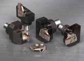
New grades and chipbreakers have been added to the already established GND grooving system with polygon shank and a flexible and economical cassette system for inserts. An array of chipbreakers improves the efficiency in chip control in various applications such as grooving, turning, profiling and cut-off.
Advantages
GND inserts for soft grooving from 2,0 - 6,0 mm width
Expanded grade selection with 9 different chipbreakers for a wide application range
Provides excellent chip control
Achieves stable long tool life
Cassette
Identification Details - Polygon-Toolholder
Note:
The right handed PSC40/50/63GM90R holder needs a left cassette.
The left handed PSC40/50/63GM90L holder needs a right cassette.
Handling
ATTENTION
To fix the cassette on the holder, please clamp the cassette at first with the inner torx screw.
* Dimension when using radial grooving cassettes.
Identification Details - Cassette
ISO-PSC Polygon Modular GND
Inserts for GNDCM
ISO-PSC Polygon Modular
GNDCM-JE
General Features
Cassette with Internal Coolant
The already established GND grooving system with polygon shank and a flexible cassette system for grooving inserts, has been extended by a version with internal coolant supply. The direct cooling at the cutting edge ensures excellent chip breaking and improves chip control during external grooving.
Advantages
External grooving cassettes with internal coolant supply
PSC Polygon holders straight and 90° with internal coolant supply
GND inserts for soft grooving from 2,0-6,0 mm grooving width
Provides excellent chip control
Depending on the coolant pressure, the tool life of the cutting edge will increase significantly