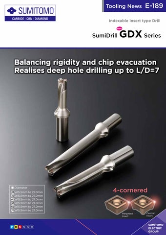
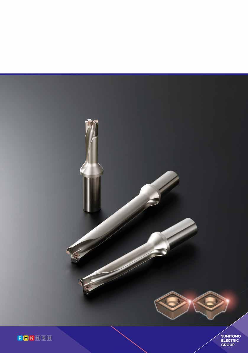
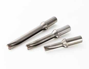
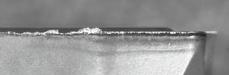
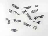
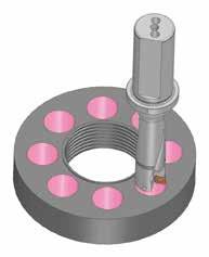
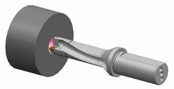
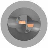
The SumiDrill GDX series sharply reduces machining vibration through high-rigidity holder design. Further, the individually optimised design of the peripheral and central inserts achieves excellent cutting balance and chip evacuation. Dramatically improved stability supports deep hole drilling up to L/D=7.
3D ø15.5 to 18.0 ø18.5 to 22.0 ø22.5 to 27.0 4D ø15.5 to 18.0 ø18.5 to 22.0 ø22.5 to 27.0 5D ø15.5 to 18.0 ø18.5 to 22.0 ø22.5 to 27.0 6D ø15.5 to 18.0 ø18.5 to 22.0 ø22.5 to 27.0
7D ø15.5 to 18.0 ø18.5 to 22.0 ø22.5 to 27.0
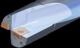
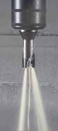
Proprietary groove design balances chip evacuation and holder rigidity at a high level.
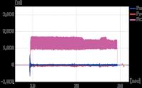
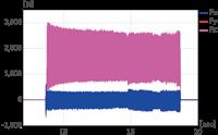
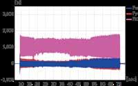
Machining vibration is effectively suppressed and cutting force reduced to realise stable deep hole drilling.
GDXT06T204P-G (ACU2500) Central Insert: GDXT06T206C-G (ACU2500) Cutting Conditions (5D Holder):
Vc = 150m/min f = 0.10mm/rev H = 85mm (Stop Hole) Internal Coolant Supply (Water soluble) (7D Holder): Vc = 150m/min f = 0.06mm/rev H = 140mm (Stop Hole) Internal Coolant Supply (Water-soluble)
¢ Dedicated Insert Design
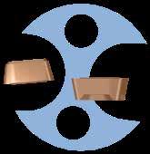
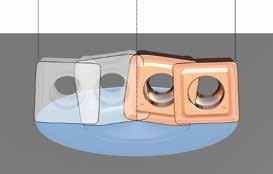
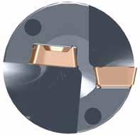
The central and peripheral insert designs have been individually optimised, improving stability with the optimal shape and relative positioning. Further, the wiper flat shape has been optimised to achieve excellent machined surface quality.
Dedicated insert design
Balanced design
Insert
Insert
Using simulations to create dedicated designs for the central insert and peripheral insert, cutting force has been rendered uniform
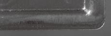
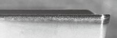
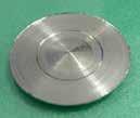
Machined Surface Quality
GDX series
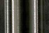
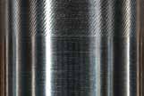
Competitor’s Product B Glossy surface with no scratches Undulating pattern
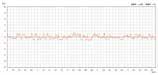
= 1.04μm
Work Material: S50C Tool: GDXH200D5S25-06 (ø20, 5D) Insert: Peripheral Insert: GDXT06T204P-G (ACU2500) Central Insert: GDXT06T206C-G (ACU2500) Cutting Conditions: Vc = 150m/min f = 0.10mm/rev H = 85mm (Stop Hole) Internal Coolant Supply (Water-soluble)
¢ Insert Combinations
With different chipbreakers for the central and peripheral inserts, stainless steel and general structure rolled steel are also supported.
Peripheral Insert
Appearance
Central Insert
Cross Section
Cross Section
SS400 Machining Example
Glossy surface with no scratches
Cross Section
Work Material: SS400, Tool: GDXH200D5S25-06 (ø20, 5D) Insert: Peripheral Insert GDXT06T204P-L (ACU2500) Central Insert: GDXT06T206C-L (ACU2500) Cutting Conditions: Vc = 200m/min, f = 0.05mm/rev, H = 85mm (Stop Hole), Internal Coolant Supply (Water-soluble) GDX series
Competitor’s Product C
Undulating pattern
¢ Insert Grade Features
Longer tool life is achieved through selection among ACU2500, the latest general-purpose grade, and ACP2000 or ACS3000, grades dedicated by work material, for the peripheral insert.
Applicable Grade: ACU2500
Coating Layer
Carbide Substrate
Al2O3
TiCN
Carbide Substrate
Cross
New Super Multi-Layered Structure
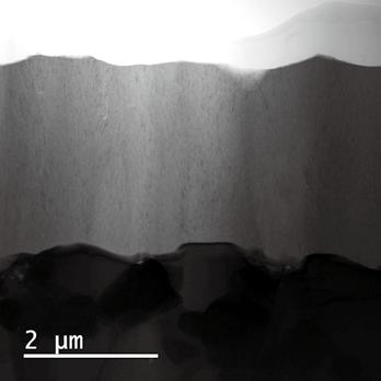
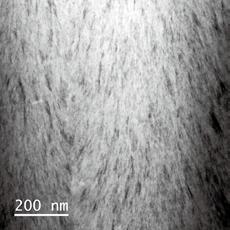
Higher hardness and more than the conventional wear resistance due to a fine crystal structure AlTiCrBN-based nano-layered coating
High Adhesion Strength
Significantly improved coating adhesion
More than twice the chipping resistance of conventional coatings
Special Surface Treatment
Suppresses thermal cracking by introducing high compressive stress
More than twice the chipping resistance as conventional coatings
Crystal Orientation Control Al2O3
By controlling the growth direction, Al2O3 is reinforced for crater wear resistance more than twice as good as conventional types
High Hardness TiCN
Increased TiCN hardness by using a C-rich composition for flank wear resistance more than twice as good as conventional types
Coating Layer
Carbide Substrate
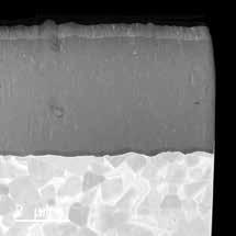
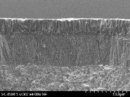
Cross Section of Cutting Edge Coating TEM Image
Comparison of Wear Resistance
Applicable Grade: ACS3000
Ultra-fine Grained B Additive
New AlTiBN coating, with an ultra-fine coating structure, achieves high strength and toughness
Outstanding chipping resistance and wear resistance
High Adhesion Strength
Significantly improved coating adhesion
More than twice the conventional chipping resistance
(Output: 156 holes)
(Output: 156 holes)
Work Material: S50C, Tool: GDXH200D5S25-06 (ø20, 5D) Insert: Peripheral Insert GDXT06T204P-G (ACP2000) Central Insert: GDXT06T206C-G (ACU2500) Cutting Conditions: Vc = 150m/min, f = 0.10mm/rev, H = 38mm (Through Hole), Internal Coolant Supply (Water-soluble)
Depending on the machining application or workpiece shape, set the cutting conditions with reference to the table below.
¢ Insert Selection Guide The GDX insert series has a variety of options
GDX series Recommended Cutting Conditions (2D/3D/4D)
S15C
S45C
S45C Hardened
S75C
S75C Hardened
SCM, SNCM
SCM, SNCM Hardened
SCM, SNCM Hardened
SCM, SNCM Hardened
SKD, SKT, SKH
SKD, SKT, SKH Hardened
SUS430 and Others (Martensitic/Ferritic)
SUS403 and Others (Martensitic/Hardened) SUS304, SUS316 (Austenitic)
S15C
S45C
S45C Hardened
S75C
S75C Hardened
SCM, SNCM
SCM, SNCM Hardened
SCM, SNCM Hardened
SCM, SNCM Hardened
SKD, SKT, SKH
SKD, SKT, SKH Hardened
SUS430 and Others (Martensitic/Ferritic)
SUS403 and Others (Martensitic/Hardened) SUS304, SUS316 (Austenitic)
SS400
S15C
S45C
S45C Hardened
S75C
S75C Hardened
SCM, SNCM
SCM, SNCM Hardened
SCM, SNCM Hardened
SCM, SNCM Hardened
SKD, SKT, SKH
SKD, SKT, SKH Hardened
SUS430 and Others (Martensitic/Ferritic)
SUS403 and Others (Martensitic/Hardened)
SUS304, SUS316 (Austenitic)
· The recommended conditions may not be practical depending on the operating conditions (e.g.
*Caution · The cutting conditions above are a
Steel, Carbon Steel
Low-alloy Steel
Steel
Stainless Steel
Cast Iron
Ductile Cast Iron
SS400
Steel, Carbon Steel
Low-alloy Steel
High-alloy Steel
Stainless Steel
Cast Iron
Ductile Cast Iron
SS400
Steel, Carbon Steel
Low-alloy Steel
High-alloy Steel
Stainless Steel
Cast Iron
Ductile Cast Iron
4D
GDX series Recommended Cutting Conditions (5D/6D/7D)
SS400
S15C
S45C
S45C Hardened
S75C
S75C Hardened
SCM, SNCM
SCM, SNCM Hardened
SCM, SNCM Hardened
SCM, SNCM Hardened
SKD, SKT, SKH
SKD, SKT, SKH Hardened
SUS430 and Others (Martensitic/Ferritic)
SUS403 and Others (Martensitic/Hardened)
SUS304, SUS316 (Austenitic)
SS400
S15C
S45C
S45C Hardened
S75C
S75C Hardened
Low-alloy Steel
SCM, SNCM
SCM, SNCM Hardened
SCM, SNCM Hardened
SCM, SNCM Hardened
SKD, SKT, SKH
SKD, SKT, SKH Hardened
SUS430 and Others (Martensitic/Ferritic)
SUS403 and Others (Martensitic/Hardened) SUS304, SUS316 (Austenitic)
Steel, Carbon Steel
SS400
S15C
S45C
S45C Hardened
S75C
S75C Hardened
Low-alloy Steel
SCM, SNCM
SCM, SNCM Hardened
SCM, SNCM Hardened
SCM, SNCM Hardened
High-alloy Steel
SKD, SKT, SKH
SKD, SKT, SKH Hardened
Stainless Steel
Cast Iron
SUS430 and Others (Martensitic/Ferritic)
SUS403 and Others (Martensitic/Hardened) SUS304, SUS316 (Austenitic)
Ductile Cast Iron
· The recommended conditions may not be practical depending on the
system). For 6D and 7D machining, reduce the feed to 75% of recommended conditions at engagement
entrance). Use the lower recommended limit feed at the exit of through holes (5mm from exit).
*Caution · The cutting conditions above are a guide. Actual conditions will need to be adjusted according to machine rigidity, work clamp rigidity, and other factors.
Cutting Conditions: Vc = 120m/min, f = 0.085mm/rev, H = 76mm (Through), Internal Coolant Supply (Water-soluble)
Realises stable drilling and doubled tool life compared to competitor’s products
Work Material: Nut (SS400)
Tool:
GDXH210D6S25-06 (ø21, 6D)
Insert: Peripheral Insert GDXT06T204P-L (ACU2500)
Central Insert: GDXT06T206C-L (ACU2500)
Cutting Conditions: Vc = 80m/min, f = 0.03 0.05mm/rev, H = 75mm x 2 (Flipped Drilling, Through), Internal Coolant Supply (Water-soluble)
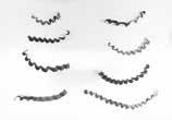
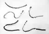
Realises stable drilling with short, divided chips compared to competitor’s products
Flipped drilling with deep hole drilling of H75mm from both ends
GDX series: Non-stop machining
Competitor’s product: Step machining (1mm)
Work Material: Flange (SS400)
Tool:
GDXH190D3S25-06 (ø19, 3D)
Insert: Peripheral Insert GDXT06T204P-L (ACU2500)
Central Insert: GDXT06T206C-L (ACU2500)
Cutting Conditions: Vc = 240m/min, f = 0.055mm/rev, H = 22mm (Through), Internal Coolant Supply (Water-soluble)
While the competitor’s product used step machining (1mm per step), the GDX series employed non-step machining and even so achieved thin, divided chips, realising high-efficiency, stable machining
GDX series
Competitor's Product B
3 times the e ciency
76mm/min Feed Rate (vf)
Work Material: Flange (S25C, S45C)
Tool:
GDXH200D3S25-06 (ø20, 3D)
Insert: Peripheral Insert GDXT06T204P-G (ACU2500)
Central Insert: GDXT06T206C-G (ACU2500)
Cutting Conditions: Vc = 180m/min, f = 0.08mm/rev, H = 38mm (Through), Internal Coolant Supply (Water-soluble)
Chip control was much improved from competitor’s product, achieving approx. 3 times the efficiency
Guidelines and Ratings
¢ Lathe Drilling Guidelines
Drill installation
· Set the drill so that the peripheral insert is parallel to the X-axis of the machine. (Fig 1) We also recommend mounting in an orientation such that the worker can see the peripheral insert. (although usage is possible even at 180° upside down)
Other notes
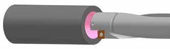
· When the drill is mounted on a lathe, the centre of the central insert is designed to be 0.1 to 0.2mm below the centre of the spindle.
· If the spindle deviates so far off centre that the centre of the central insert lies above the spindle centre, the central insert will break.
Also, if the centre falls more than a normal amount below the spindle centre, the pip at the bottom of the hole will grow larger (ø1mm or more) and wall precision will suffer. Take care accordingly.
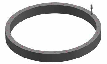
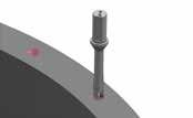
· Install a cover to prevent injury from possible chip fly-out (see disc-shaped chip in Figure 2) when through boring on a lathe.
If your lathe has no cover, attach a cover or similar part for your safety.
· Set the depth of cut for external turning or internal boring work to 20% or less of the drill diameter. (Ex.: For ø20.0mm, depth of cut 4mm or below)
Also, use a feed rate 30% to 70% lower than the recommended rate.
f=0.24mm/rev
f=0.12mm/rev
f=0.18mm/rev
f=0.06 mm/rev
Minimum Discharge Coolant Volume ( L /min)
Recommended Coolant Volume
<CAUTIONS>
D Power ratings are subject to change based on conditions such as work material and cutting speed, and should only be used for reference.
D Cutting Conditions (Reference) Work Material: S50C (230HB) Cutting Speed: Vc = 150m/min
<CAUTIONS>
D Coolant volume is a factor that affects drilling performance, particularly with respect to chip evacuation and lubricity. This is particularly important for chip evacuation and lubricity.
D Coolant pressure should be set higher for small drills. (Below ø18.0mm)
D Coolant volume is usually adjusted by changing the coolant pressure provided on most CNC machine tools.
D This table provides guideline values only. More coolant may be required depending on the machine, coolant and work material.
D Internal coolant supply is recommended. Dry machining and external coolant supply are not recommended, as chips will not be evacuated.
¢ Typical Power Ratings
¢ Typical Coolant Volume
Drill Diameter DC (mm)
Drill Diameter DC (mm)
Precautions and Troubleshooting
¢ Precautions for Attaching and Removing Inserts
· Before mounting the insert, remove all traces of foreign matter on the insert seat surface using air or other means.
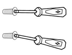
· When using the wrench, align it to the axis of the screw and press while turning. (Fig 3)
If the wrench is not aligned with the screw, the insert will be insufficiently clamped and the tip of the wrench and/or the torx hole of the screw may become deformed.
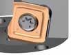
· Do not allow clearance between the insert seat and drill when mounting the insert. (Fig 4, A)
Figure 4 shows a properly attached insert.
* There is clearance to the outside of the central insert, which is normal, as the insert retaining surface is on the inside and back.
¢ Troubleshooting
Problem
Too much variation in hole diameter
Poor quality machined hole surface
Insert is broken
Phenomenon
Drilled hole diameter is larger than desired
Drilled hole diameter is smaller than desired
Significant difference in hole diameter at entrance and bottom
Poor machined surface from entrance to bottom of hole
Poor machined surface at bottom of hole
Scratches around hole exit
Return scratches are generated
Breakage on central insert (centre)
Fracture on peripheral insert
· Deflection of the holder due to high cutting force
· The cutting edge backs off and does not enter the workpiece
· Packing of chips
· High cutting force
· Low rigidity of workpiece
· Machined surfaces damaged by chips
Holder is vibrating during through cutting
Machining diameter is shrinking
Central insert centre is rising
· Insert is not strong enough
· High cutting load on cutting edge
Peripheral Insert Central Insert
Using a Wrench Insert Attachment
A A
· Decrease the feed speed to decrease cutting force
· When using the drill on a lathe, adjust by moving in the X-axis direction
· Increase the feed rate
· When using the drill on a lathe, adjust by moving in the X-axis direction
· Increase the feed rate to improve chip evacuation
· Use an L type chipbreaker for chip control
· Decrease cutting speed
· Review tooling to improve rigidity
· Increase the feed rate to improve chip evacuation
· Use an L type chipbreaker for chip control
· Drop cutting speed at hole exit to vc = 50m/min
· Drop feed rate at hole exit to 0.05mm/rev
· Increase feed rate
· Reconfirm and adjust centre height
· When using with a lathe, rotate the drill 180° to mount
· Decrease the feed rate to decrease cutting load
· Decrease the feed rate to decrease cutting load
Fig 3
Fig 4
SUMITOMO ELECTRIC Hartmetall GmbH
Konrad-Zuse-Straße 9 | 47877 Willich | Germany T +49 2154 4992-0 info@sumitomotool.com www.sumitomotool.com Scan and follow
SUMITOMO ELECTRIC Hardmetal Ltd. 2 Devon Way | Longbridge Technology Park Birmingham B31 2 TS | UK T +44 121 6613650 salesUK@sumitomotool.com