
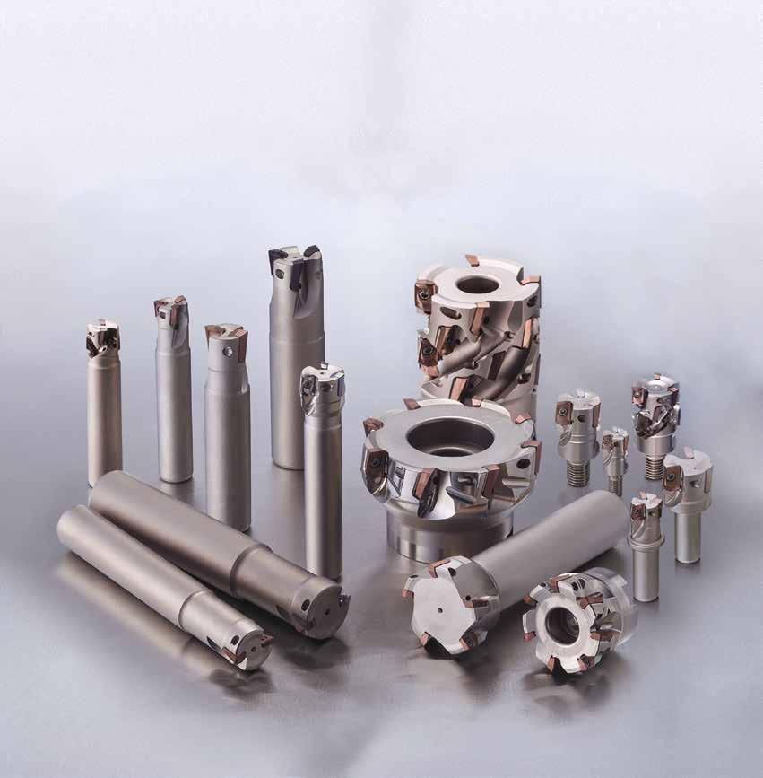
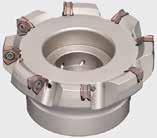
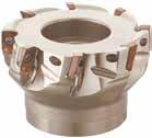
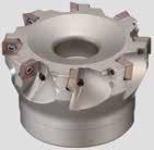
Supports Various Machining Operations
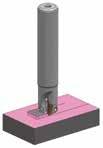
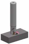
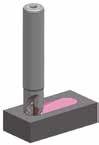
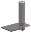
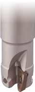
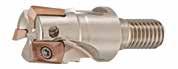
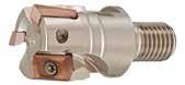
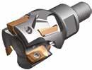
A lineup of cutter sizes from Ø 14 to Ø 160 mm, which enable large ramping angles, 28 repeater type items are now available in addition to the modular type and short shank type.
Excellent Machining Quality
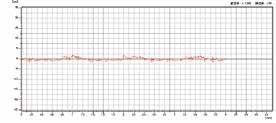
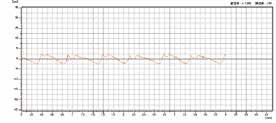
With a combination of optimised cutting edge shape and high-precision molding technology, superb wall surface accuracy and surface finish qualitiy are achieved.
Excellent Sharpness with Low Resistance
Reducing machining noise and suppressing burrs, the lineup includes ground type inserts with a focus on sharpness.
Applicable to Various Work Materials
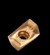
In addition to the general-purpose grade ACU2500, the new generation coated carbide grades XCU2500/XCK2000 are available. Applicable to various work materials such as steel, stainless steel, cast iron, exotic alloys and more.
Ø14Ø16Ø18Ø20Ø22Ø25Ø26Ø28Ø30Ø32Ø35Ø40Ø50Ø63Ø80Ø100Ø125Ø160
WEZ 11000RS 4, 65,76, 87, 109, 12
WEZ 11000R (Inch) 7, 109, 12
WEZ 17000RS 3, 43, 54, 64, 75, 86, 9, 118, 10 12
WEZ 17000R (Inch) 4, 75, 86, 9, 118, 10 12
WEZ 11000E12*22*, 3*32, 3*, 4*442, 3, 4, 5*52, 4, 65, 7810
WEZ 11000ES12*3*4*
WEZ 11000EL12*22*22*, 3222*, 32, 323
WEZ 17000E 2*232, 3*33, 43*, 5*4*, 6*7
WEZ 17000ES 2 3
WEZ 17000EL 2 222*, 322, 3, 43*, 5*4*, 6*
WEZ 11000M 222, 332, 3, 44, 54, 52, 4, 52, 3, 4, 52, 52, 4, 5, 6
WEZ 17000M 2, 322, 32, 3, 42, 32, 3, 4
Cat. No.
WEZ (Standard) * Different shank diameters in stock Suitable Applications
Range (mm) / No of Teeth
Ø20Ø25Ø30Ø32Ø35Ø40Ø50Ø63Ø80
WEZR 11000RS 4 4
WEZR 17000RS 2, 3, 43, 4, 55
WEZR 11000E1,22 22, 333, 4
WEZR 17000E 2,32,3
WEZR 11000M 3
WEZR 17000M 3



R0,2R0,4R0,5R0,8R1,0R1,2R1,6R2,0R2,4R3,0R3,2R4,0R5,0R6,4
AOMT11T3_ _ PEER-G lllllllllll
AOMT11T3_ _ PEER-H llll
AOET11T3_ _ PEER-F lllllllllll
AOET11T3_ _ PEER-P16 llllll
AOET11T3_ _ PEER-P20 llllll
AOET11T3_ _ PEER-P25 llllll
AOET11T3_ _ PEFR-S lllllllllll
AOMT1705_ _ PEER-L lll
AOMT1705_ _ PEER-G llllllllllllll
AOMT1705_ _ PEER-H ll
AOET1705_ _ PEER-F llllllllllllll
AOET1705_ _ PEER-P25 llllll
AOET1705_ _ PEER-P32 llllll
AOET1705_ _ PEFR-S llllllllllllll





Machine: Work Material: Tool:
Conditions: Vertical Machining Centre BT40, C50 WEZ 11020 E03 (Ø 20, 3 teeth)
AOMT11T308PEER-G (ACU2500) vc = 150 m/min, fz = 0,15 mm/t, ap = 8 mm, ae = 5 mm, dry
Features

Cutting Performance
Excellent Squareness
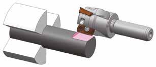
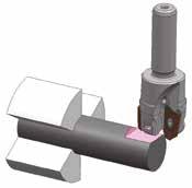
Developed for Multi-tasking Machines
Short shank type ideal for low-rigidity multi-tasking machines.
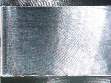
Superb Machining Quality
Shank design ideal for ER collets with face contact design that increases rigidity, realizing excellent shoulder accuracy and finished surface quality.
Supports various machining applications with a wide selection of chipbreakers, with sharp cutting edges, different nose radi and dedicated grades for specific work materials.


Machine:
Work Matarial: Tool: Insert:
Cutting Data:
Composite NC lathe
X5CrNiS1810, Ø 16 round bar
WEZ11020ES03-10 (Ø 20, 3 flutes)
AOET11T308PEER-F (ACU2500)
vc = 100 m/min, fz = 0,08 mm/t ap = 6 mm x 2 passes, ae = 2 mm, wet


Series High rigidity via face contact
Solid Carbide Endmills
Machine:
Work Matarial: Tool: Insert:
Cutting Data:
Composite NC lathe
X5CrNiS1810, Ø 16 round bar
WEZ11020ES03-10 (Ø 20, 3 flutes)
AOET11T308PEER-F (ACU2500)
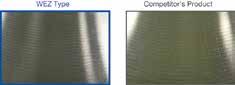
WEZ type: vc = 100 m/min, fz = 0,05 mm/t, ap = 2 mm, ae = 12 mm, wet
Competitor: vc = 100 m/min, fz = 0,05 mm/t, ap = 2 mm, ae = 6 mm x 2 passes, wet (solid carbide endmill)
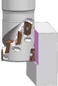
Larger tool diameter than carbide solid endmills enables reduced number of passes for high-efficiency machining.
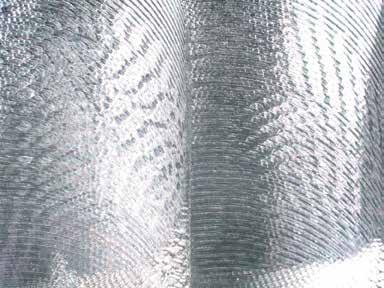
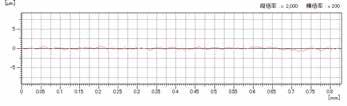
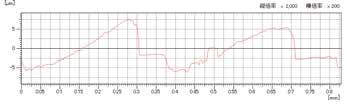
Good shoulder accuracy and machined surface quality, eliminating the finishing process.
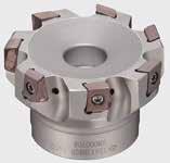
Ground insert High rake wave cutting edge


Number of corners


Ground Finish on Cutting Edge and Guide Face
The guide face has a ground finish as well as the cutting edge, minimizing corner difference when mounting on the body. Stable runout precision and machining qualitiy.
F Type
Cutting edge specialized for sharpness and machining accuracy

Sharpness from ground finish enables burr control.
Excellent squareness with all diameters.

Machine:
Work Material
Tool:
Insert:
Cutting Conditions:
Cutting edge flank Guide face

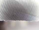
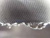
Vertical Machining Centre BT50, X5CrNiS18 9 WEZ 11050 RS07 (Ø 50, 7 teeth)
AOET11T308PEER-F (ACU2500) vc = 120 m/min, fz = 0,12
Chipbreaker for wall surface squareness equivalent to solid endmills

dry
Premium item with cutting edge shape optimised for each cutter diameter while maintaining the F type chipbreaker's sharpness.
Enables wall surface squareness equal to solid endmills through a blade shape optimised for each tool diameter.
P Type Chipbreaker Selection
Ø14Ø16Ø18Ø20Ø22Ø25Ø28Ø30Ø32Ø35 => Ø40
AOET11T3_ _PEER-P_ _ -P16-P20 – -P25 –
AOET1705_ _PEER-P_ _ – -P25-P32 –
Machine: Work Material: Tool: Insert: Cutting Conditions:


Vertical Machining Centre BT50, C50
WEZ 11020 E03 (Ø 20, 3 teeth)





AOET11T308PEER-P20 (ACU2500) vc = 150 m/min, fz = 0,1 mm/t, ap = 8 mm x 3 passes, ae = 1 mm, dry
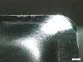
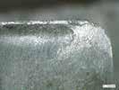
Sharp edge chipbreaker for non-ferrous metals, with excellent adhesion resistance

Suppresses adhesion with rake face lapping.
DLC coat inserts available for further improved adhesion resistance.

Machine:
Work Material: Tool: Insert:
Cutting Conditions:
Vertical Machining Centre BT50, AlSi12Cu
WEZ 11020 E03 (Ø 20, 3 teeth)
AOET11T308PEER-S (H20) vc = 350 m/min, fz = 0,1 mm/t, ap = 3
New generation coated carbide grades XCU2500/ XCK2000 now available. Enhanced lineup of coatings in addition to cemented carbide and cermet for milling steel, stainless steel, cast iron and aluminum alloy.
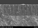
New Absotech TM (absolute technology) coating technology that realises absolute stability.

Special Surface Treatment
Suppresses thermal cracking by introducing high compressive stress, resulting in chipping resistance more than twice as good as conventional types
Crystal Orientation Control Al2O3 By controlling the growth direction, Al2O3 is reinforced for crater wear resistance more than twice as good as conventional types
High Hardness TiCN
Increased TiCN hardness by using a C-rich composition for flank wear resistance more than twice as good as conventional types.
Grades: ACP2000, ACK2000



New Super Multi-Layered Composition
Higher hardness and twice the conventional wear resistance due to a fine crystal structure
AlTiCrBN-based nano-layered coating.
High Adhesion Strength
Significantly improved coating adhesion. Chipping resistance more than twice as good as conventional types.
Grades: ACU2500, ACP3000, ACK3000
Pure cubic crystal AlTIN with high Al content
With proprietary structural control technology, differently composed layers of AlTIN are stacked at the nanometre level.

· For high-speed
of steel
With a high Al-compositioin containing over 80% Al on average, it also maintains a cubic crystalline structure to achieve excellent thermal resitance and high hardness.
Vastly improved wear resistance.
Special Surface Treatment
Proprietary surface treatment introduces high compressioin stress to the coating, suppressing the development of cracks.
Greatly improved fracture and thermal crack resistance.
Grades: XCU2500, XCK2000
· Stable long tool life in high-speed machining is realised by adopting a tough carbide substrate and a new coating with excellent thermal crack resistance
· General-purpose grade for a wide variety of materials such as steel, cast iron and stainless steel
· For machining high-hardness stainless steel
· Adopts newly developed high-strength cemented carbide substrate with excellent wear resistance and thermal resistance, realizing outstanding stability when machining hardened stainless steel
· New coating combining wear and fracture resistance realises long tool life in medium-speed to high-speed machining Super FF Coat
· For high-speed cast iron milling
· Stable long tool life in high-speed machining is realised by adopting a tough carbide substrate and a new coating with excellent thermal resistance
· For high-speed cast iron milling
· Along with a high-hardness carbide substrate, the new coating combining wear and fracture resistance realises superb long tool life in medium-speed to high-speed machining
· General-purpose grade supporting steel, stainless steel, and cast iron machining
· Adopts a carbide substrate with excellent fracture resistance and wear resistance, plus a new coating with excellent wear resistance and chipping resistance, realising stable long tool life with various work material grades
· Our 1st recommended grade for milling steel
· Carbide substrate with excellent thermal crack resistance, plus a new coating with excellent wear resistance and chipping resistance, realises stable long tool life over a wide range of cutting conditions (New) Super ZX Coat
· Our 1st recommended grade for milling stainless steel
· Adopts high-strength cemented carbide substrate and super multi-layered coating for next-level wear resistance and fracture resistance
· Our 1st recommended grade for milling cast iron
· Adopts a high thermal conductivity carbide substrate and a new coating with excellent wear resistance and chipping resistance, realizing stable long tool life over a wide range of cast iron machining operations
AURORA Coat (DLC)
· Grade for milling non-ferrous metal, utilising DLC coat with a low coefficient of friction and excellent adhesion resistance
WEZ11 Type
Cutter: Insert: Cutting Data:
Material
WEZ 11020 E03
AO_T11T3 type ap = 3 mm, ae = 10 mm, dry
<0, 15%C, annealed
Unalloyed steel, <0, 45%C, annealed , <0, 45%C, tempered , <0, 75%C, annealed , <0, 75%C, tempered annealed Low alloyed steel, tempered , tempered , tempered , High alloyed and tool steel, annealed , tempered
Stainless steel, ferritic/martensitic, annealed , martensitic, tempered , austenitic, plunged
Grey cast iron
Nodular cast iron
High tempered resist. alloys, Fe based, annealed , hardened
Aluminium alloy, Si < 12,6% , Si > 12,6%
Copper alloy
300
200
240
The above recommended cutting conditions are meant as a guide. Actual conditions will depend on the individual machine, work shape and clamping. They will need to be adjusted according to machine rigidity, work clamp rigidity, cutting depth and other factors.
For groove milling, reduce the feed rate approximately 70 % of the corresponding value shown above.
Cutter:
Insert:
Cutting Data: Min. -
WEZ 17032 E03
AO_T1705 type ap = 5 mm, ae = 16 mm, dry
Material
Feed Rate (mm/tooth) Cutting
<0, 15%C, annealed
Unalloyed steel, <0, 45%C, annealed , <0, 45%C, tempered , <0, 75%C, annealed , <0, 75%C, tempered , annealed Low alloyed steel, tempered tempered tempered ,
High alloyed and tool steel, annealed , tempered
Stainless steel, ferritic/martensitic, annealed , martensitic, tempered , austenitic, plunged
Grey cast iron
Nodular cast iron
High tempered resist. alloys, Fe based, annealed , hardened
Aluminium alloy, Si < 12,6% , Si > 12,6%
Copper alloy
300
180
275
300
350
200
200
240
The above recommended cutting conditions are meant as a guide. Actual conditions will depend on the individual machine, work shape and clamping. They will need to be adjusted according to machine rigidity, work clamp rigidity, cutting depth and other factors. For groove milling, reduce the feed rate approximately 70 % of the corresponding value shown above.
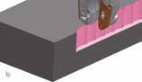
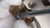
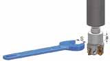
Clean the mounting seat and contact parts.
Apply screw lubrication to the screw thread as well as the screw head face to prevent seizure.
While pressing the insert solidly against the seat surface, tighten at the screws with the included wrench.
After tightening, check that there are no gaps between the surfaces.





Inserts are sold separately. Check the arbor mounting size (DCB) when selecting the cutter. * For securing the Ø 80 mm and Ø 100 mm cutter to the arbors, use JIS B1176 hexagonal bolt. (Ø 80 mm: M12x30 to 35 mm, Ø 100 mm: M16x40x45 mm)
Spare Parts Identification Details
WEZ11040RS04
11040RS06 11050RS05 11050RS07 11063RS06 11063RS08
11080R(S)07
11080R(S)10
BFTX0306IP1,5TRDR08IP
Recommended Cutting Conditions
*When mounting inserts with nose radius of ≥ 2,4 mm, modification of the body is required.
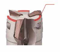
Modify this edge.
Reworking guidelines
Corner radius = 2,4 mm: C = 1 mm (AOMT11T324PEER)
Corner radius = 3,0 mm: C = 1 mm (AOMT11T330PEER)
Corner radius = 3,2 mm: C = 1 mm (AOMT11T332PEER) Standard: R = 1 mm
C: Chamfer R: Radius
High Speed / Light Cut
General Purpose
Roughing
AOMT11T302PEER-G llqllqllll 0,21
11T304PEER-G lmllmlllll 0,41 11T305PEER-G lqqqqllq 0,51 11T308PEER-G lmllmlllll 0,81
11T310PEER-G lqqqqllq 1,01 11T312PEER-G llqllqlllq 1,21
11T316PEER-G llqllqlll 1,61 11T320PEER-G llqllqlll 2,01 11T324PEER-G lqqqqll 2,41 11T330PEER-G llqllqlll 3,02 11T332PEER-G lqqqqll 3,22
AOMT11T304PEER-H lmllmllll 0,41
11T308PEER-H lmllmllll 0,81 11T312PEER-H lqqqqll 1,21 11T316PEER-H lqqqqll 1,61
AOET11T302PEER-F l – 0,21 11T304PEER-F l – 0,41 11T305PEER-F l – 0,51
11T308PEER-F l – 0,81
11T310PEER-F l – 1,01
11T312PEER-F l – 1,21
11T316PEER-F l – 1,61
11T320PEER-F l – 2,01
11T324PEER-F l – 2,41 11T330PEER-F l – 3,02 11T332PEER-F l – 3,22
AOET11T302PEFR-S ll – 0,21
11T304PEFR-S ll – 0,41
11T305PEFR-S ll – 0,51
11T308PEFR-S ll – 0,81
11T310PEFR-S ll – 1,01
11T312PEFR-S ll – 1,21
11T316PEFR-S ll – 1,61
11T320PEFR-S ll – 2,01
11T324PEFR-S ll – 2,41
11T330PEFR-S ll – 3,02
11T332PEFR-S ll – 3,22
L: Low cutting force
G: General purpose
H: Strong edge
F: Finishing
P: High-precision machining
S: Non ferrous metals

l 160100634016,49,02990
l 160100634016,49,02990
l 160100634016,49,02990
m *100706331,7512,78,03246271852,082 17100R08 m *100706331,7512,78,03246271882,072
1601006350,819,111,03872 105,094
Recommended Cutting Conditions
*When mounting inserts with nose radius of ≥ 2,4 mm, modification of the body is required.
Modify this edge.
Reworking guidelines
Corner
(AOMT170524PEER)
Corner radius = 3,0 mm: C = 1 mm (AOMT170530PEER)
Corner radius = 3,2 mm: C = 1 mm (AOMT170532PEER)
Corner radius = 4,0 mm: C = 2 mm (AOMT170540PEER)
Corner radius = 5,0 mm: C = 5 mm (AOMT170550PEER)
Corner radius = 6,4 mm: C = 5 mm (AOMT170564PEER)
Standard: R = 1 mm
C: Chamfer R: Radius
Carbide High Speed / Light Cut General Purpose Roughing
AOMT170502PEER-L l – q – qllq 0,21
170504PEER-L lm – lm – llll 0,41 170508PEER-L lm – lm – llll 0,81 170512PEER-L l – q – qll 1,21 170516PEER-L l – q – qll 1,61
AOMT170502PEER-G llqllqlllq 0,21
170504PEER-G lmllmlllll 0,41
170505PEER-G lqqqqllq 0,51 170508PEER-G lmllmlllll 0,81 170510PEER-G lqqqqllq 1,01 170512PEER-G llqllqlllq 1,21 170516PEER-G llqllqlll 1,61 170520PEER-G llqllqlll 2,01 170524PEER-G lqqqqll 2,41 170530PEER-G llqllqlll 3,01 170532PEER-G llqqlqlll 3,21 170540PEER-G llqllqlll 4,01 170550PEER-G llqllqlll 5,02 170564PEER-G lqqqqll 6,42
AOMT170504PEER-H lmllmllll 0,41 170508PEER-H lmllmllll 0,81 170512PEER-H lqqqqll 1,21 170516PEER-H lqlqqll 1,61
AOET170502PEER-F l – 0,21
170504PEER-F l – 0,41
170505PEER-F l – 0,51
170508PEER-F l – 0,81
170510PEER-F l – 1,01
170512PEER-F l – 1,21
170516PEER-F l – 1,61
170520PEER-F l – 2,01
170524PEER-F l – 2,41
170530PEER-F l – 3,01
170532PEER-F l – 3,21
170540PEER-F l – 4,01
170550PEER-F l – 5,02
170564PEER-F l – 6,42
AOET170502PEFR-S ll – 0,21
170504PEFR-S ll – 0,41
170505PEFR-S ll – 0,51
170508PEFR-S ll – 0,81
170510PEFR-S ll – 1,01
170512PEFR-S ll – 1,21
170516PEFR-S ll – 1,61
170520PEFR-S ll – 2,01
170524PEFR-S ll – 2,41
170530PEFR-S ll – 3,01
170532PEFR-S ll – 3,21
170540PEFR-S ll – 4,01
170550PEFR-S ll – 5,02
170564PEFR-S ll – 6,42
1
2
L: Low cutting force G: General purpose
H: Strong edge
F: Finishing
P: High-precision machining
S: Non ferrous metals
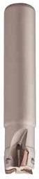
Body - WEZ (Shank Type)
Spare Parts
WEZ11014E01
Identification Details
*When mounting inserts with nose radius of ≥ 2,4 mm, modification of the body is required.
Modify this edge.
Reworking guidelines
Corner radius = 2,4 mm: C = 1 mm (AOMT11T324PEER)
Corner radius = 3,0 mm: C = 1 mm (AOMT11T330PEER)
Corner radius = 3,2 mm: C = 1 mm (AOMT11T332PEER)
Standard: R = 1 mm
C: Chamfer
Inserts
Application
High Speed / Light Cut
General Purpose
Roughing Cat. No.
Coated Carbide
AOMT11T302PEER-G llqllqllll 0,21
11T304PEER-G lmllmlllll 0,41
11T305PEER-G lqqqqllq 0,51
11T308PEER-G lmllmlllll 0,81
11T310PEER-G lqqqqllq 1,01 11T312PEER-G llqllqlllq 1,21
11T316PEER-G llqllqlll 1,61 11T320PEER-G llqllqlll 2,01 11T324PEER-G lqqqqll 2,41 11T330PEER-G llqllqlll 3,02 11T332PEER-G lqqqqll 3,22
AOMT11T304PEER-H lmllmllll 0,41
11T308PEER-H lmllmllll 0,81 11T312PEER-H lqqqqll 1,21 11T316PEER-H lqqqqll 1,61
AOET11T302PEER-F l – 0,21 11T304PEER-F l – 0,41
11T305PEER-F l – 0,51
11T308PEER-F l – 0,81 11T310PEER-F l – 1,01 11T312PEER-F l – 1,21
11T316PEER-F l – 1,61 11T320PEER-F l – 2,01
11T324PEER-F l – 2,41 11T330PEER-F l – 3,02 11T332PEER-F l – 3,22
AOET11T302PEER-P16 l – 0,21
11T304PEER-P16 l – 0,41
11T305PEER-P16 l – 0,51
11T308PEER-P16 l – 0,81
11T310PEER-P16 l – 1,01
11T312PEER-P16 l – 1,21
11T302PEER-P20 l – 0,21
11T304PEER-P20 l – 0,41
11T305PEER-P20 l – 0,51
11T308PEER-P20 l – 0,81
11T310PEER-P20 l – 1,01
11T312PEER-P20 l – 1,21
11T302PEER-P25 l – 0,21
11T304PEER-P25 l – 0,41
11T305PEER-P25 l – 0,51
11T308PEER-P25 l – 0,81
11T310PEER-P25 l – 1,01
11T312PEER-P25 l – 1,21
AOET11T302PEFR-S ll – 0,21
11T304PEFR-S ll – 0,41
11T305PEFR-S ll – 0,51
11T308PEFR-S ll – 0,81
11T310PEFR-S ll – 1,01
11T312PEFR-S ll – 1,21
11T316PEFR-S ll – 1,61
11T320PEFR-S ll – 2,01
11T324PEFR-S ll – 2,41
11T330PEFR-S ll – 3,02
11T332PEFR-S ll – 3,22
Recommended Cutting Conditions
L: Low cutting force
G: General purpose
H: Strong edge
F: Finishing
P: High-precision machining
S: Non ferrous metals
*P16 is applicable to cutter diameters Ø 14 mm and Ø 16 mm.
*P20 is applicable to cutter diameters Ø 18 mm, Ø 20 mm.
*P25 is applicable to cutter diameters Ø 25 mm, Ø 28 mm.
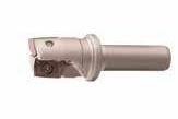
- WEZ (Short Shank Type)
DCDCSFMSDMMLHLULSLF
WEZ11014ES01-12 l 1418123027356510,051
11016ES02-10 l 1618102522305520,041 11016ES02-12 l 1618123027356520,051
11020ES03-10 l 20181025–305530,042
11020ES03-12 l 20181230–356530,062 11020ES03-16 l 2023163027407030,101 11025ES04-12 l 25231230–356540,092 11025ES04-16 l 25231630–407040,122
WEZ11014ES01-12 1,5TRDR08IP
11016ES02-10BFTX0305IP
11016ES02-12
11020ES03-10
11020ES03-12
11020ES03-16
11025ES04-12
11025ES04-16
BFTX0306IP
*When mounting inserts with nose radius of ≥ 2,4 mm, modification of
Modify this edge.
Reworking guidelines
Corner radius = 2,4 mm: C = 1 mm
(AOMT11T324PEER)
Corner radius = 3,0 mm: C = 1 mm
(AOMT11T330PEER)
Corner radius = 3,2 mm: C = 1 mm
(AOMT11T332PEER)
Standard: R = 1
C: Chamfer R: Radius
0,15 mm/t
Inserts
Application
High Speed / Light Cut General Purpose Roughing
Cat. No.
Coated Carbide
AOMT11T302PEER-G llqllqllll 0,21
11T304PEER-G lmllmlllll 0,41
11T305PEER-G lqqqqllq 0,51
11T308PEER-G lmllmlllll 0,81
11T310PEER-G lqqqqllq 1,01 11T312PEER-G llqllqlllq 1,21
11T316PEER-G llqllqlll 1,61 11T320PEER-G llqllqlll 2,01 11T324PEER-G lqqqqll 2,41 11T330PEER-G llqllqlll 3,02 11T332PEER-G lqqqqll 3,22
AOMT11T304PEER-H lmllmllll 0,41
11T308PEER-H lmllmllll 0,81 11T312PEER-H lqqqqll 1,21 11T316PEER-H lqqqqll 1,61
AOET11T302PEER-F l – 0,21 11T304PEER-F l – 0,41
11T305PEER-F l – 0,51
11T308PEER-F l – 0,81 11T310PEER-F l – 1,01 11T312PEER-F l – 1,21
11T316PEER-F l – 1,61 11T320PEER-F l – 2,01 11T324PEER-F l – 2,41 11T330PEER-F l – 3,02 11T332PEER-F l – 3,22
AOET11T302PEER-P16 l – 0,21
11T304PEER-P16 l – 0,41
11T305PEER-P16 l – 0,51
11T308PEER-P16 l – 0,81
11T310PEER-P16 l – 1,01
11T312PEER-P16 l – 1,21
11T302PEER-P20 l – 0,21
11T304PEER-P20 l – 0,41
11T305PEER-P20 l – 0,51
11T308PEER-P20 l – 0,81
11T310PEER-P20 l – 1,01
11T312PEER-P20 l – 1,21
11T302PEER-P25 l – 0,21
11T304PEER-P25 l – 0,41
11T305PEER-P25 l – 0,51
11T308PEER-P25 l – 0,81
11T310PEER-P25 l – 1,01
11T312PEER-P25 l – 1,21
AOET11T302PEFR-S ll – 0,21
11T304PEFR-S ll – 0,41
11T305PEFR-S ll – 0,51
11T308PEFR-S ll – 0,81
11T310PEFR-S ll – 1,01
11T312PEFR-S ll – 1,21
11T316PEFR-S ll – 1,61
11T320PEFR-S ll – 2,01
11T324PEFR-S ll – 2,41
11T330PEFR-S ll – 3,02
11T332PEFR-S ll – 3,22
L: Low cutting force
G: General purpose
H: Strong edge
F: Finishing
P: High-precision machining
S: Non ferrous metals
*P16 is applicable to cutter diameters Ø 14 mm and Ø 16 mm.
*P20 is applicable to cutter diameters Ø 18 mm, Ø 20 mm.
*P25 is applicable to cutter diameters Ø 25 mm, Ø 28 mm.
WEZ11014EL01
11016EL02(-14) 11018EL02
11020EL02(-18)
11025EL02(-22) 11025EL03
11028EL02 11030EL02
BFTX0306IP 11022EL02
11032EL02(-30) 11032EL03
11035EL02 11035EL03
11040EL02
11050EL03
BFTX0305IP 1,5TRDR08IP
*When mounting inserts with nose radius of ≥ 2,4 mm, modification of the body is required.
Modify this edge.
Reworking guidelines
Corner radius = 2,4 mm: C = 1 mm (AOMT11T324PEER)
Corner radius = 3,0 mm: C = 1 mm (AOMT11T330PEER)
Corner radius = 3,2 mm: C = 1 mm (AOMT11T332PEER)
Standard: R = 1 mm
C: Chamfer R: Radius
Inserts
Application
High Speed / Light Cut
General Purpose
Roughing
Cat. No.
Coated Carbide
AOMT11T302PEER-G llqllqllll 0,21
11T304PEER-G lmllmlllll 0,41
11T305PEER-G lqqqqllq 0,51
11T308PEER-G lmllmlllll 0,81
11T310PEER-G lqqqqllq 1,01 11T312PEER-G llqllqlllq 1,21
11T316PEER-G llqllqlll 1,61 11T320PEER-G llqllqlll 2,01 11T324PEER-G lqqqqll 2,41 11T330PEER-G llqllqlll 3,02 11T332PEER-G lqqqqll 3,22
AOMT11T304PEER-H lmllmllll 0,41
11T308PEER-H lmllmllll 0,81 11T312PEER-H lqqqqll 1,21 11T316PEER-H lqqqqll 1,61
AOET11T302PEER-F l – 0,21 11T304PEER-F l – 0,41
11T305PEER-F l – 0,51
11T308PEER-F l – 0,81 11T310PEER-F l – 1,01 11T312PEER-F l – 1,21
11T316PEER-F l – 1,61 11T320PEER-F l – 2,01 11T324PEER-F l – 2,41 11T330PEER-F l – 3,02 11T332PEER-F l – 3,22
AOET11T302PEER-P16 l – 0,21
11T304PEER-P16 l – 0,41
11T305PEER-P16 l – 0,51
11T308PEER-P16 l – 0,81
11T310PEER-P16 l – 1,01
11T312PEER-P16 l – 1,21
11T302PEER-P20 l – 0,21
11T304PEER-P20 l – 0,41
11T305PEER-P20 l – 0,51
11T308PEER-P20 l – 0,81
11T310PEER-P20 l – 1,01
11T312PEER-P20 l – 1,21
11T302PEER-P25 l – 0,21
11T304PEER-P25 l – 0,41
11T305PEER-P25 l – 0,51
11T308PEER-P25 l – 0,81
11T310PEER-P25 l – 1,01
11T312PEER-P25 l – 1,21
AOET11T302PEFR-S ll – 0,21
11T304PEFR-S ll – 0,41
11T305PEFR-S ll – 0,51
11T308PEFR-S ll – 0,81
11T310PEFR-S ll – 1,01
11T312PEFR-S ll – 1,21
11T316PEFR-S ll – 1,61
11T320PEFR-S ll – 2,01
11T324PEFR-S ll – 2,41
11T330PEFR-S ll – 3,02
11T332PEFR-S ll – 3,22
L: Low cutting force
G: General purpose
H: Strong edge
F: Finishing
P: High-precision machining
S: Non ferrous metals
*P16 is applicable to cutter diameters Ø 14 mm and Ø 16 mm.
*P20 is applicable to cutter diameters Ø 18 mm, Ø 20 mm.
*P25 is applicable to cutter diameters Ø 25 mm, Ø 28 mm.
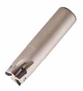
Body
Applicable Cutters Inserts are sold separately. Spare Parts Identification Details
WEZ17025E02(-20)
17028E02
17030E03
17032E02
17032E03(-25)
17035E03
17040E03
17040E04
17050E03(-42)
17050E05(-42)
17063E04(-42)
17063E06(-42)
17080E07
BFTX0407IP 3,0TRDR15IP
BFTX0409IP
Recommended Cutting Conditions
*When mounting inserts with nose radius of ≥ 2,4 mm, modification of the body is required.
Modify this edge.
Reworking guidelines
Corner radius = 2,4 mm: C = 1 mm (AOMT170524PEER)
Corner radius = 3,0 mm: C = 1 mm (AOMT170530PEER)
Corner radius = 3,2 mm: C = 1 mm (AOMT170532PEER)
Corner radius = 4,0 mm: C = 2 mm (AOMT170540PEER)
Corner radius = 5,0 mm: C = 5 mm (AOMT170550PEER)
Corner radius = 6,4 mm: C = 5 mm (AOMT170564PEER)
Standard: R = 1 mm
C: Chamfer R: Radius
AOMT170502PEER-L l – q – qllq 0,21
170504PEER-L lm – lm – llll 0,41
170508PEER-L lm – lm – llll 0,81 170512PEER-L l – q – qll 1,21 170516PEER-L l – q – qll 1,61
AOMT170502PEER-G llqllqlllq 0,21
170504PEER-G lmllmlllll 0,41
170505PEER-G lqqqqllq 0,51 170508PEER-G lmllmlllll 0,81 170510PEER-G lqqqqllq 1,01 170512PEER-G llqllqlllq 1,21 170516PEER-G llqllqlll 1,61 170520PEER-G llqllqlll 2,01 170524PEER-G lqqqqll 2,41 170530PEER-G llqllqlll 3,01 170532PEER-G llqqlqlll 3,21 170540PEER-G llqllqlll 4,01 170550PEER-G llqllqlll 5,02 170564PEER-G qqqqqll 6,42
AOMT170504PEER-H lmllmllll 0,41 170508PEER-H lmllmllll 0,81 170512PEER-H lqqqqll 1,21 170516PEER-H lqlqqll 1,61
AOET170502PEER-F l – 0,21
170504PEER-F l – 0,41
170505PEER-F l – 0,51
170508PEER-F l – 0,81
170510PEER-F l – 1,01
170512PEER-F l – 1,21
170516PEER-F l – 1,61
170520PEER-F l – 2,01
170524PEER-F l – 2,41
170530PEER-F l – 3,01
170532PEER-F l – 3,21
170540PEER-F l – 4,01 170550PEER-F l – 5,02 170564PEER-F l – 6,42
AOET170502PEER-P25 l – 0,21
170504PEER-P25 l – 0,41
170505PEER-P25 l – 0,51
170508PEER-P25 l – 0,81
170510PEER-P25 l – 1,01
170512PEER-P25 l – 1,21
170502PEER-P32 l – 0,21
170504PEER-P32 l – 0,41
170505PEER-P32 l – 0,51
170508PEER-P32 l – 0,81
170510PEER-P32 l – 1,01
170512PEER-P32 l – 1,21
AOET170502PEFR-S ll – 0,21
170504PEFR-S ll – 0,41
170505PEFR-S
170520PEFR-S
Spare Parts
Applicable Cutters
BFTX0409IP
*When mounting inserts with nose radius of ≥ 2,4 mm, modification of the
Modify this edge.
Reworking guidelines
Corner radius = 2,4 mm: C = 1 mm (AOMT170524PEER)
Corner radius = 3,0 mm: C = 1 mm (AOMT170530PEER)
Corner radius = 3,2 mm: C = 1 mm (AOMT170532PEER)
Corner radius = 4,0 mm: C = 2 mm (AOMT170540PEER)
Corner radius = 5,0 mm: C = 5
(AOMT170550PEER)
Corner radius = 6,4 mm: C = 5 mm (AOMT170564PEER) Standard: R = 1 mm
C: Chamfer R: Radius
AOMT170502PEER-L l – q – qllq 0,21
170504PEER-L lm – lm – llll 0,41
170508PEER-L lm – lm – llll 0,81 170512PEER-L l – q – qll 1,21 170516PEER-L l – q – qll 1,61
AOMT170502PEER-G llqllqlllq 0,21
170504PEER-G lmllmlllll 0,41
170505PEER-G lqqqqllq 0,51 170508PEER-G lmllmlllll 0,81 170510PEER-G lqqqqllq 1,01 170512PEER-G llqllqlllq 1,21 170516PEER-G llqllqlll 1,61 170520PEER-G llqllqlll 2,01 170524PEER-G lqqqqll 2,41 170530PEER-G llqllqlll 3,01 170532PEER-G llqqlqlll 3,21 170540PEER-G llqllqlll 4,01 170550PEER-G llqllqlll 5,02 170564PEER-G qqqqqll 6,42
AOMT170504PEER-H lmllmllll 0,41 170508PEER-H lmllmllll 0,81 170512PEER-H lqqqqll 1,21 170516PEER-H lqlqqll 1,61
AOET170502PEER-F l – 0,21
170504PEER-F l – 0,41
170505PEER-F l – 0,51
170508PEER-F l – 0,81
170510PEER-F l – 1,01
170512PEER-F l – 1,21
170516PEER-F l – 1,61
170520PEER-F l – 2,01
170524PEER-F l – 2,41
170530PEER-F l – 3,01
170532PEER-F l – 3,21
170540PEER-F l – 4,01 170550PEER-F l – 5,02 170564PEER-F l – 6,42
AOET170502PEER-P25 l – 0,21
170504PEER-P25 l – 0,41
170505PEER-P25 l – 0,51
170508PEER-P25 l – 0,81
170510PEER-P25 l – 1,01
170512PEER-P25 l – 1,21
170502PEER-P32 l – 0,21
170504PEER-P32 l – 0,41
170505PEER-P32 l – 0,51
170508PEER-P32 l – 0,81
170510PEER-P32 l – 1,01
170512PEER-P32 l – 1,21
AOET170502PEFR-S ll – 0,21
170504PEFR-S ll – 0,41
170505PEFR-S
Spare Parts Identification Details
Insert Screw Wrench
Applicable Cutters
WEZ17025EL02
17028EL02
17030EL02
17032EL02(-30)
17032EL03
17035EL02
17040EL02
17040EL03
17040EL04
17050EL03(-42)
17050EL05(-42)
17063EL04(-42)
17063EL06(-42)
BFTX0407IP 3,0TRDR15IP
BFTX0409IP
Recommended Cutting Conditions
*When mounting inserts with nose radius of ≥ 2,4 mm, modification of the body is required.
Modify this edge.
Reworking guidelines
Corner radius = 2,4 mm: C = 1 mm (AOMT170524PEER)
Corner radius = 3,0 mm: C = 1 mm (AOMT170530PEER)
Corner radius = 3,2 mm: C = 1 mm (AOMT170532PEER)
Corner radius = 4,0 mm: C = 2 mm (AOMT170540PEER)
Corner radius = 5,0 mm: C = 5 mm (AOMT170550PEER)
Corner radius = 6,4 mm: C = 5 mm (AOMT170564PEER) Standard: R = 1 mm
C: Chamfer R: Radius
AOMT170502PEER-L l – q – qllq 0,21
170504PEER-L lm – lm – llll 0,41
170508PEER-L lm – lm – llll 0,81 170512PEER-L l – q – qll 1,21 170516PEER-L l – q – qll 1,61
AOMT170502PEER-G llqllqlllq 0,21
170504PEER-G lmllmlllll 0,41
170505PEER-G lqqqqllq 0,51 170508PEER-G lmllmlllll 0,81 170510PEER-G lqqqqllq 1,01 170512PEER-G llqllqlllq 1,21 170516PEER-G llqllqlll 1,61 170520PEER-G llqllqlll 2,01 170524PEER-G lqqqqll 2,41 170530PEER-G llqllqlll 3,01 170532PEER-G llqqlqlll 3,21 170540PEER-G llqllqlll 4,01 170550PEER-G llqllqlll 5,02 170564PEER-G qqqqqll 6,42
AOMT170504PEER-H lmllmllll 0,41 170508PEER-H lmllmllll 0,81 170512PEER-H lqqqqll 1,21 170516PEER-H lqlqqll 1,61
AOET170502PEER-F l – 0,21
170504PEER-F l – 0,41
170505PEER-F l – 0,51
170508PEER-F l – 0,81
170510PEER-F l – 1,01
170512PEER-F l – 1,21
170516PEER-F l – 1,61
170520PEER-F l – 2,01
170524PEER-F l – 2,41
170530PEER-F l – 3,01
170532PEER-F l – 3,21
170540PEER-F l – 4,01 170550PEER-F l – 5,02 170564PEER-F l – 6,42
AOET170502PEER-P25 l – 0,21
170504PEER-P25 l – 0,41
170505PEER-P25 l – 0,51
170508PEER-P25 l – 0,81
170510PEER-P25 l – 1,01
170512PEER-P25 l – 1,21
170502PEER-P32 l – 0,21
170504PEER-P32 l – 0,41
170505PEER-P32 l – 0,51
170508PEER-P32 l – 0,81
170510PEER-P32 l – 1,01
170512PEER-P32 l – 1,21
AOET170502PEFR-S ll – 0,21
170504PEFR-S ll – 0,41
170505PEFR-S
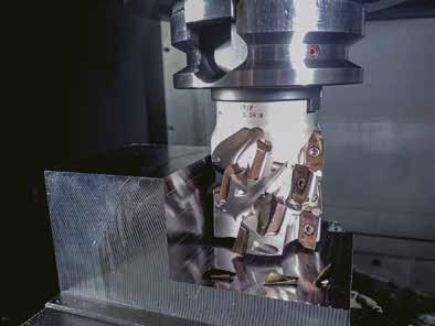
Body Features
Features
High-efficiency Shoulder Milling
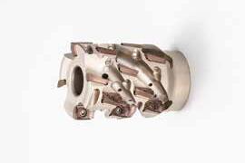
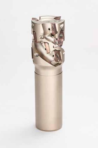
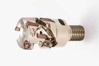
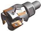
Inserts for "WaveMill" WEZ type are arranged in multiple stages forming a long cutting edge, to enable high-efficiency shoulder milling of deep steps.
Very Low Vibration Tendency
Sharp milling inserts and irregular pitched body help to reduce chatter marks caused by vibration.
Support for all Types of Work Materials
A lineup of grades specific to each work materials, as well as the general-purpose ACU2500 grade, which is applicable to steel, stainless steel and cast iron.
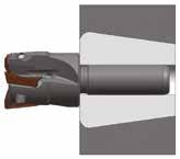
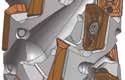
Improved Flute Shape Irregular Pitched Body
Optimised, upward tapering chip pocket geometry for improved chip removal and increased rigidity of the cutter body.
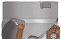
Cutting Performance
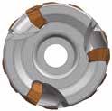
Irregular pitched body reduces vibration tendency
Significantly less vibrations are a result of the combination of sharp inserts and irregular tooth pitch.
Capable of stable machining even with BT40 spindle machines
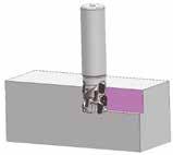
Capable of stable
even with a
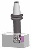
Competitor A
Machine:
Work Material: Tool: Insert: Cutting Conditions:
Vertical Machining Centre BT40, C55, overhang amount 60 mm
WEZR 11032E3632Z03 (Ø 32, 3 teeth, 4-stage)
AOET11T308PEER-G (ACU2500) vc = 150 m/min, fz = 0,1
B
Machine:
Work Material: Tool: Insert:
Cutting Conditions:
Vertical Machining Centre BT50, 42CrMo4
WEZR 17063RS5727Z04 (Ø 63, 4 teeth, 4-stage)
AOET170508PEER-G (ACU2500)
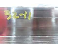
Optimised cutting edge shape and high-precision molding technology result in excellent shoulder accuracy.
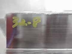
Machine:
Work Material: Tool: Insert:
Cutting Conditions:
Vertical Machining Centre BT50, C55, overhang amount 60 mm WEZR 11032E3632Z02 (Ø 32, 2 teeth, 4-stage)
AOET11T308PEER-G (ACU2500) vc = 160 m/min, fz = 0,15
Application Range
Steel, stainless steel, cast iron Aluminum alloys, titanium alloys
Note:
The depth of cut figures above are guidelines for use with BT50 machine tools. Use a depth of cut of approximately 50% if using BT40. For a tool overhang of L/D = 3 or L/D = 4, use a depth of cut of approximately 50% or 25%, respectively. There may be cases where machining cannot be performed at the depth of cut figures above, depending on the machine rigidity and work rigidity Cutting speed and feed rate data you will find on the next pages,
Take note of the
Radial Axial Rake Angle
1
11 040 R S 44 16 Z04
Note:
The cutting conditions above are a guide. Actual conditions will need to be adjusted according to machine rigidity, work clamp rigidity, depth of cut and other factors. There may be cases where machining cannot be performed under recommended cutting conditions, depending on the machine rigidity and work rigidity.
*When mounting inserts with nose radius of ≥ 2,4 mm, modification of the body is required.
Modify this edge.
Reworking guidelines
Corner radius = 2,4 mm: C = 1 mm (AOMT11T324PEER)
Corner radius = 3,0 mm: C = 1 mm (AOMT11T330PEER)
Corner radius = 3,2 mm: C = 1 mm (AOMT11T332PEER)
Standard: R = 1 mm
C: Chamfer R: Radius
High Speed / Light Cut
General Purpose
Roughing
AOMT11T302PEER-G llqllqllll 0,21
11T304PEER-G lmllmlllll 0,41 11T305PEER-G lqqqqllq 0,51
11T308PEER-G lmllmlllll 0,81 11T310PEER-G lqqqqllq 1,01 11T312PEER-G llqllqlllq 1,21
11T316PEER-G llqllqlll 1,61 11T320PEER-G llqllqlll 2,01 11T324PEER-G lqqqqll 2,41 11T330PEER-G llqllqlll 3,02 11T332PEER-G lqqqqll 3,22
AOMT11T304PEER-H lmllmllll 0,41
11T308PEER-H lmllmllll 0,81 11T312PEER-H lqqqqll 1,21 11T316PEER-H lqqqqll 1,61
AOET11T302PEER-F l – 0,21 11T304PEER-F l – 0,41
11T305PEER-F l – 0,51 11T308PEER-F l – 0,81
11T310PEER-F l – 1,01
11T312PEER-F l – 1,21
11T316PEER-F l – 1,61
11T320PEER-F l – 2,01
11T324PEER-F l – 2,41
11T330PEER-F l – 3,02
11T332PEER-F l – 3,22
AOET11T302PEFR-S
ll – 0,21
11T304PEFR-S ll – 0,41
11T305PEFR-S ll – 0,51
11T308PEFR-S ll – 0,81
11T310PEFR-S ll – 1,01
11T312PEFR-S ll – 1,21
11T316PEFR-S ll – 1,61
11T320PEFR-S ll – 2,01
11T324PEFR-S ll – 2,41
11T330PEFR-S ll – 3,02
11T332PEFR-S ll – 3,22
L: Low cutting force G: General purpose
H: Strong edge
F: Finishing
P: High-precision machining
S: Non ferrous metals
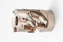
Body -
Take note of the cutter mounting size (DCB) when selecting a cutter. Inserts are sold seperately.
Note: The cutting conditions above are a guide. Actual conditions will need to be adjusted according to machine rigidity, work clamp rigidity, depth of cut and other factors. There may be cases where machining cannot be performed under recommended cutting conditions, depending on the machine rigidity and work rigidity.
*When mounting inserts with nose radius of ≥ 2,4 mm, modification of the body is required.
C: Chamfer R: Radius Radial Axial Rake Angle
Modify this edge.
Reworking guidelines
Corner radius = 2,4 mm: C = 1 mm (AOMT170524PEER)
Corner radius = 3,0 mm: C = 1 mm (AOMT170530PEER)
Corner radius = 3,2 mm: C = 1 mm (AOMT170532PEER)
Corner radius = 4,0 mm: C = 2 mm (AOMT170540PEER)
Corner radius = 5,0 mm: C = 5 mm (AOMT170550PEER)
Corner radius = 6,4 mm: C = 5 mm (AOMT170564PEER)
Standard: R = 1 mm
Inserts
Application Coated Carbide
High Speed / Light Cut
General Purpose
Roughing
AOMT170502PEER-L l – q – qllq 0,21
170504PEER-L lm – lm – llll 0,41
170508PEER-L lm – lm – llll 0,81 170512PEER-L l – q – qll 1,21 170516PEER-L l – q – qll 1,61
AOMT170502PEER-G llqllqlllq 0,21
170504PEER-G lmllmlllll 0,41
170505PEER-G lqqqqllq 0,51
170508PEER-G lmllmlllll 0,81 170510PEER-G lqqqqllq 1,01 170512PEER-G llqllqlllq 1,21 170516PEER-G llqllqlll 1,61 170520PEER-G llqllqlll 2,01 170524PEER-G lqqqqll 2,41 170530PEER-G llqllqlll 3,01 170532PEER-G llqqlqlll 3,21 170540PEER-G llqllqlll 4,01 170550PEER-G llqllqlll 5,02 170564PEER-G lqqqqll 6,42
AOMT170504PEER-H lmllmllll 0,41 170508PEER-H lmllmllll 0,81 170512PEER-H lqqqqll 1,21 170516PEER-H lqlqqll 1,61
AOET170502PEER-F l – 0,21
170504PEER-F l – 0,41
170505PEER-F l – 0,51
170508PEER-F l – 0,81
170510PEER-F l – 1,01
170512PEER-F l – 1,21
170516PEER-F l – 1,61
170520PEER-F l – 2,01
170524PEER-F l – 2,41
170530PEER-F l – 3,01
170532PEER-F l – 3,21
170540PEER-F l – 4,01
170550PEER-F l – 5,02
170564PEER-F l – 6,42
AOET170502PEFR-S ll – 0,21
170504PEFR-S ll – 0,41
170505PEFR-S ll – 0,51
170508PEFR-S ll – 0,81
170510PEFR-S ll – 1,01
170512PEFR-S ll – 1,21
170516PEFR-S ll – 1,61
170520PEFR-S ll – 2,01
170524PEFR-S ll – 2,41
170530PEFR-S ll – 3,01
170532PEFR-S ll – 3,21
170540PEFR-S ll – 4,01
170550PEFR-S ll – 5,02 170564PEFR-S ll – 6,42
L: Low cutting force
G: General purpose
H: Strong edge
F: Finishing
P: High-precision machining
S: Non ferrous metals
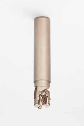
WEZR11020E1920Z02 m 20192030 110 4220,221 11020E3620Z01 m 203620451254410,241 11025E2725Z02 m 252725401306320,411 11025E3625Z02 m 253625501408420,421 11030E5325Z02 m 3053256515512620,522
m 3253327016012620,901
m 3553326515518630,882 11040E4432Z03 m 4044326015015530,872 11040E4432Z04 m 4044326015020540,852 11040E6132Z03 m 4061327516521730,952
WEZR11_ _ _ BFTX0306IP 1,5 TRDR08IP
WEZR 11 032 E 36 32 Z02
*When mounting inserts with nose radius of ≥ 2,4 mm, modification of the body is required.
C: Chamfer R: Radius Radial Axial Rake Angle
Modify this edge.
Reworking guidelines
Corner radius = 2,4 mm: C = 1 mm (AOMT11T324PEER)
Corner radius = 3,0 mm: C = 1 mm (AOMT11T330PEER)
Corner radius = 3,2 mm: C = 1 mm (AOMT11T332PEER)
Standard: R = 1 mm
Application
High Speed / Light Cut General Purpose
Roughing Cat. No.
Coated Carbide
Dimensions (mm)
AOMT11T302PEER-G llqllqllll 0,21
11T304PEER-G lmllmlllll 0,41
11T305PEER-G lqqqqllq 0,51
11T308PEER-G lmllmlllll 0,81
11T310PEER-G lqqqqllq 1,01
11T312PEER-G llqllqlllq 1,21
11T316PEER-G llqllqlll 1,61
11T320PEER-G llqllqlll 2,01 11T324PEER-G lqqqqll 2,41 11T330PEER-G llqllqlll 3,02 11T332PEER-G lqqqqll 3,22
AOMT11T304PEER-H lmllmllll 0,41
11T308PEER-H lmllmllll 0,81 11T312PEER-H lqqqqll 1,21 11T316PEER-H lqqqqll 1,61
AOET11T302PEER-F l – 0,21
11T304PEER-F l – 0,41
11T305PEER-F l – 0,51
11T308PEER-F l – 0,81
11T310PEER-F l – 1,01 11T312PEER-F l – 1,21
11T316PEER-F l – 1,61 11T320PEER-F l – 2,01 11T324PEER-F l – 2,41
11T330PEER-F l – 3,02 11T332PEER-F l – 3,22
AOET11T302PEER-P20 l – 0,21
11T304PEER-P20 l – 0,41
11T305PEER-P20 l – 0,51
11T308PEER-P20 l – 0,81
11T310PEER-P20 l – 1,01
11T312PEER-P20 l – 1,21
11T302PEER-P25 l – 0,21
11T304PEER-P25 l – 0,41
11T305PEER-P25 l – 0,51
11T308PEER-P25 l – 0,81
11T310PEER-P25 l – 1,01
11T312PEER-P25 l – 1,21
AOET11T302PEFR-S ll – 0,21
11T304PEFR-S ll – 0,41
11T305PEFR-S ll – 0,51
11T308PEFR-S ll – 0,81
11T310PEFR-S ll – 1,01
11T312PEFR-S ll – 1,21
11T316PEFR-S ll – 1,61
11T320PEFR-S ll – 2,01
11T324PEFR-S ll – 2,41
11T330PEFR-S ll – 3,02
11T332PEFR-S ll – 3,22
1
Fig. 2
L: Low cutting force
G: General purpose
H: Strong edge
F: Finishing
P: High-precision machining
S: Non ferrous metals
*P20 is applicable to cutter diameters Ø 18 mm, Ø 20 mm.
*P25 is applicable to cutter diameters Ø 25 mm, Ø 28 mm.
Use peripheral inserts with RE ≤ 0,8 mm from the second step and above.
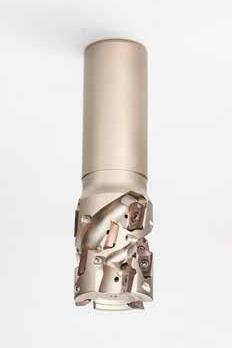
Body - WEZR (Shank Type)
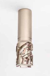
m 5057427513012431,581 17050E8442Z02 m 50844210514012621,041
Spare Parts
WEZR17_ _ _ BFTX0409IP 3,0 TRDR15IP WEZR 17 040 E 29 32 Z03
Note: The cutting conditions above are a guide. Actual conditions will need to be adjusted according to machine rigidity, work clamp rigidity, depth of cut and other factors. There may be cases where machining cannot be performed under recommended cutting conditions, depending on the machine rigidity and work rigidity.
*When mounting inserts with nose radius of ≥ 2,4 mm, modification of the body is required.
Modify this edge.
Reworking guidelines
Corner radius = 2,4 mm: C = 1 mm (AOMT170524PEER)
Corner radius = 3,0 mm: C = 1 mm (AOMT170530PEER)
Corner radius = 3,2 mm: C = 1 mm (AOMT170532PEER)
Corner radius = 4,0 mm: C = 2 mm (AOMT170540PEER)
Corner radius = 5,0 mm: C = 5 mm (AOMT170550PEER)
Corner radius = 6,4 mm: C = 5 mm (AOMT170564PEER)
Standard: R = 1 mm
C: Chamfer R: Radius
Inserts
Application
High Speed / Light Cut
General Purpose
Roughing
Coated Carbide
AOMT170502PEER-L l – q – qllq 0,21
170504PEER-L lm – lm – llll 0,41
170508PEER-L lm – lm – llll 0,81
170512PEER-L l – q – qll 1,21 170516PEER-L l – q – qll 1,61
AOMT170502PEER-G llqllqlllq 0,21
170504PEER-G lmllmlllll 0,41
170505PEER-G lqqqqllq 0,51
170508PEER-G lmllmlllll 0,81 170510PEER-G lqqqqllq 1,01
170512PEER-G llqllqlllq 1,21 170516PEER-G llqllqlll 1,61
170520PEER-G llqllqlll 2,01 170524PEER-G lqqqqll 2,41 170530PEER-G llqllqlll 3,01 170532PEER-G llqqlqlll 3,21 170540PEER-G llqllqlll 4,01 170550PEER-G llqllqlll 5,02
170564PEER-G qqqqqll 6,42
AOMT170504PEER-H lmllmllll 0,41
170508PEER-H lmllmllll 0,81 170512PEER-H lqqqqll 1,21
170516PEER-H lqlqqll 1,61
AOET170502PEER-F l – 0,21
170504PEER-F l – 0,41
170505PEER-F l – 0,51
170508PEER-F l – 0,81
170510PEER-F l – 1,01
170512PEER-F l – 1,21
170516PEER-F l – 1,61
170520PEER-F l – 2,01
170524PEER-F l – 2,41
170530PEER-F l – 3,01
170532PEER-F l – 3,21
170540PEER-F l – 4,01
170550PEER-F l – 5,02
170564PEER-F l – 6,42
AOET170502PEFR-S ll – 0,21
170504PEFR-S ll – 0,41
170505PEFR-S ll – 0,51
170508PEFR-S ll – 0,81
170510PEFR-S ll – 1,01
170512PEFR-S ll – 1,21
170516PEFR-S ll – 1,61
170520PEFR-S ll – 2,01
170524PEFR-S ll – 2,41
170530PEFR-S ll – 3,01
170532PEFR-S ll – 3,21
170540PEFR-S ll – 4,01
170550PEFR-S ll – 5,02
170564PEFR-S ll – 6,42
1
Fig. 2
L: Low cutting force
G: General purpose
H: Strong edge
F: Finishing
P: High-precision machining
S: Non ferrous metals
Use peripheral inserts with RE ≤ 0,8 mm from the second step and above.
WEZ11016M08Z2 l 168,5M84225581320,031 11018M08Z2 l 188,5M84225581320,031 11020M10Z2 l 2010,5M104930581520,061 11020M10Z3 l 2010,5M104930581530,051 11022M10Z3 l 2210,5M104930581530,061 11025M12Z2 l 2512,5M1256355101920,111 11025M12Z3 l 2512,5M1256355101930,101 11025M12Z4 l 2512,5M1256355101940,101 11026M12Z4 l 2612,5M1256355101940,101 11026M12Z5 l 2612,5M1256355101950,091 11028M12Z4 l 2812,5M1256355101940,111 11028M12Z5 l 2812,5M1256355101950,101 11030M16Z2 l 3017M1663405102420,201 11030M16Z4 l 3017M1663405102440,191 11030M16Z5 l 3017M1663405102450,171 11032M16Z2 l 3217M1663405102420,221 11032M16Z3 l 3217M1663405102430,201 11032M16Z4 l 3217M1663405102440,201
11032M16Z5 l 3217M1663405102450,191
11035M16Z2 l 3517M1663405102420,241
11035M16Z5 l 3517M1663405102450,221
11040M16Z2 l 4017M1663405102420,281 11040M16Z4 l 4017M1663405102440,261 11040M16Z5 l 4017M1663405102450,261 11040M16Z6 l 4017M1663405102460,251
Spare Parts
1 Insert Screw Wrench Applicable Cutters
WEZ11016M08Z2 BFTX0305IP 1,5TRDR08IP 11018M08Z2 11020M10Z2–11040M16Z2 BFTX0306IP
*When mounting inserts with nose radius of ≥ 2,4 mm, modification of the body is required.
Modify this edge.
Reworking guidelines
Corner radius = 2,4 mm: C = 1 mm (AOMT11T324PEER)
Corner radius = 3,0 mm: C = 1 mm (AOMT11T330PEER)
Corner radius = 3,2 mm: C = 1 mm (AOMT11T332PEER)
Standard: R = 1 mm
C: Chamfer R: Radius
Application Coated Carbide
High Speed / Light Cut
General Purpose
Roughing
AOMT11T302PEER-G llqllqllll 0,21
11T304PEER-G lmllmlllll 0,41
11T305PEER-G lqqqqllq 0,51
11T308PEER-G lmllmlllll 0,81
11T310PEER-G lqqqqllq 1,01
11T312PEER-G llqllqlllq 1,21
11T316PEER-G llqllqlll 1,61 11T320PEER-G llqllqlll 2,01 11T324PEER-G lqqqqll 2,41 11T330PEER-G llqllqlll 3,02 11T332PEER-G lqqqqll 3,22
AOMT11T304PEER-H lmllmllll 0,41
11T308PEER-H lmllmllll 0,81 11T312PEER-H lqqqqll 1,21 11T316PEER-H lqqqqll 1,61
AOET11T302PEER-F l – 0,21 11T304PEER-F l – 0,41
11T305PEER-F l – 0,51 11T308PEER-F l – 0,81
11T310PEER-F l – 1,01 11T312PEER-F l – 1,21
11T316PEER-F l – 1,61 11T320PEER-F l – 2,01 11T324PEER-F l – 2,41
11T330PEER-F l – 3,02 11T332PEER-F l – 3,22
AOET11T302PEER-P16 l – 0,21
11T304PEER-P16 l – 0,41
11T305PEER-P16 l – 0,51
11T308PEER-P16 l – 0,81
11T310PEER-P16 l – 1,01
11T312PEER-P16 l – 1,21
11T302PEER-P20 l – 0,21
11T304PEER-P20 l – 0,41
11T305PEER-P20 l – 0,51
11T308PEER-P20 l – 0,81
11T310PEER-P20 l – 1,01
11T312PEER-P20 l – 1,21
11T302PEER-P25 l – 0,21
11T304PEER-P25 l – 0,41
11T305PEER-P25 l – 0,51
11T308PEER-P25 l – 0,81
11T310PEER-P25 l – 1,01
11T312PEER-P25 l – 1,21
AOET11T302PEFR-S ll – 0,21
11T304PEFR-S ll – 0,41
11T305PEFR-S ll – 0,51
11T308PEFR-S ll – 0,81
11T310PEFR-S ll – 1,01
11T312PEFR-S ll – 1,21
11T316PEFR-S ll – 1,61
11T320PEFR-S ll – 2,01
11T324PEFR-S ll – 2,41
11T330PEFR-S ll – 3,02
11T332PEFR-S ll – 3,22
L: Low cutting force
G: General purpose
H: Strong edge
F: Finishing
P: High-precision machining
S: Non ferrous metals
*P16 is applicable to cutter diameters Ø 14 mm and Ø 16 mm.
*P20 is applicable to cutter diameters Ø 18 mm, Ø 20 mm.
*P25 is applicable to cutter diameters Ø 25 mm, Ø 28 mm.
Spare Parts
BFTX0407IP 3,0TRDR15IP
Recommended Cutting Conditions
*When mounting inserts with nose radius of ≥ 2,4 mm, modification of the body is required.
Modify this edge.
Reworking guidelines
Corner
(AOMT170524PEER)
Corner
(AOMT170530PEER)
Corner
(AOMT170532PEER)
Corner radius = 4,0 mm: C = 2
(AOMT170540PEER)
Corner radius = 5,0 mm: C = 5 mm (AOMT170550PEER)
Corner radius = 6,4 mm: C = 5 mm (AOMT170564PEER)
Standard: R = 1 mm
C: Chamfer R: Radius
Application
High Speed / Light Cut General Purpose Roughing
Coated Carbide
AOMT170502PEER-L l – q – qllq 0,21
170504PEER-L lm – lm – llll 0,41
170508PEER-L lm – lm – llll 0,81 170512PEER-L l – q – qll 1,21 170516PEER-L l – q – qll 1,61
AOMT170502PEER-G llqllqlllq 0,21
170504PEER-G lmllmlllll 0,41
170505PEER-G lqqqqllq 0,51
170508PEER-G lmllmlllll 0,81 170510PEER-G lqqqqllq 1,01
170512PEER-G llqllqlllq 1,21 170516PEER-G llqllqlll 1,61 170520PEER-G llqllqlll 2,01 170524PEER-G lqqqqll 2,41 170530PEER-G llqllqlll 3,01 170532PEER-G llqqlqlll 3,21 170540PEER-G llqllqlll 4,01 170550PEER-G llqllqlll 5,02 170564PEER-G qqqqqll 6,42
AOMT170504PEER-H lmllmllll 0,41 170508PEER-H lmllmllll 0,81 170512PEER-H lqqqqll 1,21 170516PEER-H lqlqqll 1,61
AOET170502PEER-F l – 0,21
170504PEER-F l – 0,41
170505PEER-F l – 0,51
170508PEER-F l –
170510PEER-F l –
170512PEER-F l –
170516PEER-F l –
170520PEER-F l –
170524PEER-F l – 2,41
170530PEER-F l – 3,01
170532PEER-F l – 3,21
170540PEER-F l – 4,01
170550PEER-F l – 5,02
170564PEER-F l – 6,42
AOET170502PEER-P25 l –
170504PEER-P25 l –
170505PEER-P25 l –
170508PEER-P25 l – 0,81
170510PEER-P25 l – 1,01
170512PEER-P25 l – 1,21
170502PEER-P32 l – 0,21
170504PEER-P32 l – 0,41
170505PEER-P32 l – 0,51
170508PEER-P32 l – 0,81
170510PEER-P32 l – 1,01
170512PEER-P32 l – 1,21
AOET170502PEFR-S ll – 0,21
170504PEFR-S ll – 0,41
170505PEFR-S ll – 0,51 170508PEFR-S ll – 0,81 170510PEFR-S ll – 1,01 170512PEFR-S ll – 1,21 170516PEFR-S ll – 1,61 170520PEFR-S ll – 2,01
*When mounting inserts with nose radius of ≥ 2,4 mm, modification of the body is required.
C: Chamfer R: Radius Radial Axial Rake Angle
Modify this edge.
Reworking guidelines
Corner radius = 2,4 mm: C = 1 mm (AOMT11T324PEER)
Corner radius = 3,0 mm: C = 1 mm (AOMT11T330PEER)
Corner radius = 3,2 mm: C = 1 mm (AOMT11T332PEER)
Standard: R = 1 mm
Application
High Speed / Light Cut
General Purpose
Coated Carbide
AOMT11T302PEER-G llqllqllll 0,21
11T304PEER-G lmllmlllll 0,41
11T305PEER-G lqqqqllq 0,51
11T308PEER-G lmllmlllll 0,81
11T310PEER-G lqqqqllq 1,01 11T312PEER-G llqllqlllq 1,21
11T316PEER-G llqllqlll 1,61 11T320PEER-G llqllqlll 2,01 11T324PEER-G lqqqqll 2,41 11T330PEER-G llqllqlll 3,02 11T332PEER-G lqqqqll 3,22
AOMT11T304PEER-H lmllmllll 0,41
11T308PEER-H lmllmllll 0,81 11T312PEER-H lqqqqll 1,21 11T316PEER-H lqqqqll 1,61
AOET11T302PEER-F l – 0,21 11T304PEER-F l – 0,41
11T305PEER-F l – 0,51 11T308PEER-F l – 0,81
11T310PEER-F l – 1,01
11T312PEER-F l – 1,21
11T316PEER-F l – 1,61
11T320PEER-F l – 2,01
11T324PEER-F l – 2,41 11T330PEER-F l – 3,02 11T332PEER-F l – 3,22
AOET11T302PEFR-S ll – 0,21
11T304PEFR-S ll – 0,41
11T305PEFR-S ll – 0,51
11T308PEFR-S ll – 0,81
11T310PEFR-S ll – 1,01
11T312PEFR-S ll – 1,21
11T316PEFR-S ll – 1,61
11T320PEFR-S ll – 2,01
11T324PEFR-S ll – 2,41
11T330PEFR-S ll – 3,02
11T332PEFR-S ll – 3,22
1
2
L: Low cutting force
G: General purpose
H: Strong edge
F: Finishing
P: High-precision machining
S: Non ferrous metals
Use peripheral inserts with RE ≤ 0,8 mm from the second step and above.
Note:
The cutting conditions above are a guide. Actual conditions will need to be adjusted according to machine rigidity, work clamp rigidity, depth of cut and other factors. There may be cases where machining cannot be performed under recommended cutting conditions, depending on the machine rigidity and work rigidity.
*When mounting inserts with nose radius of ≥ 2,4 mm, modification of the body is required.
C: Chamfer R: Radius Radial Axial Rake Angle
Modify this edge.
Reworking guidelines
Corner radius = 2,4 mm: C = 1 mm (AOMT170524PEER)
Corner radius = 3,0 mm: C = 1 mm (AOMT170530PEER)
Corner radius = 3,2 mm: C = 1 mm (AOMT170532PEER)
Corner radius = 4,0 mm: C = 2 mm (AOMT170540PEER)
Corner radius = 5,0 mm: C = 5 mm (AOMT170550PEER)
Corner radius = 6,4 mm: C = 5 mm (AOMT170564PEER)
Standard: R = 1 mm
High Speed / Light Cut
General Purpose
Roughing
AOMT170502PEER-L l – q – qllq 0,21
170504PEER-L lm – lm – llll 0,41
170508PEER-L lm – lm – llll 0,81 170512PEER-L l – q – qll 1,21 170516PEER-L l – q – qll 1,61
AOMT170502PEER-G llqllqlllq 0,21
170504PEER-G lmllmlllll 0,41
170505PEER-G lqqqqllq 0,51
170508PEER-G lmllmlllll 0,81 170510PEER-G lqqqqllq 1,01 170512PEER-G llqllqlllq 1,21 170516PEER-G llqllqlll 1,61 170520PEER-G llqllqlll 2,01 170524PEER-G lqqqqll 2,41 170530PEER-G llqllqlll 3,01 170532PEER-G llqqlqlll 3,21 170540PEER-G llqllqlll 4,01 170550PEER-G llqllqlll 5,02 170564PEER-G qqqqqll 6,42
AOMT170504PEER-H lmllmllll 0,41 170508PEER-H lmllmllll 0,81 170512PEER-H lqqqqll 1,21
170516PEER-H lqlqqll 1,61
AOET170502PEER-F l – 0,21
170504PEER-F l – 0,41
170505PEER-F l – 0,51
170508PEER-F l – 0,81
170510PEER-F l – 1,01
170512PEER-F l – 1,21
170516PEER-F l – 1,61
170520PEER-F l – 2,01
170524PEER-F l – 2,41
170530PEER-F l – 3,01
170532PEER-F l – 3,21
170540PEER-F l – 4,01
170550PEER-F l – 5,02
170564PEER-F l – 6,42
AOET170502PEFR-S ll – 0,21
170504PEFR-S ll – 0,41
170505PEFR-S ll – 0,51
170508PEFR-S ll – 0,81
170510PEFR-S ll – 1,01
170512PEFR-S ll – 1,21
170516PEFR-S ll – 1,61
170520PEFR-S ll – 2,01
170524PEFR-S ll – 2,41
170530PEFR-S ll – 3,01
170532PEFR-S ll – 3,21
170540PEFR-S ll – 4,01
170550PEFR-S ll – 5,02
170564PEFR-S
6,42
1
2
L: Low cutting force
G: General purpose
H: Strong edge
F: Finishing
P: High-precision machining
S: Non ferrous metals
Use peripheral inserts with RE ≤ 0,8 mm from the second step and above.
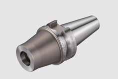
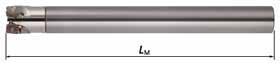
Overhang length for LF is with head mounted. Can also be used with BT30 special machines.


CRKSDCBDMMLF2L4L5LF*
MA15 M08 L120C l M88,5151201018145
15 M08 L160C l M88,5151601018185
MA16 M08 L120C l M88,5161201018145
16 M08 L160C l M88,5161601018185
MA18 M10 L150C l M1010,5181501020180
18 M10 L200C l M1010,5182001020230
MA20 M10 L150C m M1010,5201501020180
20 M10 L200C m M1010,5202001020230
MA23 M12 L200C l M1212,5232001022235
23 M12 L250C l M1212,5232501022285
MA25 M12 L200C l M1212,5252001022235
25 M12 L250C l M1212,5252501022285
MA28 M16 L200C l M1617,0282001024240
28 M16 L300C l M1617,0283001024340
MA32 M16 L200C l M1617,0322001024240
32 M16 L300C l M1617,0323001024340
CRKSDCBDMMLF2L4L5LF*
MA16 M08 L120S l M88,5161201018145
MA20 M10 L150S l M1010,5201501020180
MA25 M12 L200S l M1212,5252001022235
MA32 M16 L200S l M1617,0322001024240
C40, Hub
Vertical Machining Centre BT40
Tool
Grade
Chipbreaker
Cutter Diam. (mm)
Number of Teeth
vc (m/min)
vf (mm/min) fz (mm/t)
ap (mm)
ae (mm)
Coolant Wet
Results
4 corners per side
The high chattering sound typical of thin workpieces is gone and stable machining enables longer tool life.
C50, Mould Parts
Ram type milling machine BT40
Tool
Grade
Chipbreaker
Cutter Diam. (mm)
Number of Teeth
vc (m/min)
vf (mm/min)
fz (mm/t)
ap (mm)
ae (mm)
Coolant
Results
SM490A, Machine Component
Vertical Machining Centre BT50

Tool
Grade
Chipbreaker
Cutter Diam. (mm)
Number of Teeth
vc (m/min)
vf (mm/min)
fz (mm/t)
ap (mm)
ae (mm)
Coolant
Results
SumitomoCompetitor
2 corners per side
Efficiency improved 1,5x, quiet and stable machining.
C50, Machine Component
5-axis Control
Vertical Machining Centre HSK-A100
X2CrNiMo17132, Machine Component
Vertical Machining Centre BT40
Tool
Grade
Chipbreaker
Cutter Diam. (mm)
Number of Teeth
vc (m/min)
vf (mm/min) fz (mm/t)
ap (mm) ae (mm)
Coolant
Results
SumitomoCompetitor
Tool
Grade
Chipbreaker
Cutter Diam. (mm)
Number of Teeth
vc (m/min)
vf (mm/min)
fz (mm/t)
ap (mm)
ae (mm)
Coolant
Results
SCS13, Machine Component
Tool
Vertical Machining Centre BT50
Grade
Chipbreaker
SumitomoCompetitor
2 corners per side
Cermet grades improve surface quality and machining efficiency
SumitomoCompetitor
2 corners per side
Stability without chatter even in groove milling with overhang of 120 mm (L/D=6)
SumitomoCompetitor
4 corners per side
Excellent surface accuracy, applicable to finishing operations (ae = 0,1 mm).
Cutter Diam. (mm)
Number of Teeth
vc (m/min)
vf (mm/min) fz (mm/t) ap (mm) ae (mm)
Coolant
Results
Longer tool life without chipping even when machining the black scale layer.
X5CrNiS18 10, Semiconductor Device
Horizontal Machining Centre BT50
Tool
Diam. (mm) Number of Teeth
SumitomoCompetitor
Stainless Steel Duplex SUS Machine Component
Multi-tasking Machine
Tool
SumitomoCompetitor
(mm/min)
(mm/t)
Results
Improved surface finish quality and reduced burrs, cutting post-processing time by 50%

(mm/t)
ap (mm)
ae (mm)
Coolant
Results
GG-30, Machine Component
Vertical Machining Centre BT50 SumitomoCompetitor
Tool
Grade
Chipbreaker
Cutter Diam. (mm)
Number of Teeth
vc (m/min)

vf (mm/min)
fz (mm/t)
ap (mm)
ae (mm)
Coolant
Results

Tool
Grade
Chipbreaker
Cutter Diam. (mm)
Number of Teeth
vc (m/min)
vf (mm/min)
fz (mm/t) ap (mm)
ae (mm)
Coolant
Results
Helical machining with 1,5 times higher efficiency and two times longer tool life
GG-25, Machine Component
Horizontal Machining Centre BT50
Tool
Grade
Chipbreaker
Cutter Diam. (mm)
Number of Teeth
vc (m/min)
vf (mm/min)
fz (mm/t)
ap (mm)
ae (mm)
Coolant
Results
GG-25, Railway Component
Tool
Grade
Chipbreaker
Cutter Diam. (mm)
Number of Teeth
vc (m/min)

vf (mm/min)
fz (mm/t)
ap (mm)
ae (mm)
Coolant
Results
Suppresses burrs and extends tool life by 1,6x.
SumitomoCompetitor
Quiet machining noise and improved machining efficiency Excellent flatness and surface finish with 3 µm parallelism and 4 µm flatness.
Increased cutting edge sharpness enables stable machining with efficiency improved 4,5x. Vertical Machining Centre GG-25, Crank Shaft
SumitomoCompetitor
Plastics Electronics
Vertical Machining Centre BT40
Tool
Grade
Chipbreaker
Cutter Diam. (mm)
Number of Teeth

vc (m/min)
vf (mm/min)
fz (mm/t)
ap (mm)
ae (mm)
Coolant
Results
FRPP Resin Industrial Machine Component
Horizontal Machining Centre BT50
Tool Grade
Chipbreaker
Cutter Diam. (mm)
Number of Teeth
vc (m/min)
vf (mm/min)
fz (mm/t)
ap (mm)
ae (mm)
Coolant
Results
Titanium Alloys, Aircraft Component
Tool
Grade
Chipbreaker
Cutter Diam. (mm)
Number of Teeth
vc (m/min)
vf (mm/min)

fz (mm/t)
ap (mm)
ae (mm)
Coolant
Results
Lower noise level due to improved cutting performance.
Al-Alloy A2025, Machine Component
Ram type milling machine BT40

Tool
Grade
Chipbreaker
Cutter Diam. (mm)
Number of Teeth
vc (m/min)
vf (mm/min)
fz (mm/t)
ap (mm)
ae (mm)
Coolant
Results
Very little dimensional fluctuation and machining precision is stable.
Al-Alloy A5052 Machine Component
5-axis Control Vertical Machining Centre HSK-A100
Vertical Machining Centre BT50 Minimized wall surface step, increasing machining efficiency.

Tool
Grade
Chipbreaker
Cutter Diam. (mm)
Number of Teeth
vc (m/min)
vf (mm/min)
fz (mm/t)
ap (mm)
ae (mm)
Coolant
Results
Stable machining without chatter even at overhang of 100 mm (L/D=4)
Tool
Grade
Chipbreaker
Cutter Diam. (mm)
Number of Teeth
vc (m/min)
vf (mm/min)
fz (mm/t)
ap (mm)
ae (mm)
Coolant
Results
No chipping, longer tool life with reduced burrs.
Tool
Grade
Chipbreaker
Cutter Diam. (mm)
Number of Teeth
vc (m/min)

vf (mm/min)
fz (mm/t)
ap (mm)
ae (mm)
Results
2 corners per side
Coolant Wet Wet No chatter, Efficiency increased 12x or more.

Tool Grade
Chipbreaker
Cutter Diam. (mm)
Number of Teeth
vc (m/min)
vf (mm/min) fz (mm/t) ap (mm) ae (mm)
2 corners per side
Coolant Dry Dry
Results
Capable of low-chatter machining even at a tool overhang amount of 200 mm.

Cutter Diam. (mm)
Number of Teeth vc (m/min)
vf (mm/min)
Coolant
Results
of

Cutter Diam. (mm)
Number of Teeth vc (m/min)
vf (mm/min) fz (mm/t) ap (mm) ae (mm)
Coolant Wet Wet
Results
increased 5x or more, for reduced tool costs.
(Germany)
SUMITOMO ELECTRIC Hartmetall GmbH Konrad-Zuse-Straße 9, 47877 Willich
Tel. +49 2154 4992-0, Fax +49 2154 4992-161 Info@SumitomoTool.com www.SumitomoTool.com
Distributed by:
(UK and Ireland)
SUMITOMO ELECTRIC Hardmetal Ltd. 3 Paper Mill Drive Redditch, B98 8QJ, UK
Tel. +44 1844 342081, Fax: +44 1844 342415 InfoUK@SumitomoTool.com www.SumitomoTool.com

E-172-08/23-SE