Education — Architectural Design I (2025)
Location • New Haven, CT, USA
Critic • Nicholas McDermott
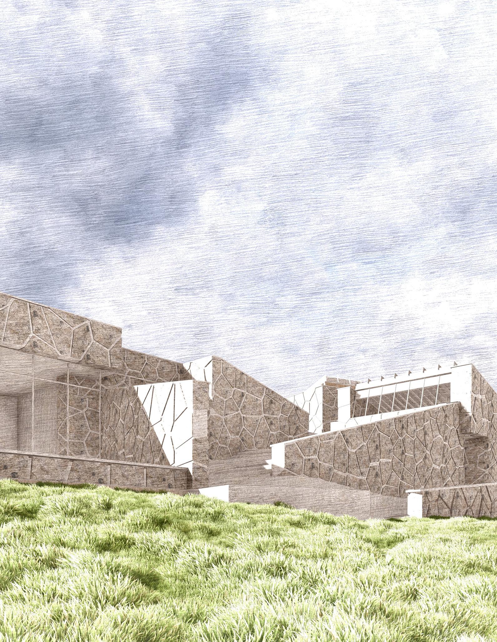
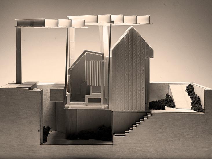
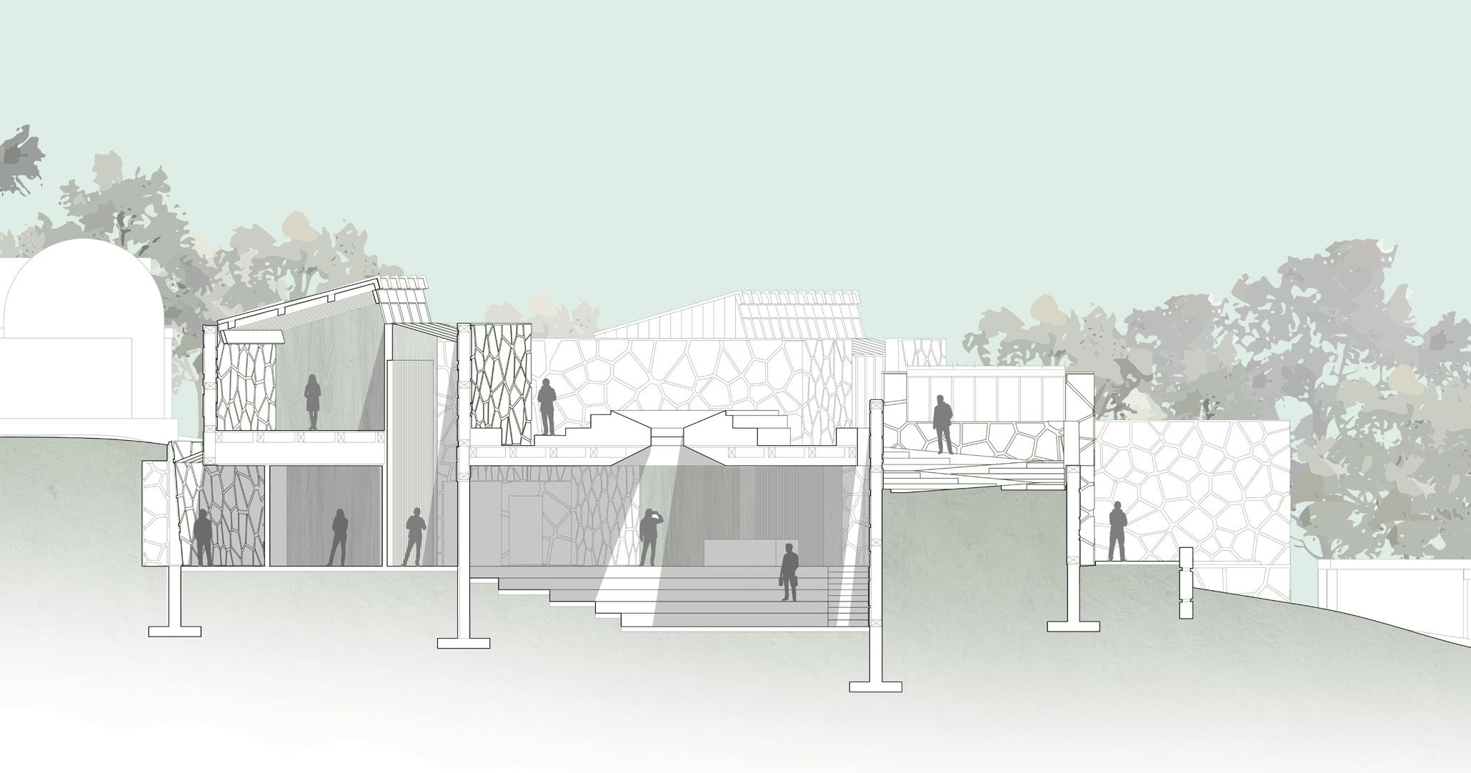
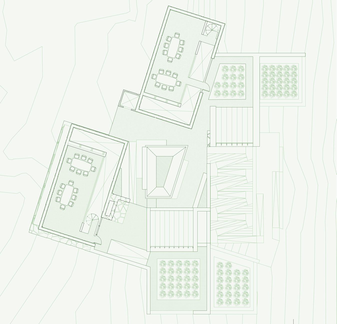
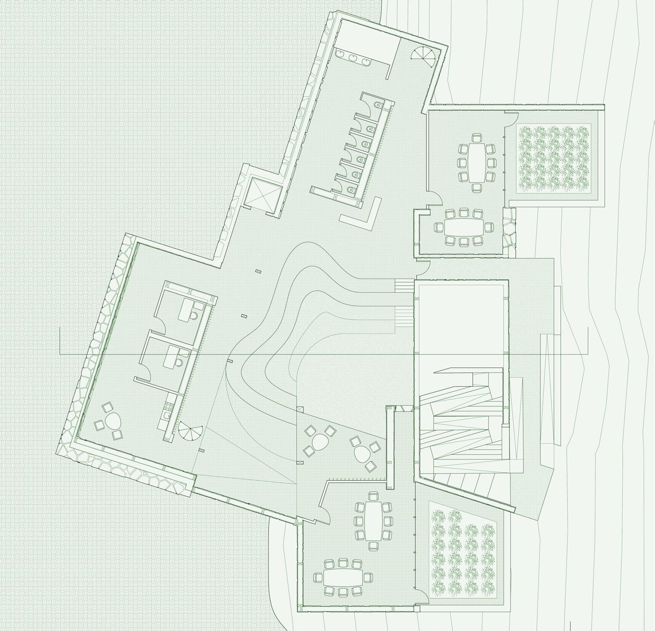
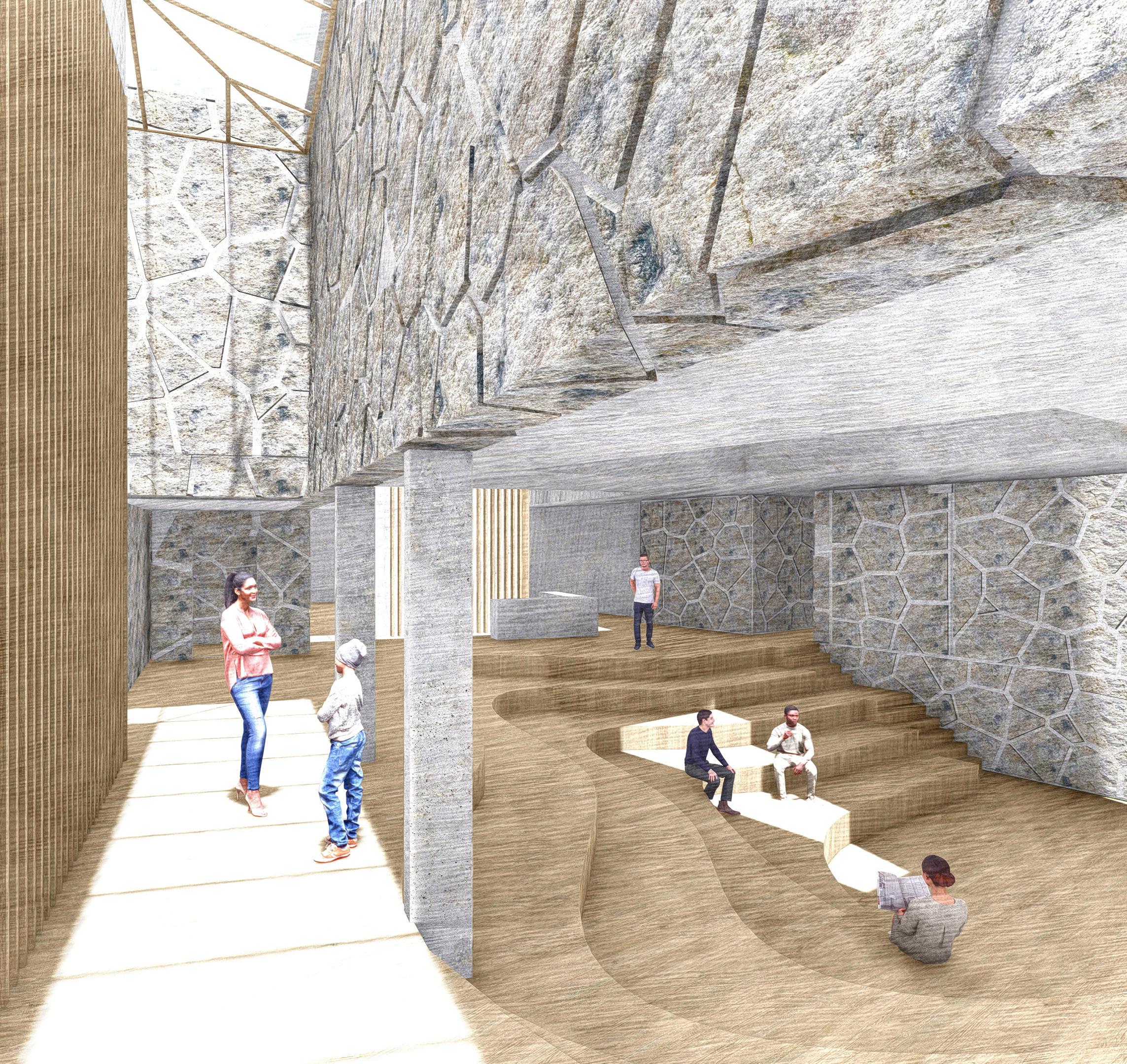
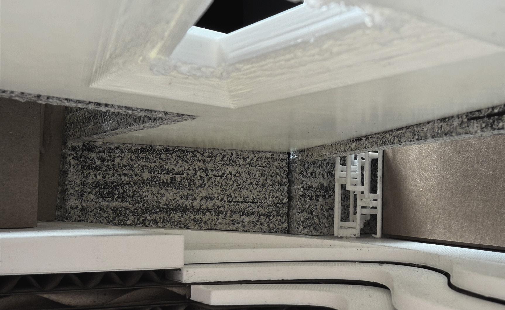
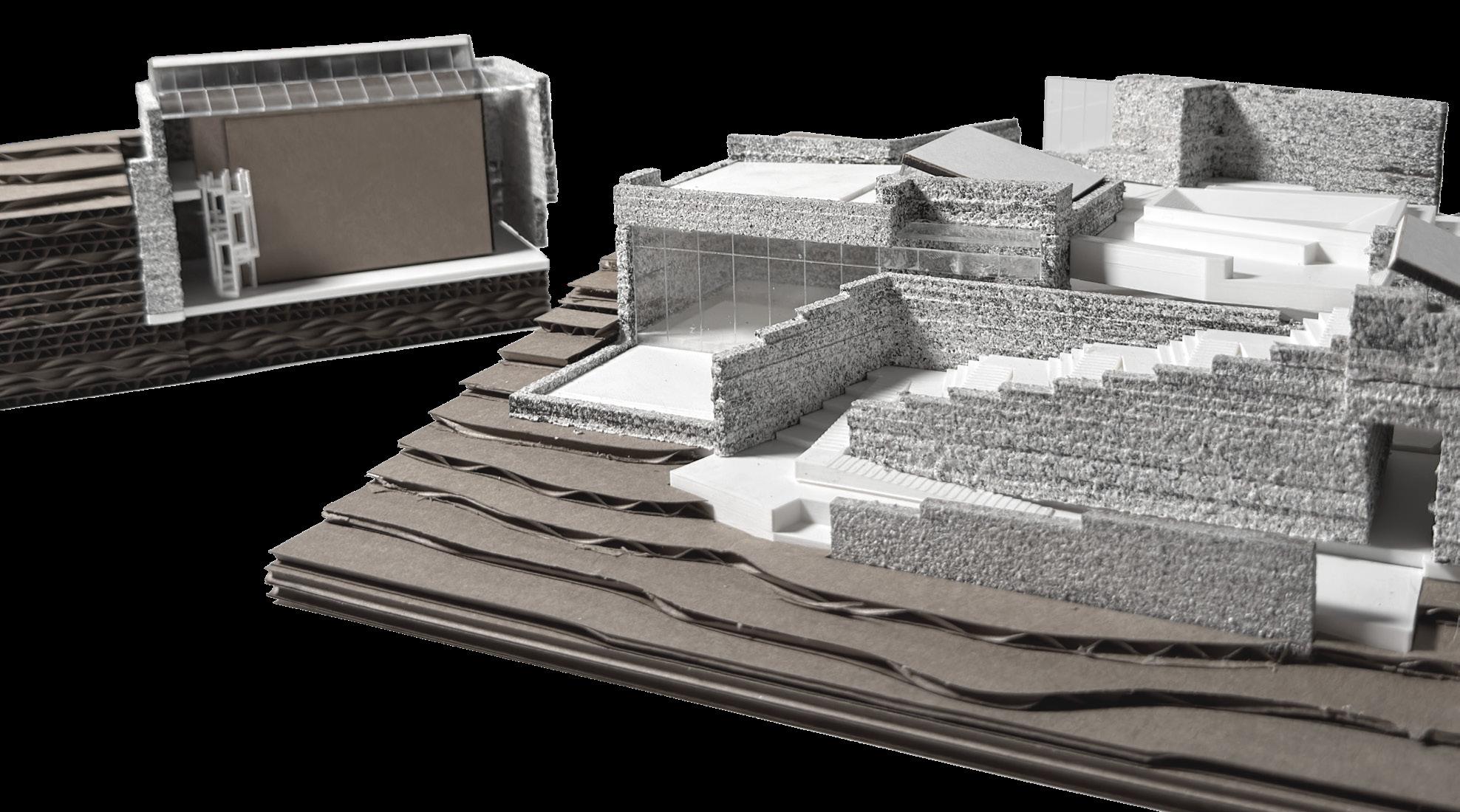
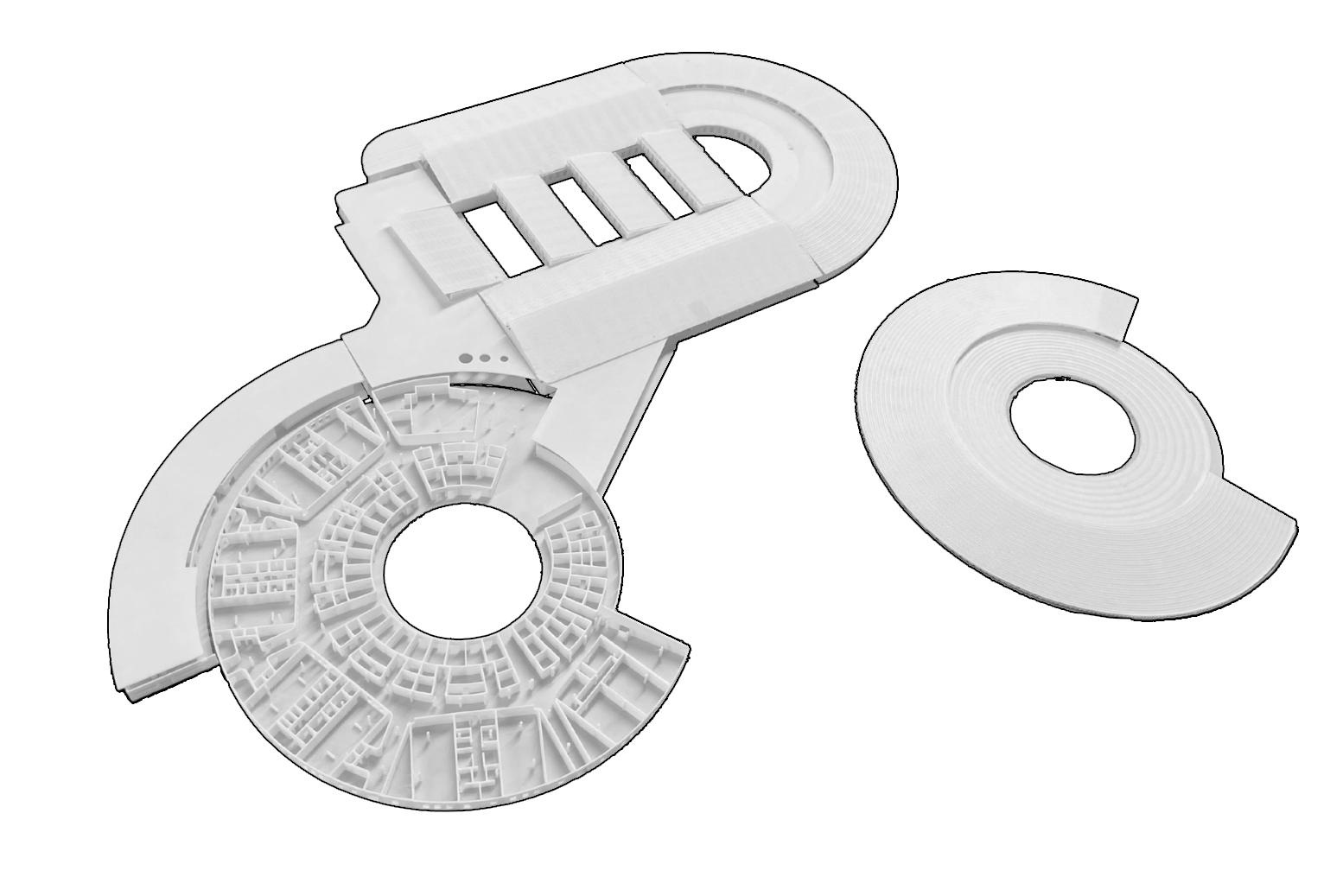
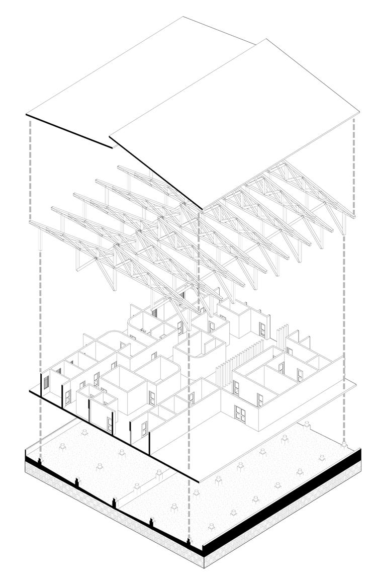
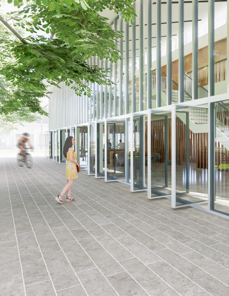
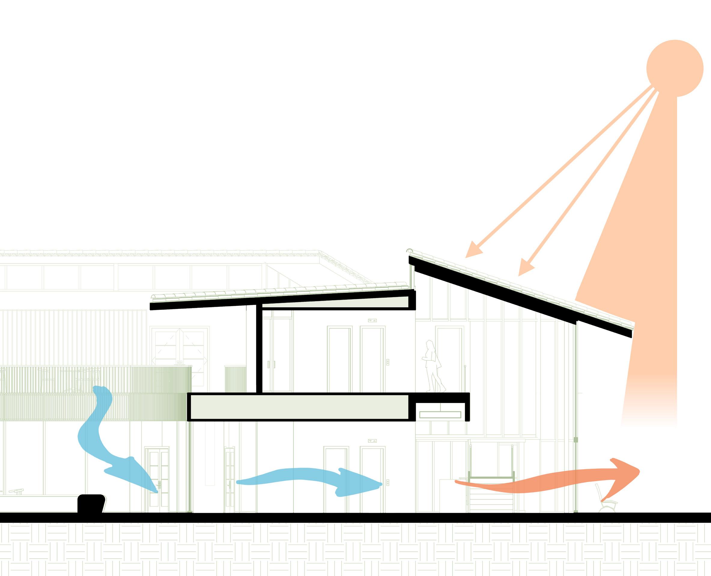
Yale Farm Commons strives to provide academic programming space while minimizing disruption to its site. To evoke its natural New England setting, the building takes the local New England rock wall and weaves it up the sloped site. Between enclosed spaces, an accessible path is created to preserve and enhance the experience of exploration the site currently offers. Additionally, the project culminates a study of the movement of light to illuminate a variety of below-grade spaces, creating exciting moments of interaction which offer diverse uses for students and visitors alike.
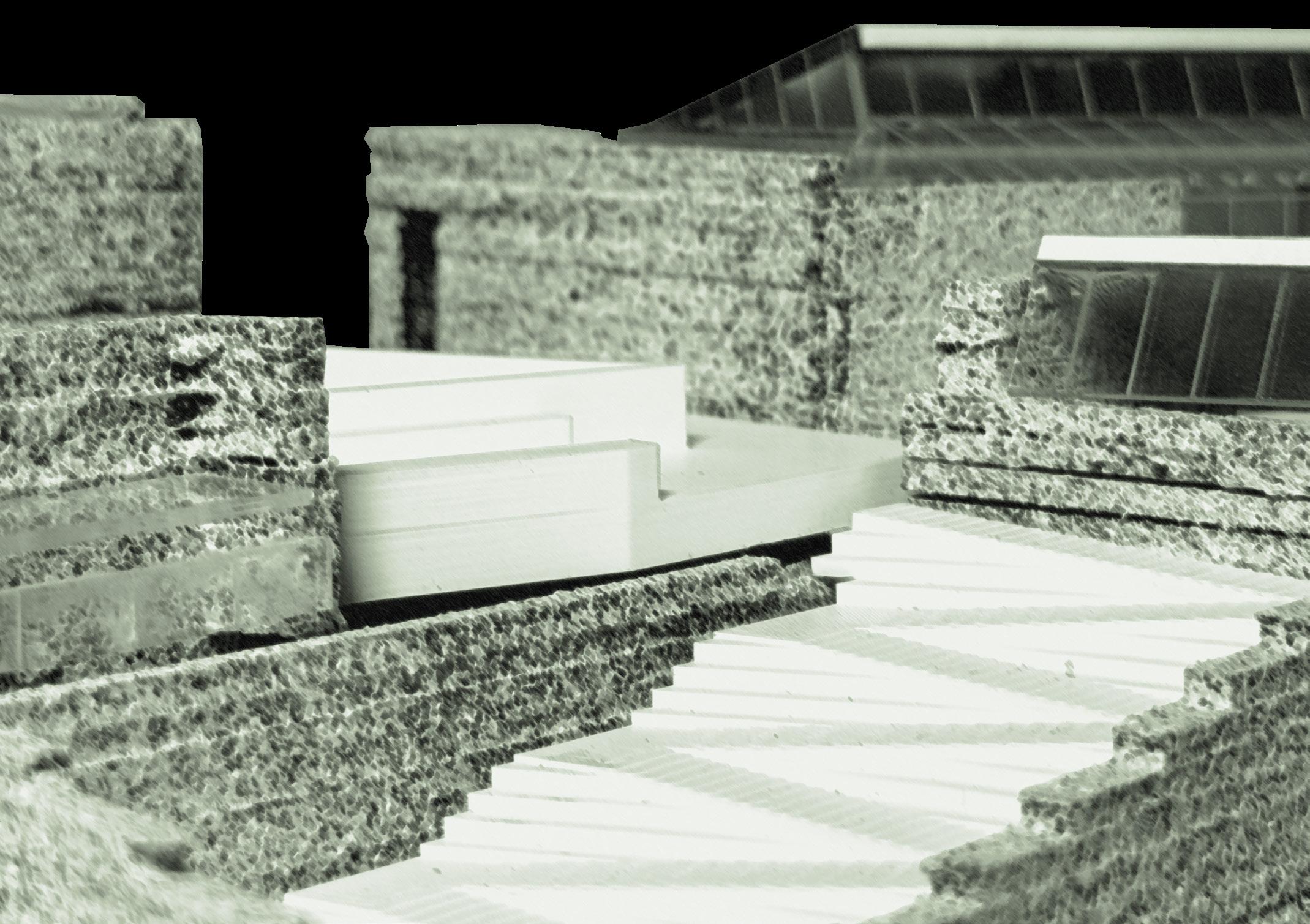
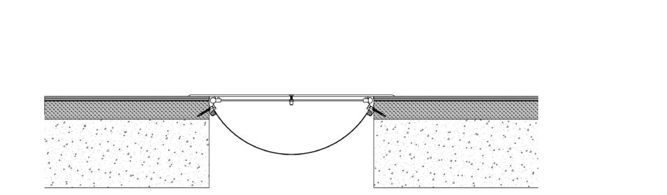
Section oblique, conceptual 1” = 16’-0” scale
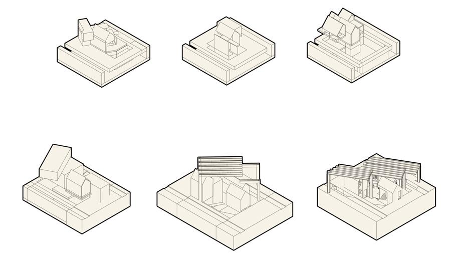
massing
Design studies at the start of the process began an exploration of light and how it travels from seen to unseen spaces. Studies began with diagramming tension and how light can accentuate it in model form, and concluded with creating light and space in hostile, industrial environments.
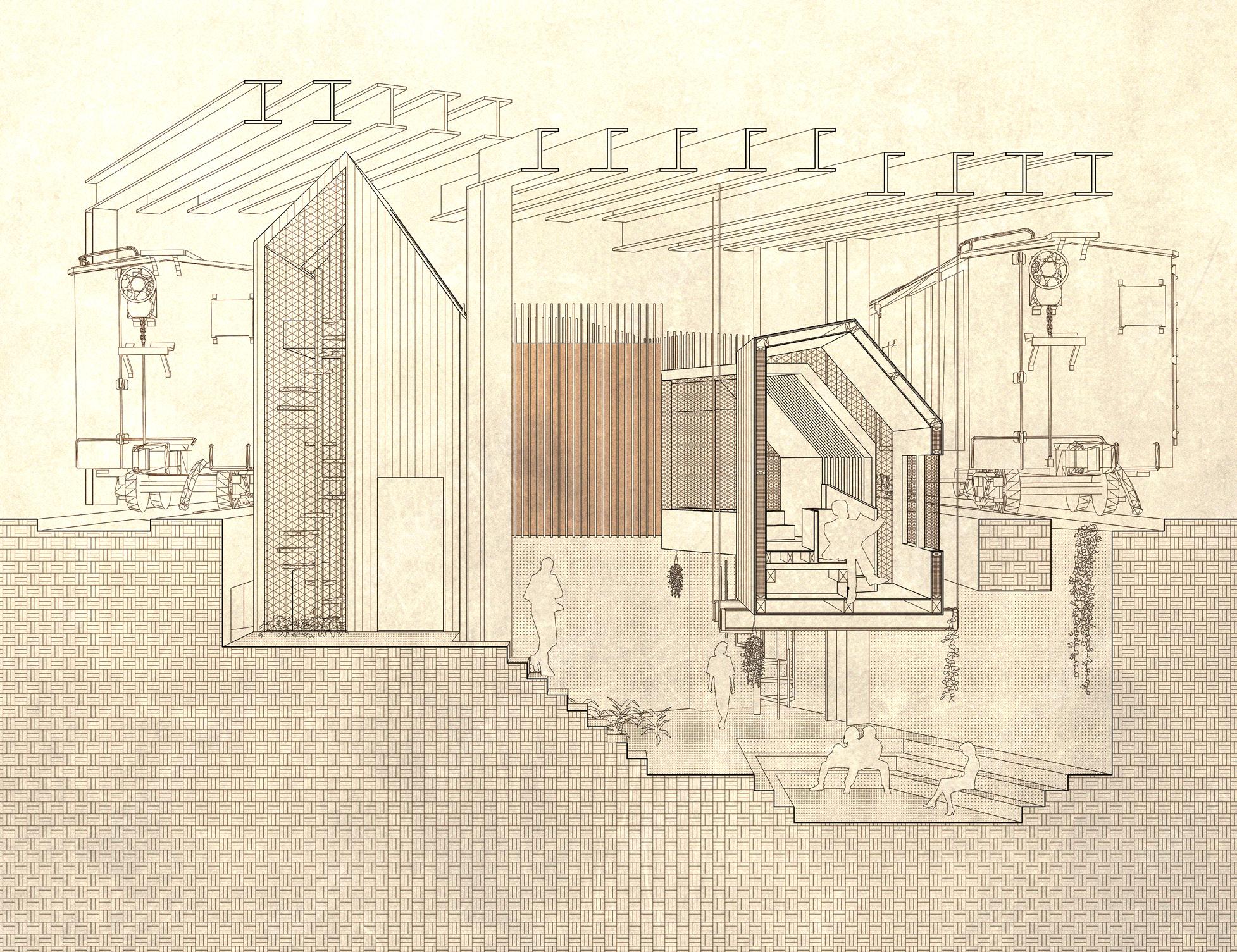
Section perspective, conceptual 1” = 16’-0” scale
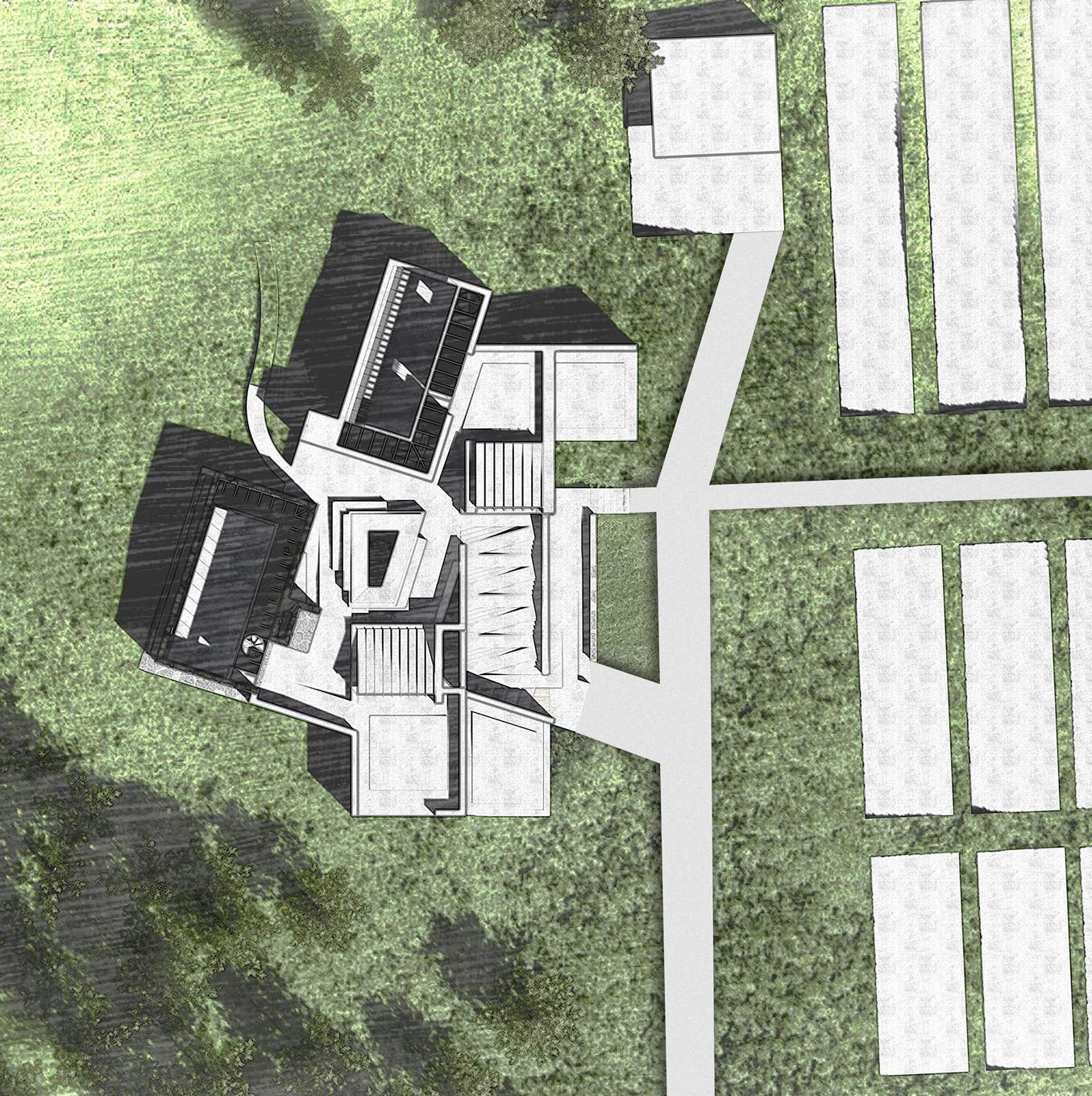
Site plan
1” = 60’-0” scale

Inspired by the natural quality of New England’s stone walls, the building’s form meanders as it slopes up its site, with walls splitting off to form enclosed spaces. These coves are sunken down to ground level, and circulation between them moves underneath the hill, preserving public access through the site.

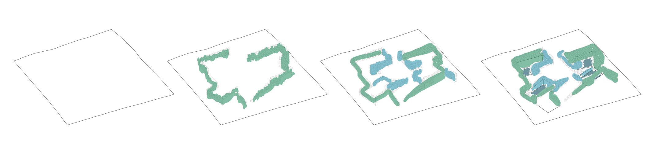
Light and site studies come together to form the interior spaces. Heavy stone walls pull back to allow for circulation space, and rigid perimeters give way to a nexus at its center. This flowing sunken gathering area doubles as a lecture and social space, acting as a heart where pockets of light and material converge.
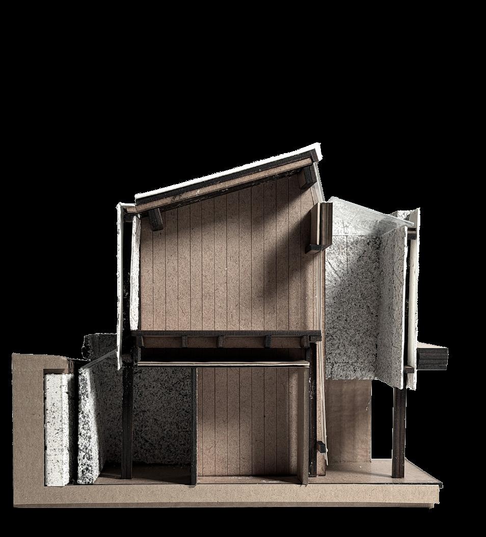
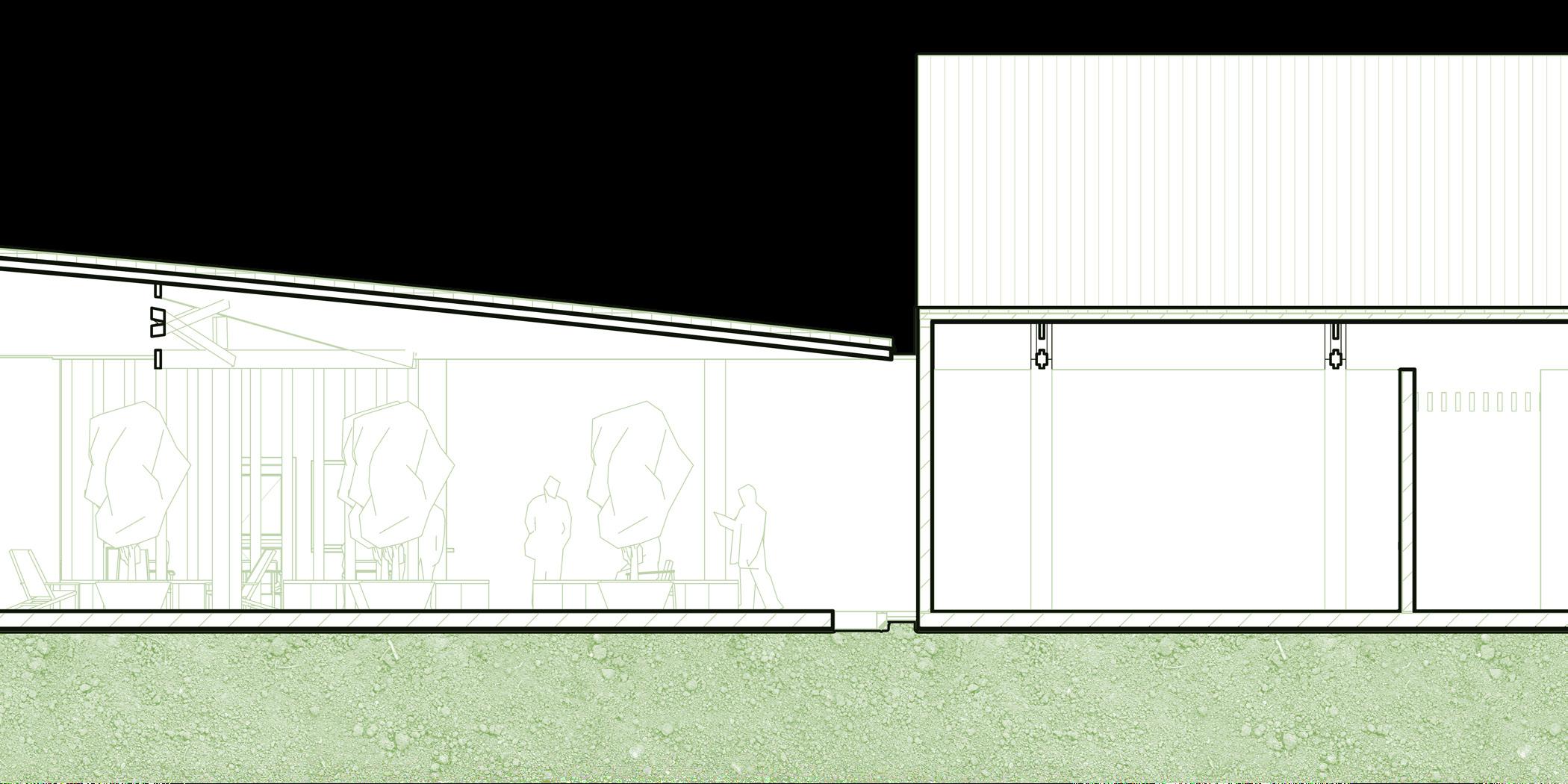
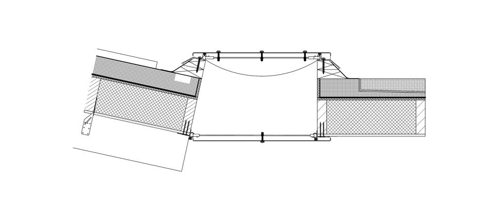
Section cut
1” = 24’-0” scale
Healthcare — Major Qualifying Project (2025)
Location • Les Cayes, Haiti
Critics • Soroush Farzin | Leonard Albano, PE | Nancy Ma
Team* • Benjamin Coe | Marco Legros | Pratham Patel | Spencer Romain
Roles • Master Planning | Program Development | Project Management | Digital Modeling and Drafting
Awards • WPI Provost Award for Outstanding MQPs
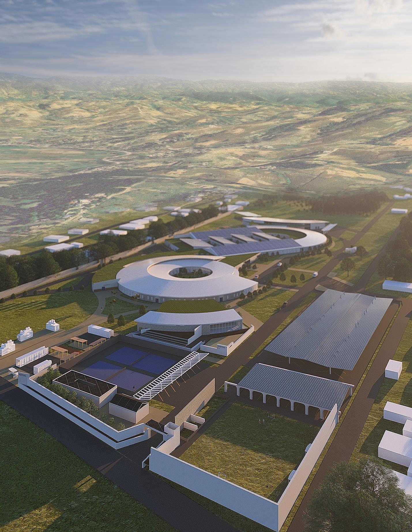
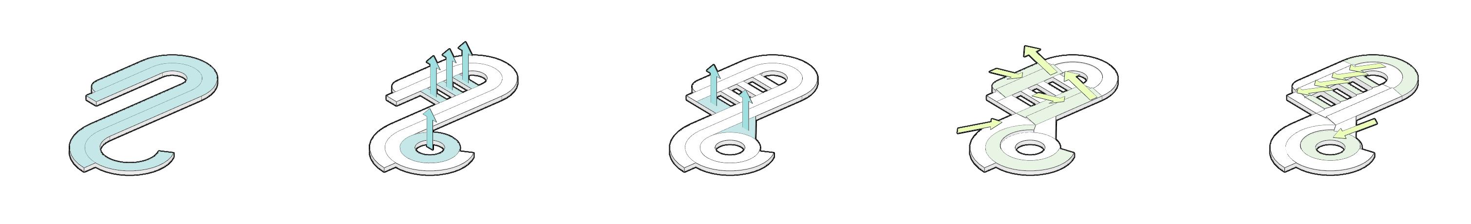
In Haiti, healthcare facilities are plagued with overcrowding, underinvestment, and intense weather and seismic events. These challenges overwhelm existing healthcare facilities, highlighting a need for change. Translated as “Source of Life,” Hôpital Source de Vie offers world-class facilities for patients. In the event of a natural disaster, the building is protected by a seismic-resistant structure, and the site features flexible space for capacity to be added quickly. For its region of Les Cayes and beyond, the hospital is intended to serve as a beacon, offering a view of how healthcare across the country can be transformed.
*All works presented are of my own creation unless otherwise noted.
Upon consulting hospital design professionals from Build Health International and Haitian healthcare experts, we devised a program encompassing the core facilities of a general hospital.
We let the form take on a flow that smoothly united these facilities with a focus on creating outdoor space and enabling natural ventilation.
Outpatient Clinic
Inpatient Wards
Surgical Department
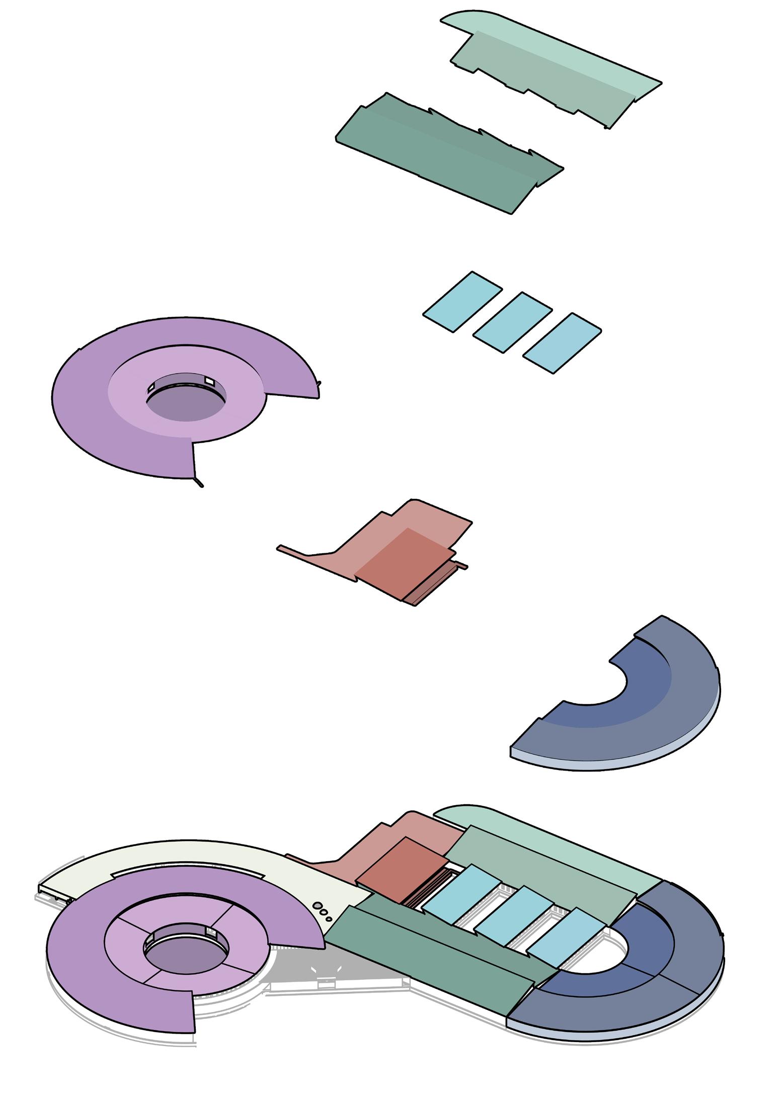
Maternity Clinic
Emergency Department
Axonometric program diagram
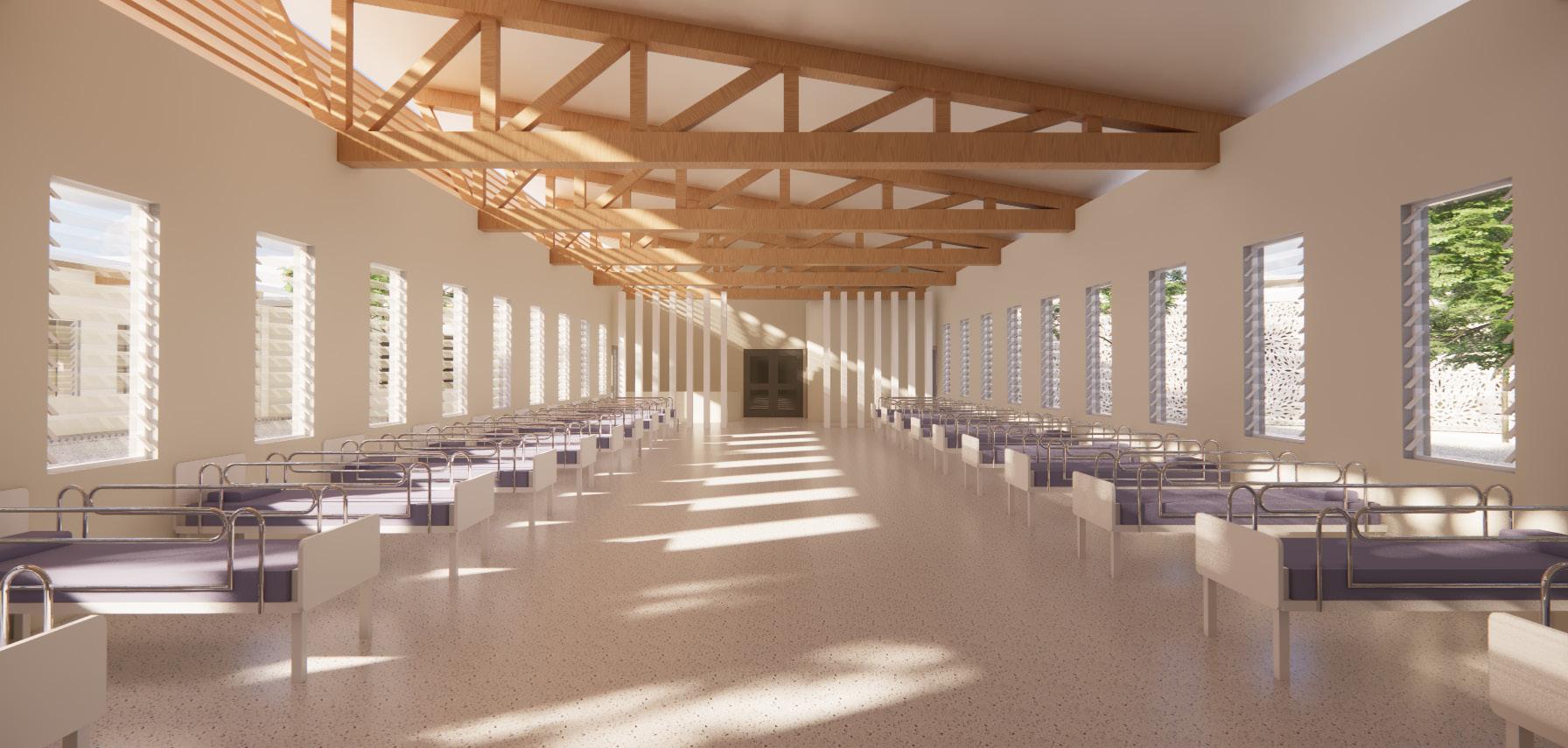
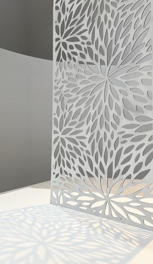
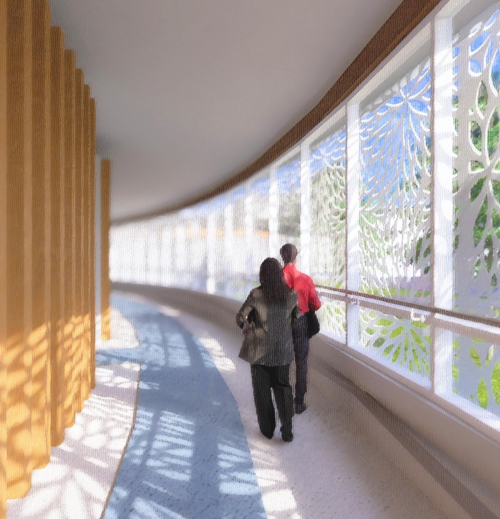
The hospital spaces are designed to inspire and perform. Operable jalousie windows move natural air into patient wards, while wrought iron perforated panels offer protection from solar heat gain with a local flair.
display model 1” = 20’-0” scale
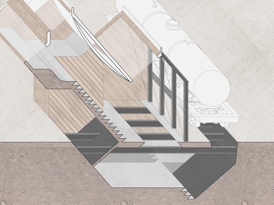
A mass-timber structural frame keeps the hospital standing during violent earthquakes, while consistent columns spans enable flexible floor configurations. Bridging the different wings of the hospital, I designed expansion joints in accordance with ASCE standards which allow each structurally isolated area to safely sway against its neighbors during a seismic event.
Within the base-isolated foundation, cavities guide waste and flood water to collection tanks, where they are pumped to an on-site treatment plant for reuse as potable water.
Exploded axonometric view
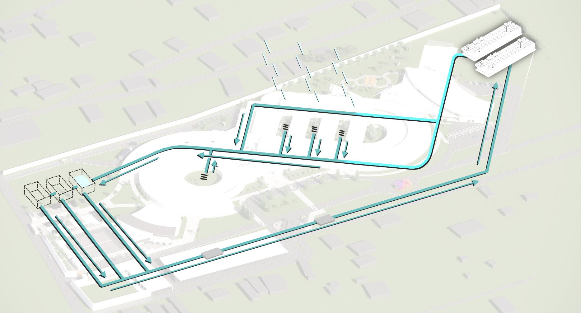
Water management diagram
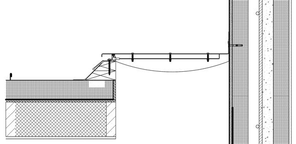
Detail drawings and section cut
1” = 2’-0” scale (details)
3” = 32’-0” scale (section)
Transportation — Personal Design Project (2024)
Location • Newark, NJ, USA
Floor Area • 3,700,000 sq ft
Aircraft Capacity • 37 Multiple Aircraft Ramp System gates
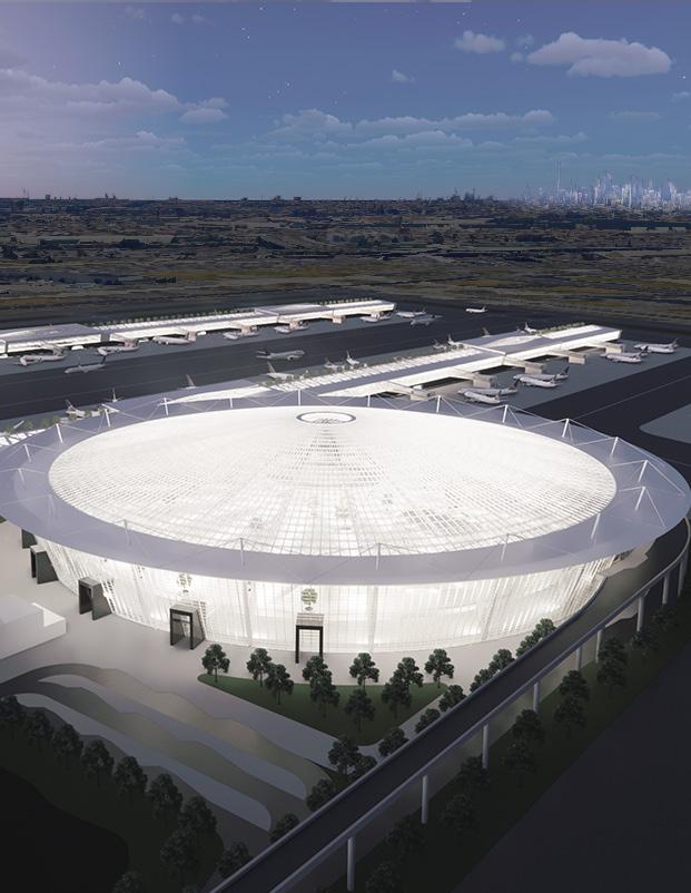
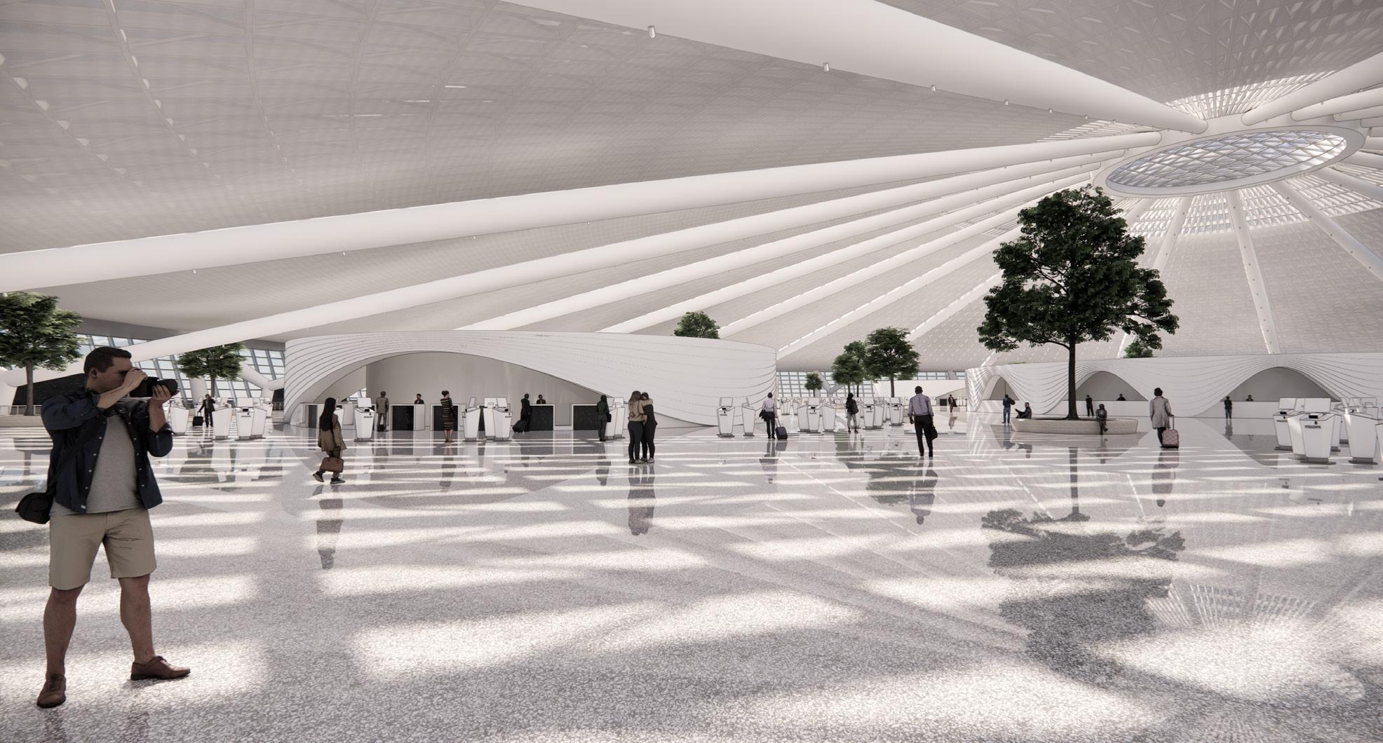
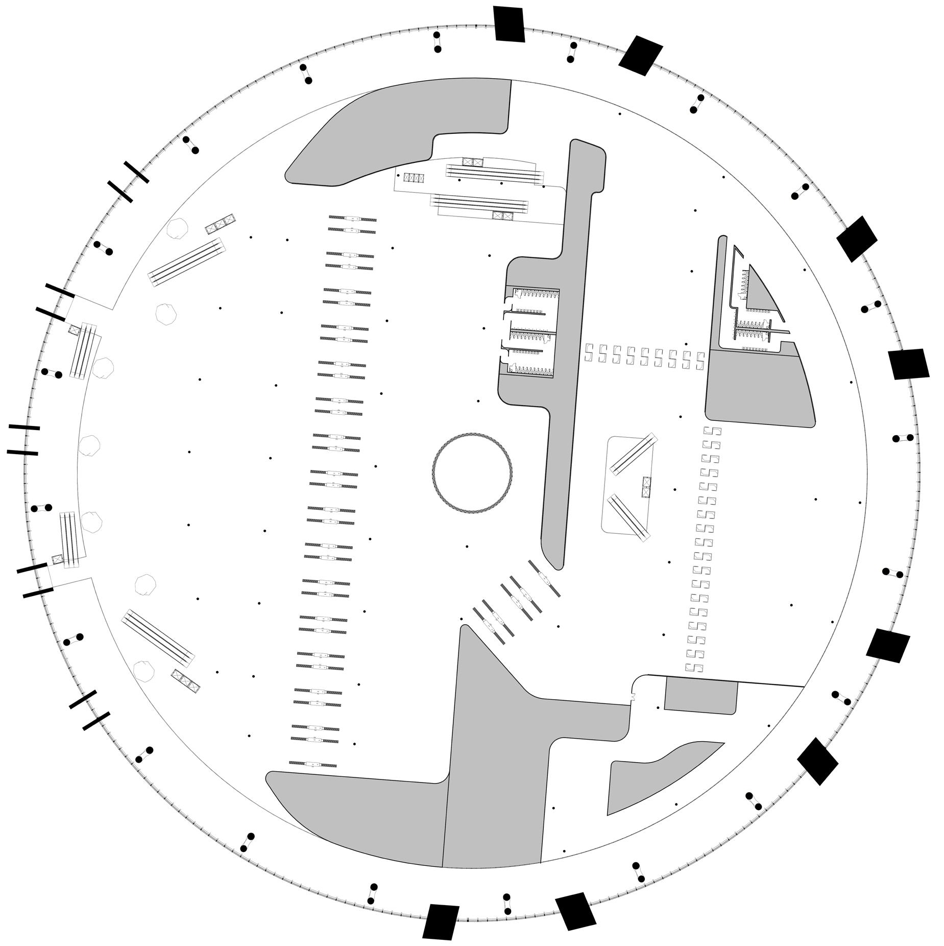
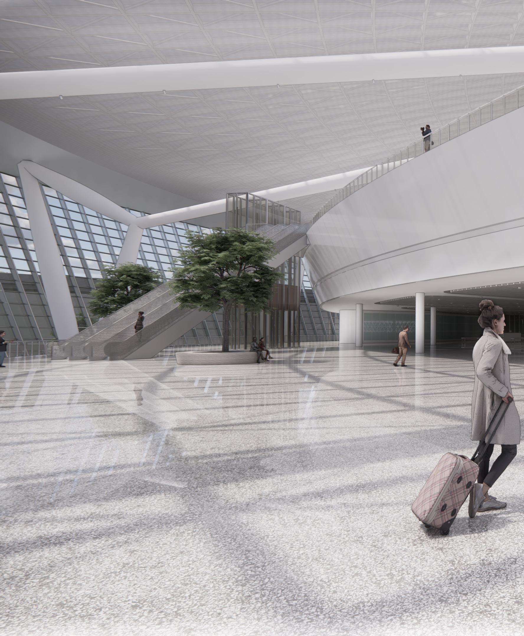
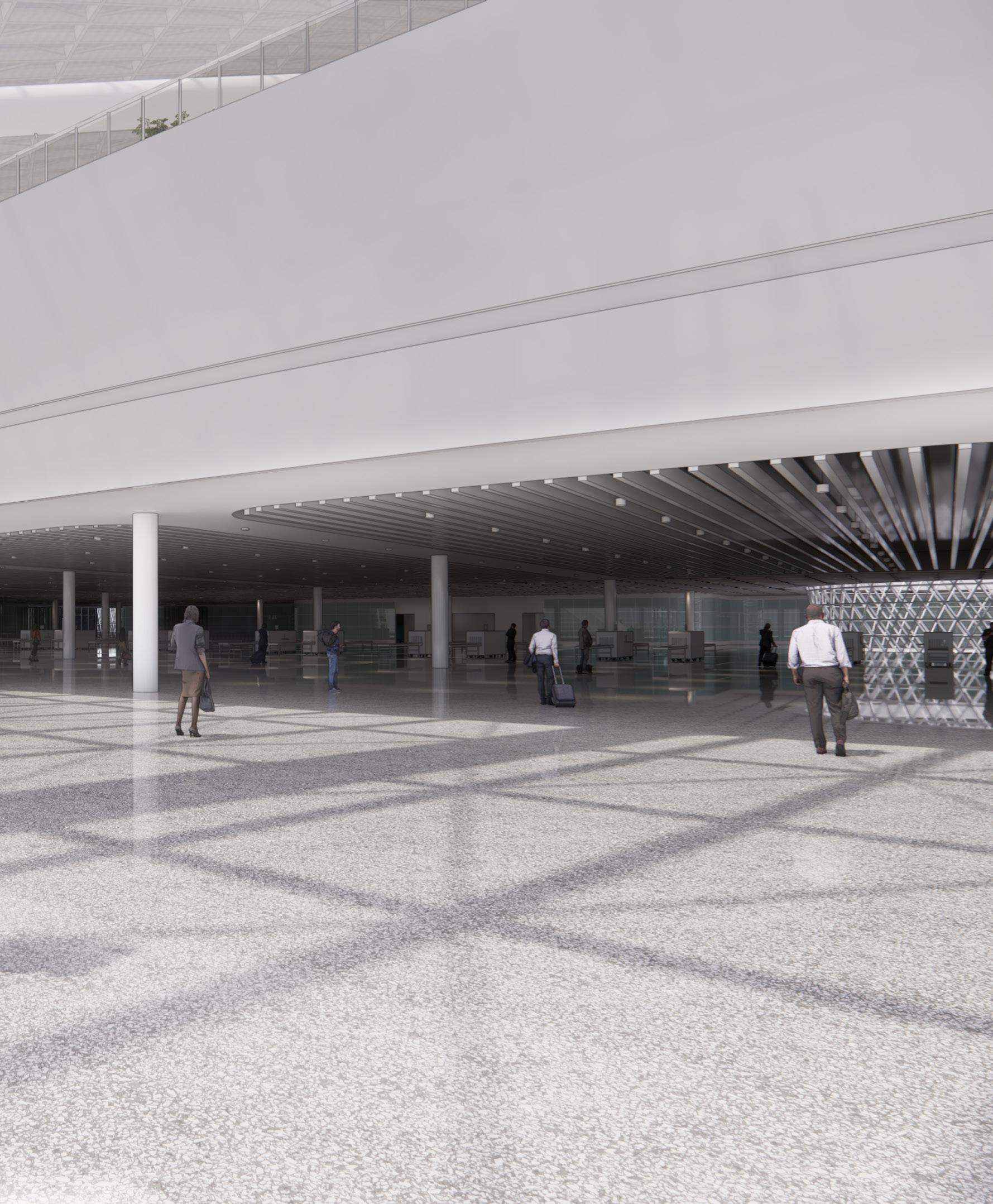
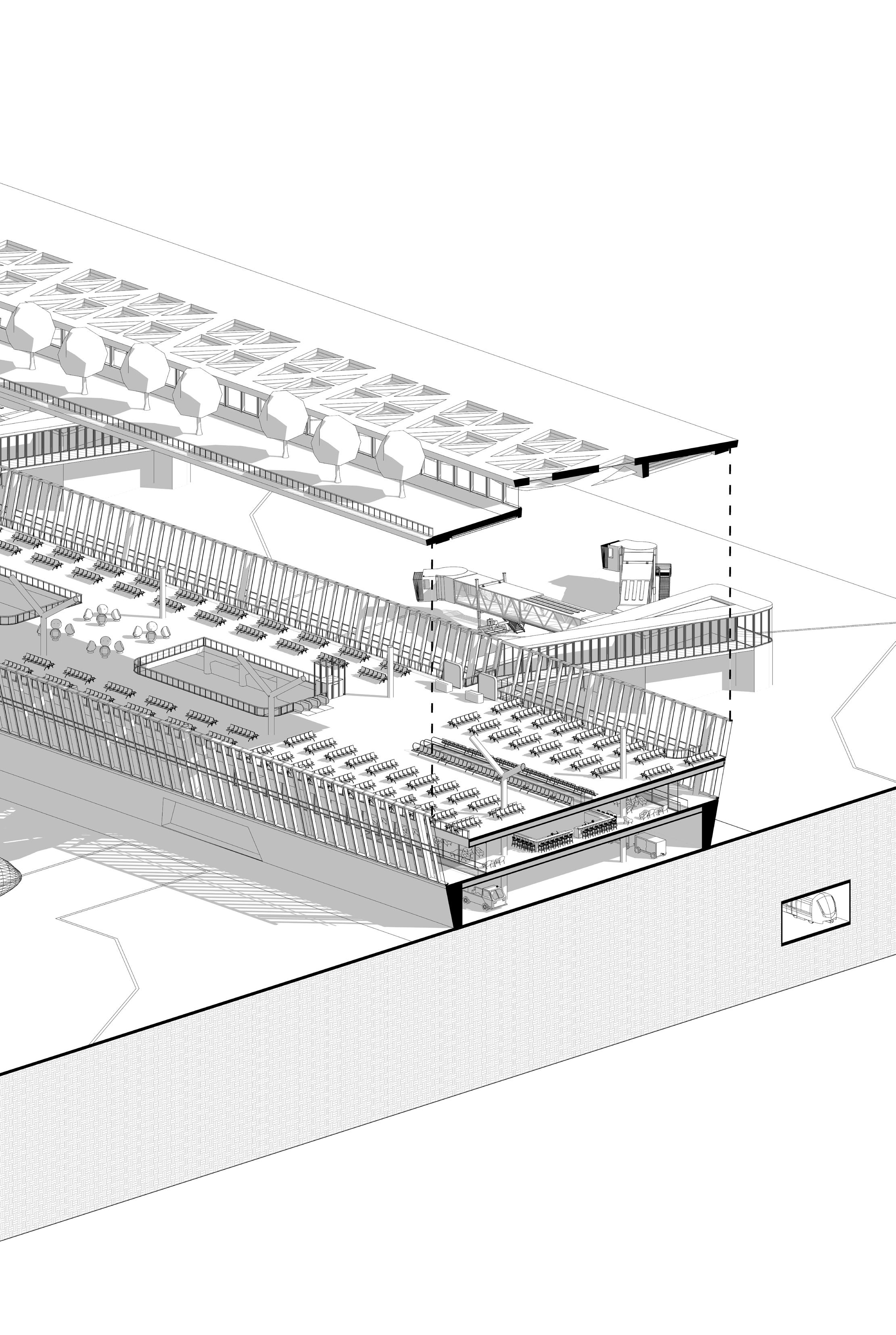
Designed as the capstone for the ongoing redevelopment of Newark Liberty International Airport, Terminal C will take its predecessor’s place as the busiest single terminal of all three major New York City area airports. Its operator, United Airlines, needs a facility that can handle the throughput demanded from an integrated hub for domestic and international air traffic. At the same time, its passengers expect a gateway worthy of New York: an extension of the vision set forth at the LaGuardia and John F. Kennedy Airports. Constructed within the boundaries of the existing facility, the new Terminal C offers a solution to a complicated site while delivering an exemplary airport experience.
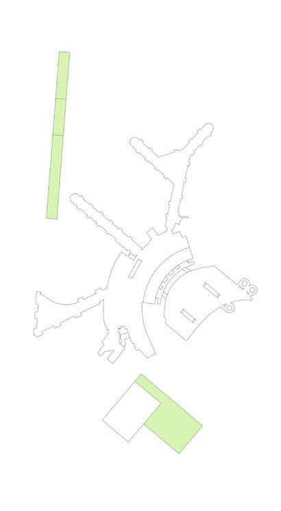

The first challenge when planning Terminal C was to ensure it could be constructed while the existing terminal remained operational. The construction of the parking garage opens a large footprint for the headhouse building to be constructed, while the boarding concourses are designed to be constructed in segments to allow old gates to close as new ones come online.
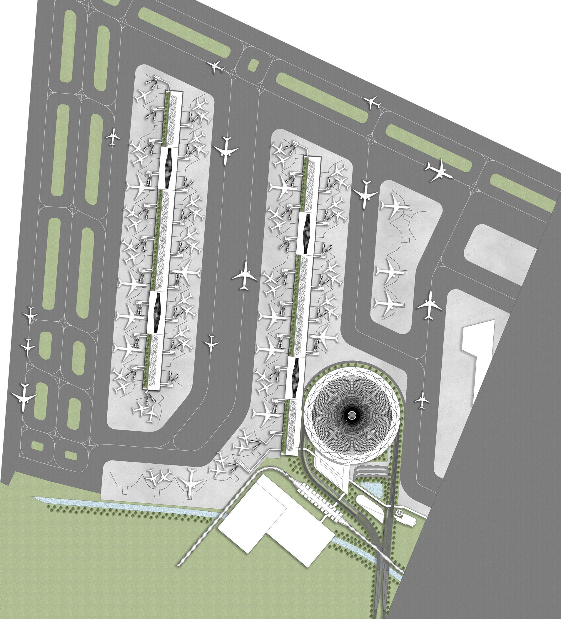
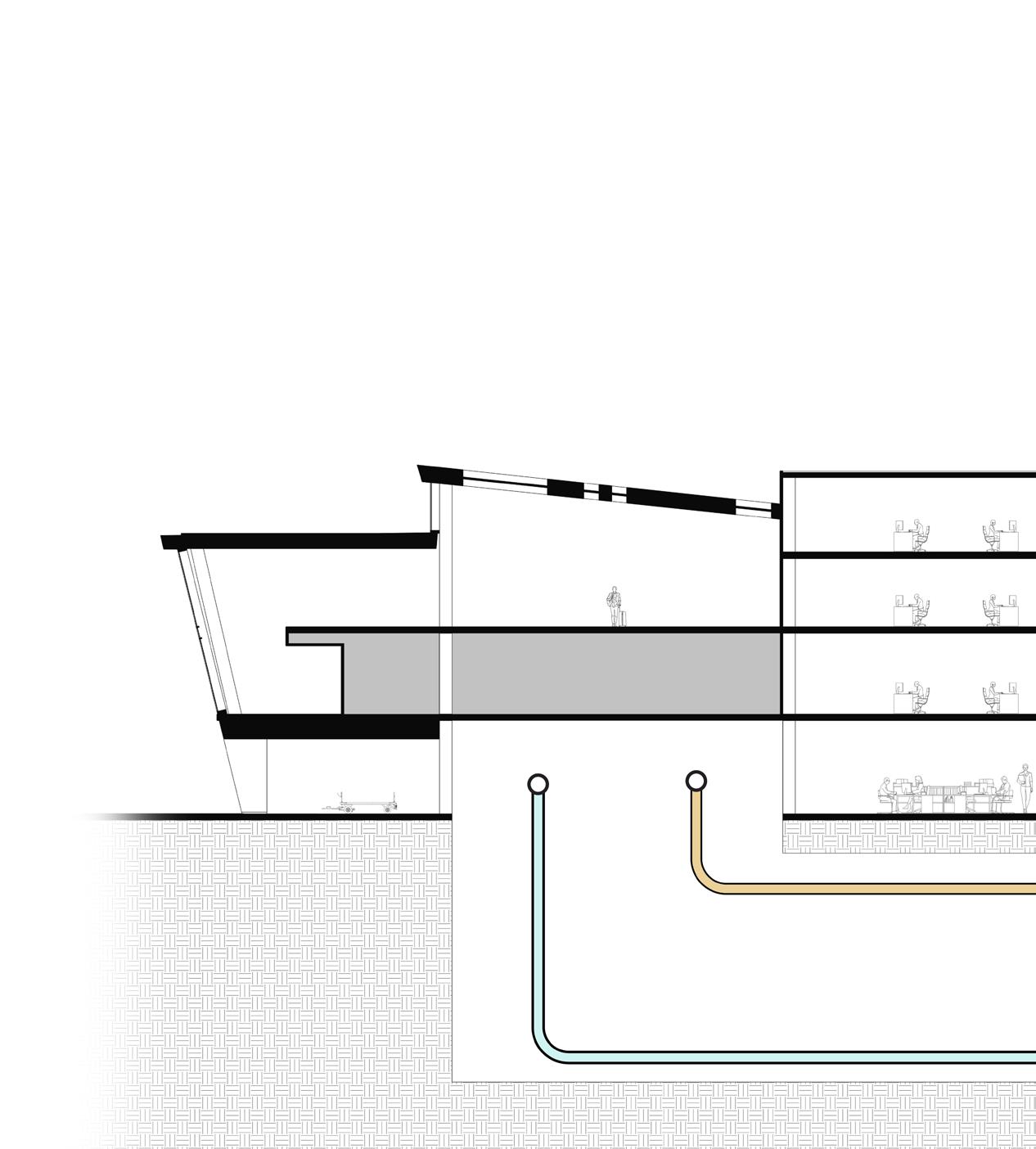
The headhouse marks the start and the end of the journey. Check-in, security, and baggage halls are all placed on different levels, reducing the building’s footprint. This move allows the headhouse to be built in one stage, reducing construction phasing complexity.
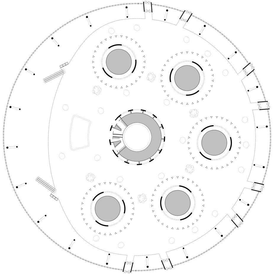
Headhouse, check-in and retail level Plan: 1” = 64’-0” scale
Headhouse, security and customs level
1” = 32’-0” scale
Headhouse, security checkpoint rendering
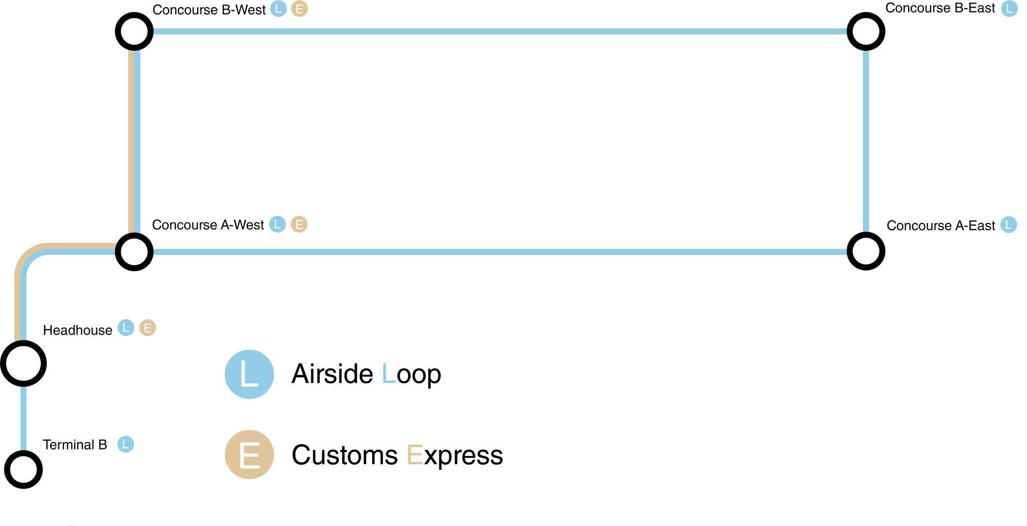
The automated people mover (APM), which connects the concourses to the headhouse, runs in a loop that minimizes walking times. This configuration allows the concourses such lengths as to accommodate up to 72 aircraft.
The APM interchange in the headhouse, in addition to guiding the movement of passengers to the APM system, provides vertical circulation for checked luggage to move to the concourses.

Headhouse APM interchange rendering
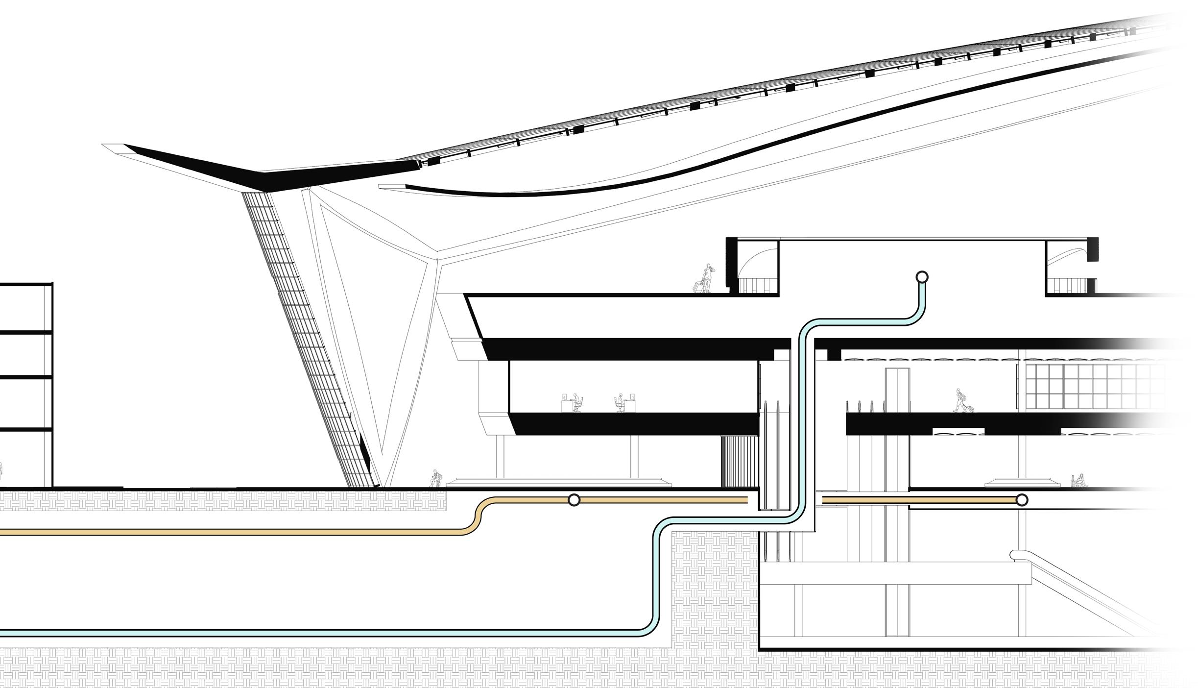
Baggage movement diagram 1” = 16’-0” scale
Concourse, isometric projection 1” = 16’-0” scale
Concourse APM interchange rendering 1/8” = 1’-0” scale
The boarding concourses, designed around a modular construction plan that reduces interference with airport operations, are designed around simplicity and clarity. Below the departures level, the sterile arrivals corridors are placed along the windows, opening flexible space in between for lounges, restaurants, and other amenities.
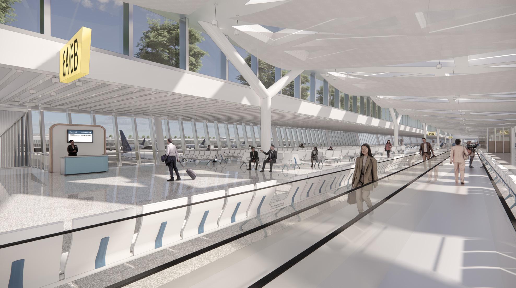
Concourse rendering
Civic and Community — Architectural Design IV (2023)
Location • Miami, Florida, USA
Critics • Shichao Liu | Navneet Anand
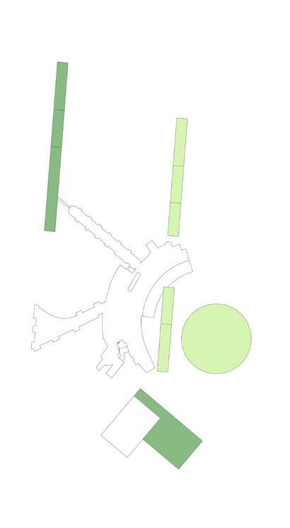
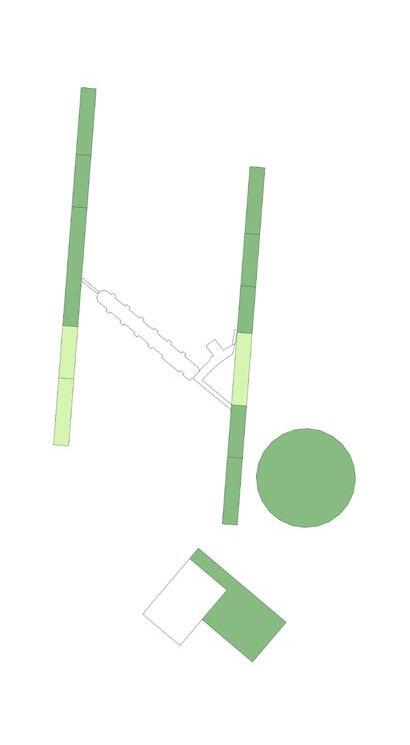
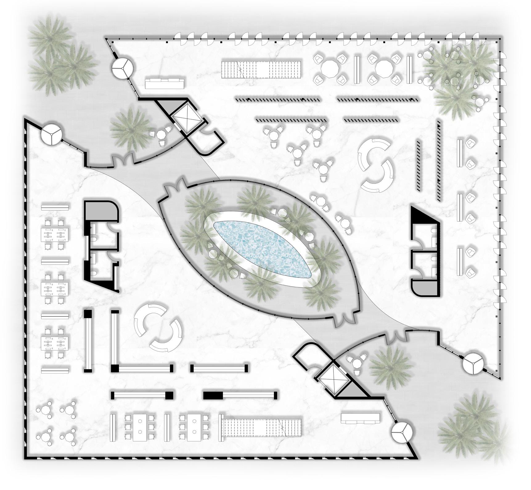
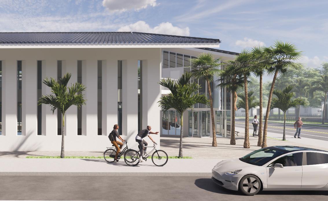
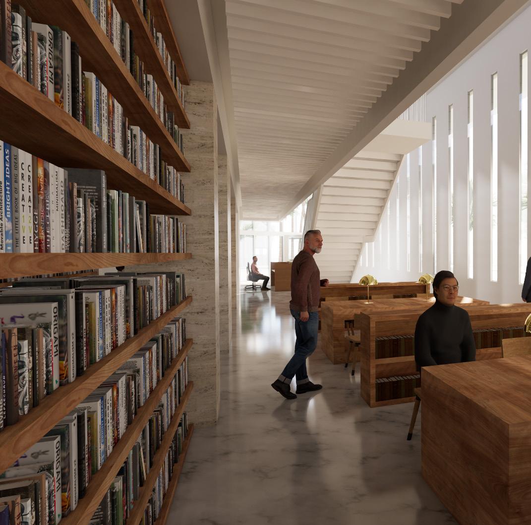
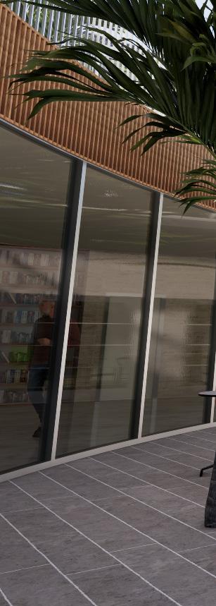
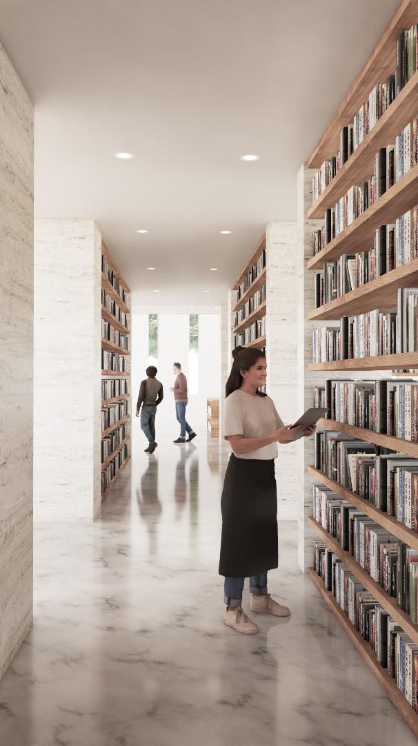
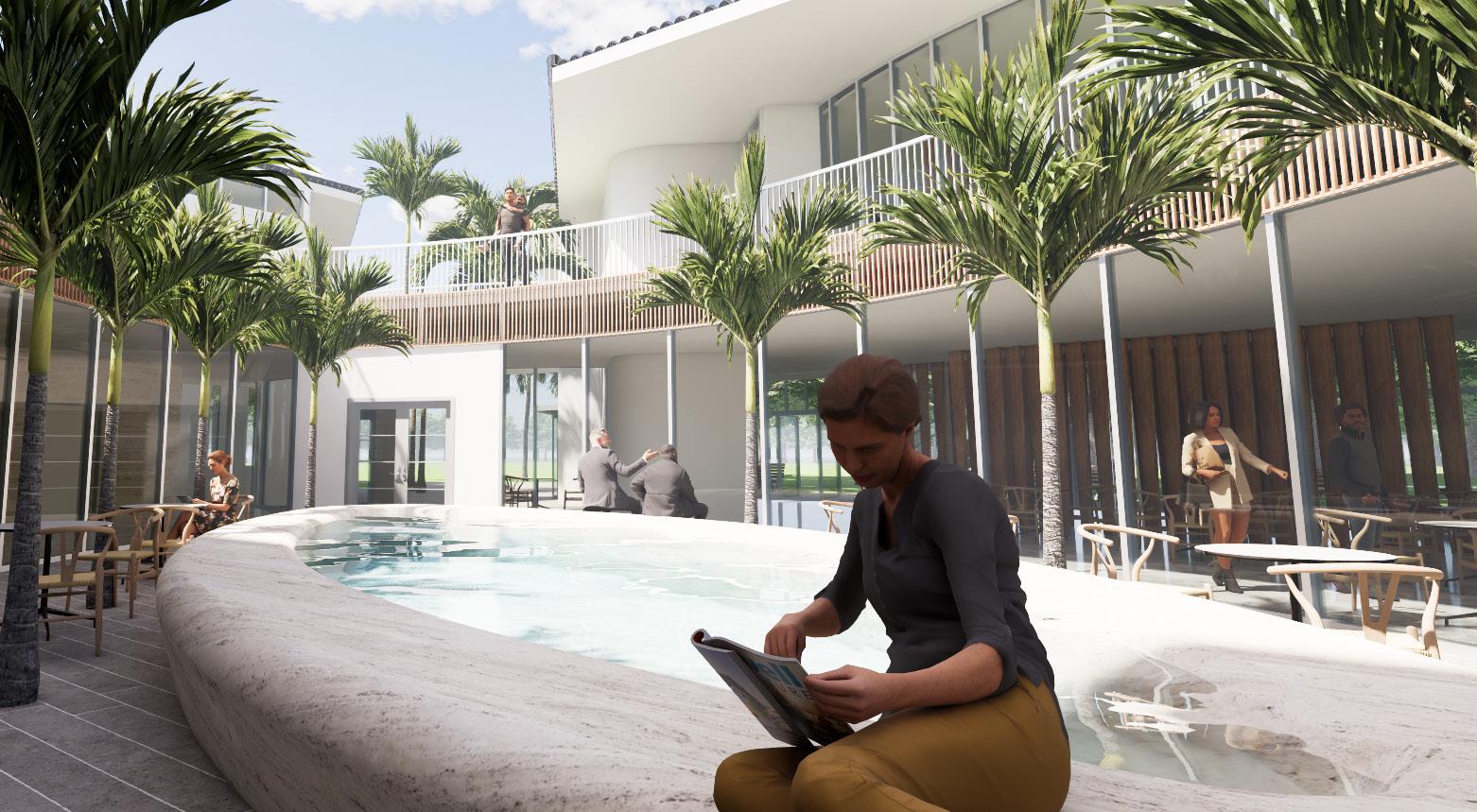
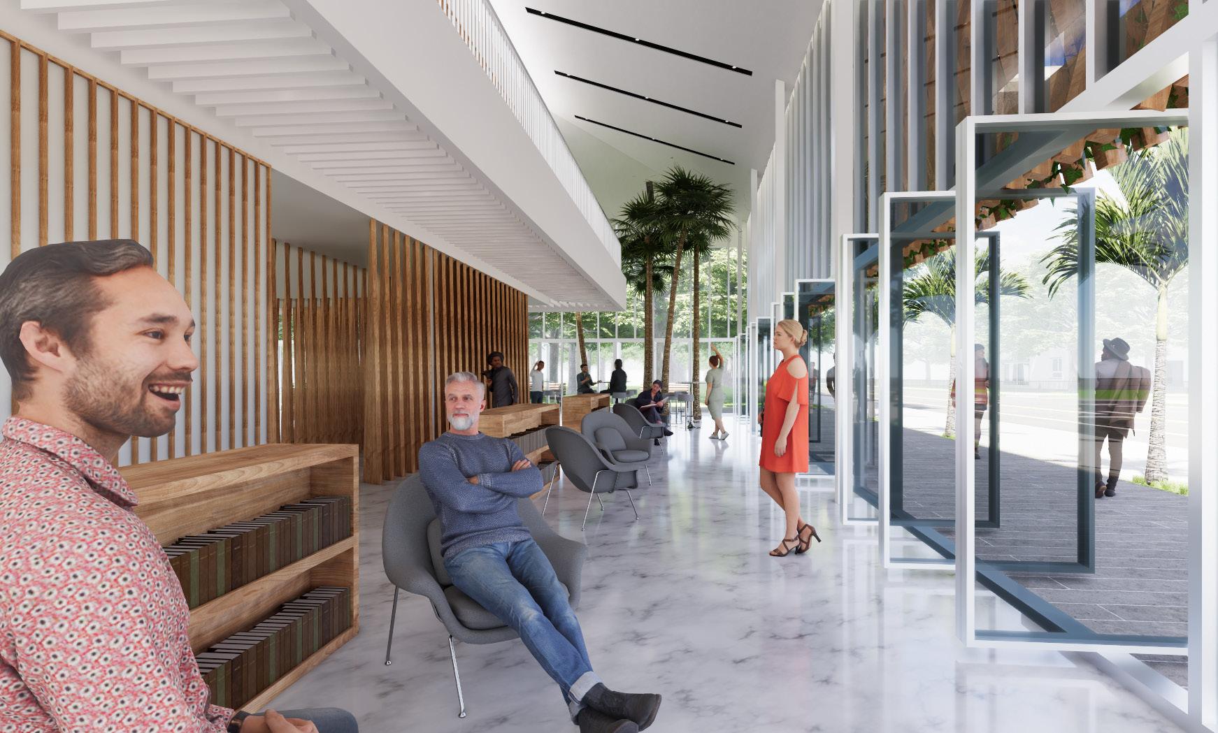
Located on the southeast corner of the Shenandoah Park, itself situated within a dense residential area, the Shenandoah Library strives to act as a community hub. It takes advantage of its central location to form a gateway to the park that offers study, social, and relaxation space. These spaces are supplemented by outdoor gathering space, leveraging Miami’s warm climate. Weaving together inspiration from its residential context, the building’s design is a modern adaptation of Mediterranean architecture, reflecting and enhancing the vernacular to express a good sense of place.

The form of the building is rooted in the theme of embrace. The library is designed around two wings: one being studious (blue) and the other sociable (green). In between these wings is an outdoor oasis, centered around a water feature intended to reflect the calm of their embrace. At the same time, this layout creates a diagonal passage which embraces the neighborhood, drawing it directly into the building’s heart.
floor plan
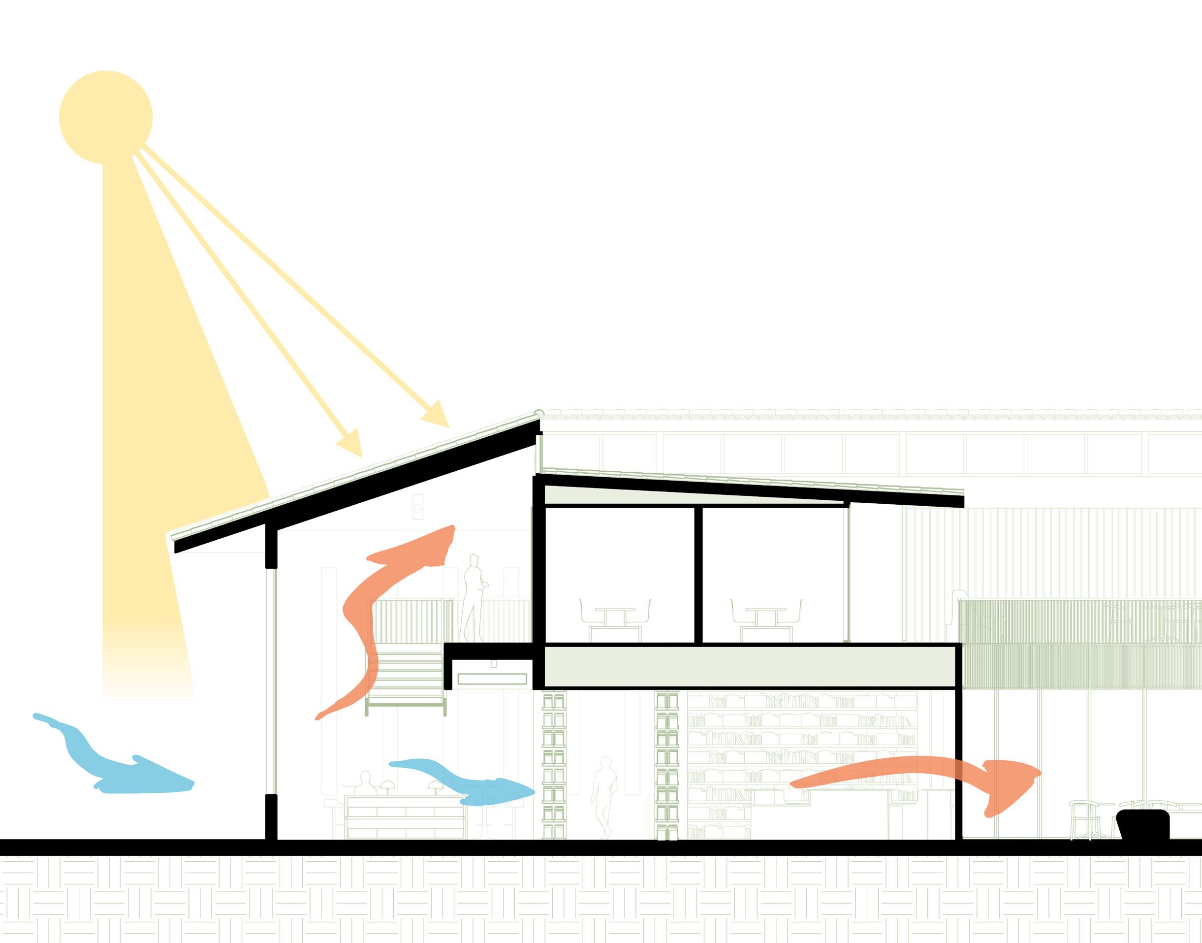
Architectural Design IV at Worcester Polytechnic Institute is focused on energy simulation. From the start, the goal for this building was to operate with net-zero carbon emissions. Through a combination of integrated passive strategies and energy-minimizing active strategies, an annual energy use intensity (EUI) of -0.39 kBtu/ft2 was attained.
Transportation — Internship Project (2024)
Location • New York, NY, USA
Supervisor • Michael Kraft
Responsibilities • Graphic Development | Stakeholder Coordination | Material & Form Studies | Conceptual Design
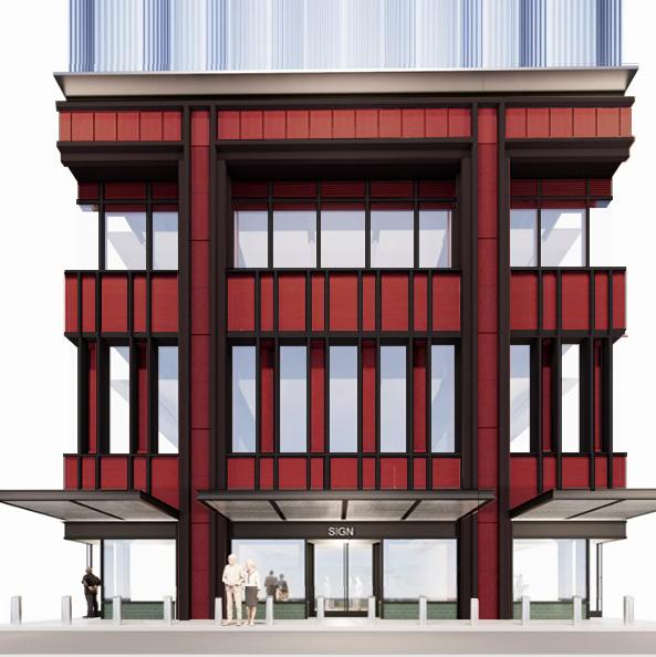
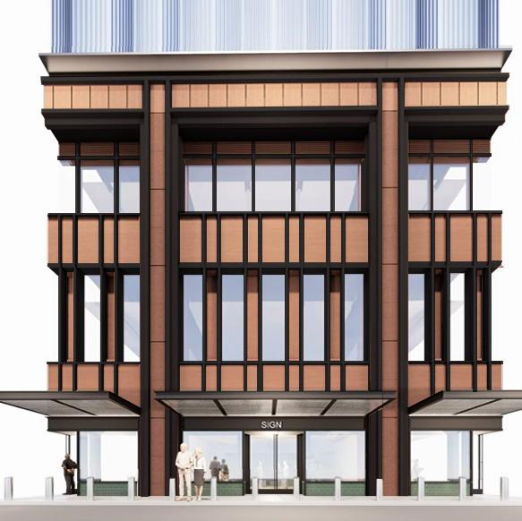
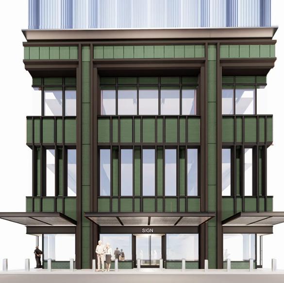
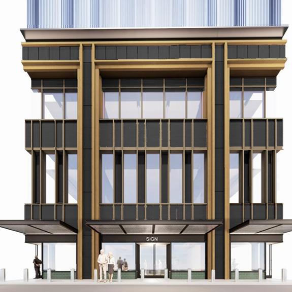
During my summer internship at the Port Authority of New York & New Jersey’s Major Capital Projects department, I had the privilege of working with the Stakeholder Relations group’s design team to coordinate the Midtown Bus Terminal Redevelopment. This $10 billion project will replace the existing Port Authority Bus Terminal, transforming the fabric of Midtown Manhattan in the process. Our team worked with architects from Foster + Partners and Kohn Pedersen Fox, engineers from WSP and Thornton Tomasetti, and other stakeholders to progress the design of this project.
Our work focused on Phase 1: the Ramp Structure and Staging & Storage Facility (SSF). We met with the architects and engineers constantly to develop the design from various angles, including operational needs, community input, and cost minimization. Internally, we met as a team between meetings in a studio-style review of the most recent changes and devised our own solutions to present to the designers.
I made extensive use of Photoshop to aid in the production of these solutions, using it to refine site photos, and create renders of our own. Through this process, we guided stakeholder-driven planning adjustments across the project, community-oriented refinements to the SSF’s facade, and value engineering strategies on the Ramp Structure which optimized their cladding and enhanced their appearance.
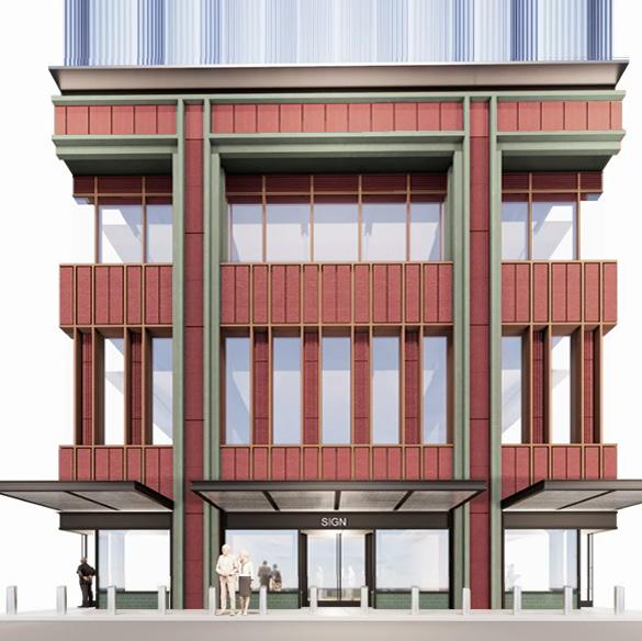
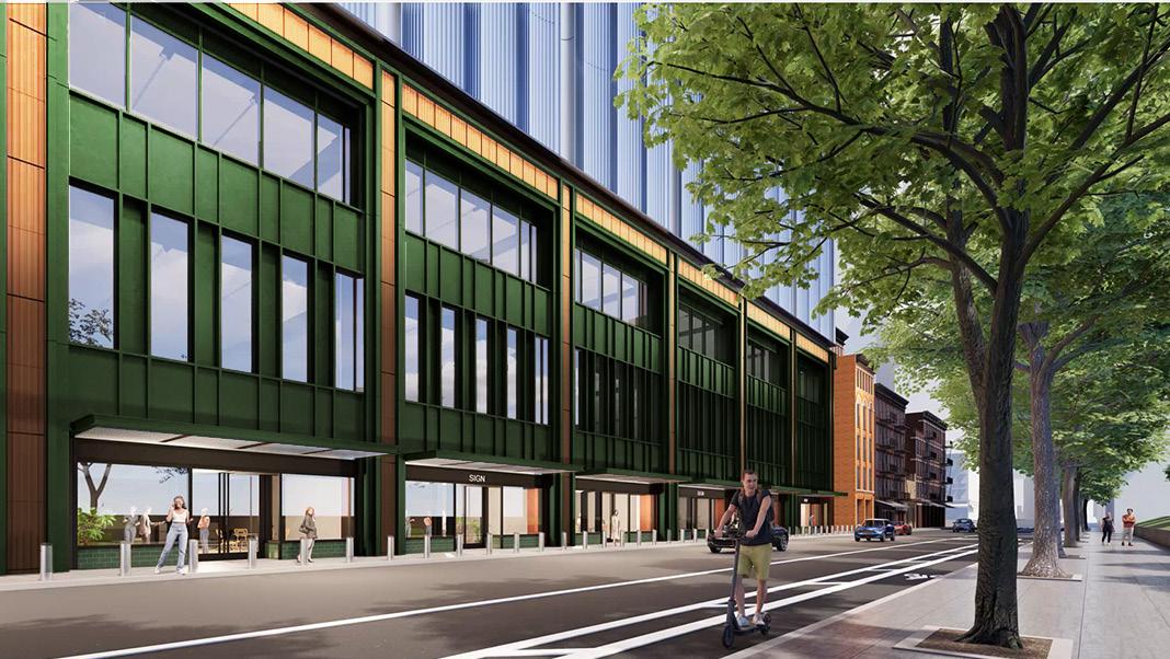
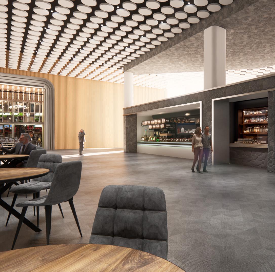
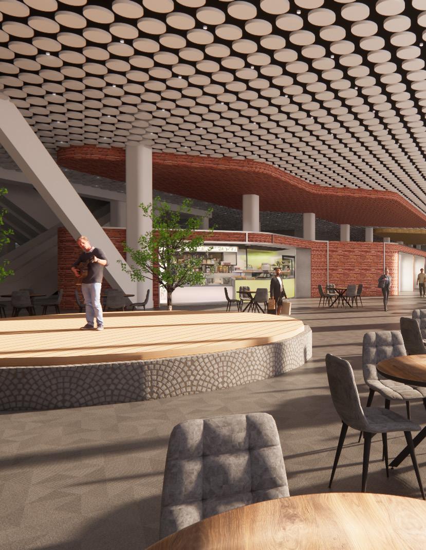
My work culminated in the design of a dining hall scheme for the permanent bus terminal, to be built in phase 2. The dining hall is designed to suit the needs of commuters who need to grab a quick bite to eat, as well as intercity travelers who have more time to linger. As such, guests navigate multiple paths through the space based on their needs, with a diverse array of food outlets set up in a street market style around them. Program inspiration is derived from the terminal’s proximity to the Paddy’s Market Historical District, while circular ceiling panels are designed to be material-efficient by reusing materials from a temporary bus terminal headhouse.
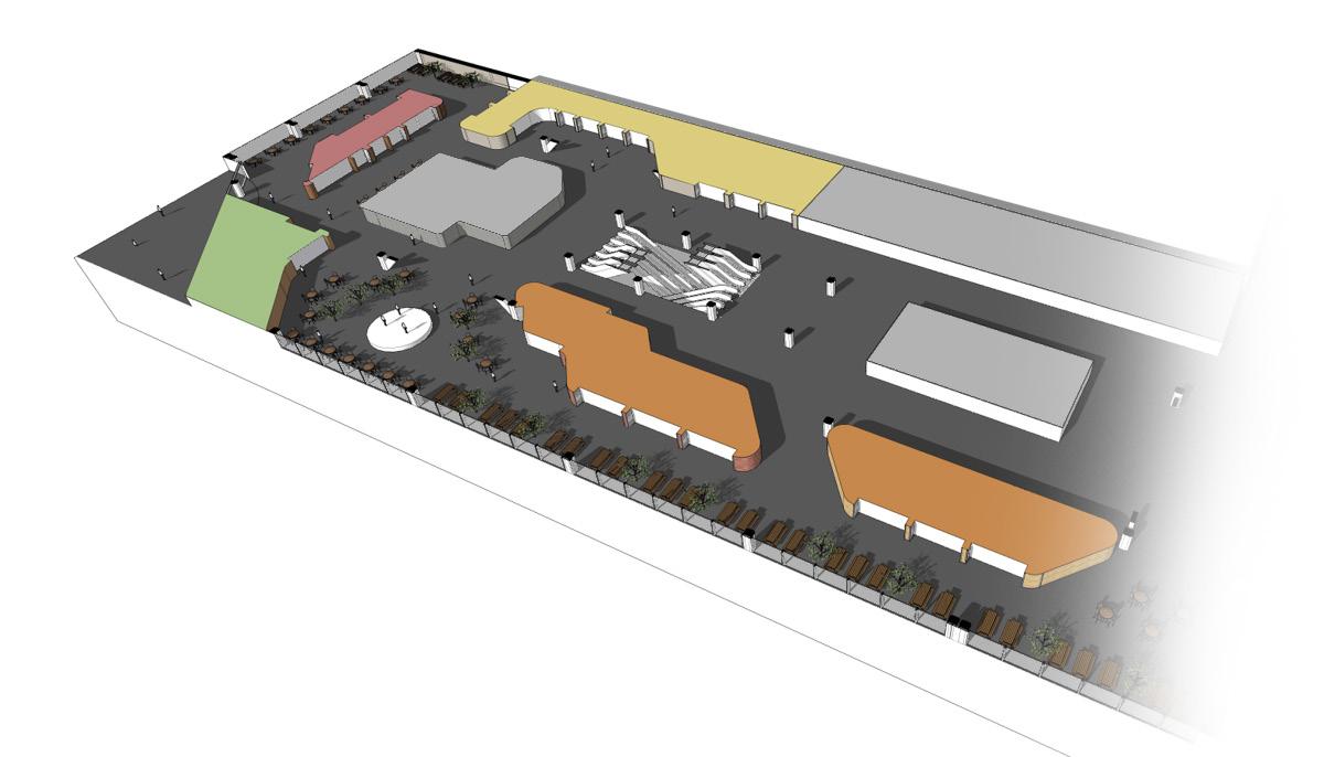
dining experience
Grab-and-go cafes
Full-service food stalls
Locally-inspired market
Axonometric plan rendering of the chosen dining hall scheme