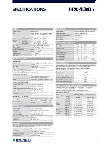
SPECIFICATIONS
ENGINE
SWING SYSTEM
Maker / Model
Cummins QSL9
Swing motor
Fixed displacement axial piston motor
Type
Water cooled, 4 cycle Diesel, 6-cylinders in line, Direct injection, Turbocharged, Charger air cooled, Low emission
Swing reduction
Planetary gear reduction
Swing bearing lubrication
Grease-bathed
Swing brake
Multi wet disc
Swing speed
9.2 rpm
Rated flywheel horse power
SAE DIN
J1995 (gross)
277 kW (372 HP) at 1,800 rpm
J1349 (net)
267 kW (358 HP) at 1,800 rpm
6271/1 (gross)
277 kW (377 PS) at 1,800 rpm
6271/1 (net)
267 kW (363 PS) at 1,800 rpm
Max. torque
166 kgf·m (1,186 lbf·ft) at 1,500 rpm
Bore × stroke
114 × 145 mm (4.5’’ × 5.7’’)
Piston displacement
8,900 cc (543 cu in)
Batteries
2 × 12 V × 160 Ah
Starting motor
24 V - 7.8 kW
Alternator
24 V - 95 A
HYDRAULIC SYSTEM MAIN PUMP Type
Variable displacement tandem axis piston pumps
Max. flow
2 × 333 ℓ/min (88.0 U.S. gpm / 73.2 U.K. gpm)
Sub-pump for pilot circuit
Gear pump
Cross-sensing and fuel saving pump system
SERVICE REFILL CAPACITIES Re-filling
Liter
US gal
Fuel tank
600
159
132
Engine coolant
55
14.5
12.1 6.6
Engine oil
30
7.9
Swing device (each)
8
2.1
1.8
Final drive (each)
12
3.2
2.6
Hydraulic system (including tank)
414
109.7
91.1
Hydraulic tank
210
55.5
41.8
UNDERCARRIAGE The X-leg type center frame is integrally welded with reinforced box-section track frames. The undercarriage includes lubricated rollers, idlers, track adjusters with shock absorbing springs and sprockets and a track chain with double or triple grouser shoes. Center frame
X - leg type
Track frame
HYDRAULIC MOTORS
Pentagonal box type
Travel
Two speed axial pistons motor with brake valve and parking brake
No. of shoes on each side
53 EA
No. of carrier roller on each side
2 EA
Swing
Axial piston motor with automatic brake
No. of track roller on each side
9 EA
No. of rail guard on each side
2 EA
RELIEF VALVE SETTING Implement circuits
330 kgf/cm (4,690 psi)
Travel
360 kgf/cm2 (5,120 psi)
2
Power boost (boom, arm, bucket) 360 kgf/cm2 (5,120 psi) Swing circuit
290 kgf/cm (4,125 psi)
Pilot circuit
40 kgf/cm2 (569 psi)
Service valve
Installed
2
HYDRAULIC CYLINDERS No. of cylinder bore × stroke
Boom: Ø 2-160 × 1,500 mm (6.3’’ x 59.1’’)
DRIVES & BRAKES Drive method
OPERATING WEIGHT (APPROXIMATE) Operating weight, including 6,500 mm (21’ 4’’) boom, 3,200 mm (10’ 6’’) arm, SAE heaped 1.9 m3 (2.49 yd3) Rock bucket, lubricant, coolant, full fuel tank, full hydraulic tank, and all standard equipments.
OPERATING WEIGHT Shoes Type
Arm: Ø 1-170 × 1,760 mm (6.7’’ x 69.3’’) Bucket: Ø 1-150 × 1,295 mm (5.9’’ x 51.0’’)
Fully hydrostatic type
Drive motor
Axial piston motor, in-shoe design
Reduction system
Planetary reduction gear
Max. drawbar pull
33,500 kgf (73,854 lbf)
Max. travel speed (high / low)
5.3 km/hr (3.3 mph) / 3.0 km/hr (1.9 mph)
Gradeability
35° (70%)
Parking brake
Multi wet disc
UK gal
Triple grouser
Operating weight
Ground pressure
Width mm (in)
kg (lb)
kgf/cm2 (psi)
600 (24’’)
44,120 (97,270)
0.76 (10.81)
700 (28’’)
44,640 (98,410)
0.66 (9.39)
750 (30’’)
44,900 (98,990)
0.62 (8.82) 0.59 (8.39)
800 (32’’)
45,170 (99,580)
900 (36’’)
45,680 (100,710)
0.53 (7.54)
Triple grouser (Heavy duty)
600 (24’’)
44,300 (97,660)
0.77 (10.95)
700 (28’’)
44,850 (98,880)
0.67 (9.53)
Double grouser
600 (24’’)
43,930 (96,850)
0.76 (10.81)
700 (28’’)
44,050 (97,110)
0.60 (9.39)
CONTROL Pilot pressure operated joysticks and pedals with detachable lever provide almost effortless and fatigueless operation. Pilot control
Two joysticks with one safety lever (LH): Swing and arm (RH): Boom and bucket (ISO)
Traveling and steering
Two levers with pedals
Engine throttle
Electric, Dial type
1
BUCKET SELECTION GUIDE & DIGGING FORCE BUCKETS
1.90 (2.49) 2.10 (2.75)
SAE heaped m3 (yd3)
Recommendation mm (ft.in)
Capacity m3 (yd3) SAE heaped
CECE heaped
Width mm (in)
Weight kg (lb)
1.90 (2.49)
1.65 (2.16)
1,665 (66’’)
1,980 (4,370)
2 .10 (2.75
1.84 (2.41)
1,800 (71’’)
2,080 (4,590)
6,500 (21’ 4’’) Boom 2,600 (8’ 6’’) Arm
3,200 (10’ 6’’) Arm
: Applicable for materials with density of 2,000 kg /m3 (3,370 lb/ yd3) or less : Applicable for materials with density of 1,600 kg /m3 (2,700 lb/ yd3) or less : Applicable for materials with density of 1,100 kg /m3 (1,850 lb/ yd3) or less
Rock-Heavy duty bucket
ATTACHMENT Booms and arms are welded with a low-stress, full-box section design. 6.5 m & 10.2 m Booms and 2.1 m; 2.5 m; 3.05 m; 3.75 m & 7.85 m. Arms are available.
DIGGING FORCE Arm
Bucket digging force
Length
mm (ft.in)
2,600 (8’ 6’’)
3,200 (10’ 6’’)
Weight
kg (lb)
1,990 (4,390)
2,080 (4,590)
kN
201.0 [219.3]
201.0 [219.3]
SAE
kgf
20,500 [22,360]
20,500 [22,360] 45,190 [49,300]
ISO
Arm crowd force
SAE
ISO
lbf
45,190 [49,300]
kN
228.5 [249.3]
228.5 [249.3]
kgf
23,300 [25,420]
23,300 [25,420]
lbf
51,370 [56,040]
51,370 [56,040]
kN
180.7 [197.2]
160.8 [175.4]
kgf
18,430 [20,110]
16,400 [17,890] 36,160 [39,440]
lbf
40,630 [44,330]
kN
188.0 [205.1]
165.7 [180.8]
kgf
19,170 [20,910]
16,900 [18,440]
lbf
42,260 [46,100]
37,260 [40,650]
Remarks:
[ ]: Power Boost
Note : Boom weight includes arm cylinder, piping, and pin Arm weight includes bucket cylinder, linkage, and pin
2
DIMENSIONS & WORKING RANGE HX430 L DIMENSIONS 6.5 m (21’ 4’’) BOOM and 2.6 m (8’ 6’’); 3.2 m (10’ 6’’) ARM D (D')
E
I
K
F
C
G
A
H
B
L
J
A
Tumbler distance
4,470 (14’ 8’’)
B
Overall length of crawler
5,462 (17’ 11’’)
C
Ground clearance of counterweight
1,295 (4’ 3’’)
D
Tail swing radius
3,615 (11’ 10’’)
D’ Rear-end length
3,555 (11’ 8’’)
E
Overall width of upperstructure
3,095 (10’ 2’’)
F
Overall height of cab
3,240 (10’ 8’’)
G
Min. ground clearance
H
Track gauge
2,740 (9’ 00’’)
I
Overall height of guardrail
3,445 (11’ 4’’)
Arm length
2,600 (8’ 6’’)
3,200 (10’ 6’’)
Overall length
11,270 (37’ 0’’)
11,400 (37’ 5’’)
3,740 (12’ 3’’)
3,630 (11’ 11’’)
K Overall height of boom
565 (1’ 10’’) L
Unit : mm (ft·in)
6,550 (21’ 4’’)
Boom length
J
M
Track shoe width
M Overall width
600 (24’’)
700 (28’’)
750 (30’’)
800 (32’’)
900 (36’’)
3,340 (10’ 11’’)
3,440 (11’ 3’’)
3,490 (11’ 5’’)
3,540 (11’ 7’’)
3,640 (11’ 11’’)
HX430 L WORKING RANGE Unit : mm (ft·in)
A A'
2,600 (8’ 6’’)
3,200 (10’ 6’’)
A Max. digging reach
10,750 (35’ 3’’)
11,160 (36’ 7’’)
A’ Max. digging reach on ground
10,520 (34’ 6’’)
10,930 (35’ 10’’)
B
6,910 (22’ 8’’)
7,500 (24’ 7’’)
B’ Max. digging depth (8ft level)
6,730 (22’ 1’’)
7,350 (24’ 1’’)
C
5,100 (16’ 9’’)
5,440 (17’ 10’’)
D Max. digging height
10,390 (34’ 1’’)
10,290 (33’ 9’’)
E
Max. dumping height
7,250 (23’ 9’’)
7,200 (23’ 7’’)
F
Min. swing radius
4,540 (14’ 11’’)
4,490 (14’ 9’’)
Arm length
D E
B
B' C
8ft
6,500 (21’ 4’’)
Boom length
F
Max. digging depth
Max. vertical wall digging depth
3
LIFTING CAPACITY
Rating over-front
Rating over-side or 360 degrees
HX430 L 6.5 m (21’ 4’’) boom; 2.6 m (8’ 6’’) arm equipped with 2.10 m3 (SAE heaped) bucket and 600 mm (24’’) triple grouser shoes. Load point height m (ft) 9.0 m (30 ft) 7.5 m (25 ft) 6.0 m (20 ft) 4.5 m (15 ft) 3.0 m (10 ft) 1.5 m (5 ft) Ground Line -1.5 m (-5 ft) -3.0 m (-10 ft) -4.5 m (-15 ft)
kg lb kg lb kg lb kg lb kg lb kg lb kg lb kg lb kg lb kg lb
3.0 m (10 ft)
4.5 m (15 ft)
Load radius
6.0 m (20 ft)
At max. reach Capacity
7.5 m (25 ft)
Reach m (ft)
*18230 *40190 *21990 *48480 *17990 *39660
*18230 *40190 *21990 *48480 *17990 *39660
*11000 *24250 *14280 *31480 *16530 *36440 *17270 *38070 *16960 *37390 *15720 *34660 *13070 *28810
*11000 *24250 *14280 *31480 15120 33330 14740 32500 14720 32450 14940 32940 *13070 *28810
*7120 *15700 *8440 *18610 *10020 *22090 *11380 *25090 *12190 *26870 *12320 *27160 *11590 *25550
*7120 *15700 *8440 *18610 *10020 *22090 9660 21300 9310 20530 9190 20260 9290 20480
*6600 *14550 *7210 *15900 *8020 *17680 *8800 *19400 *9320 *20550 *9370 *20660
*6600 *14550 *7210 *15900 7050 15540 6730 14840 6510 14350 6430 14180
*6110 *13470 *6020 *13270 *6110 *13470 *6270 *13820 *6500 *14330 *6770 *14930 *7070 *15590 *7360 *16230 *7530 *16600 *7190 *15850
*6110 *13470 *6020 *13270 5360 11820 4660 10270 4310 9500 4240 9350 4450 9810 5020 11070 6250 13780 *7190 *15850
6.70 (22.0) 8.02 (26.3) 8.86 (29.1) 9.37 (30.7) 9.59 (31.5) 9.56 (31.4) 9.27 (30.4) 8.68 (28.5) 7.73 (25.4) 6.24 (20.5)
6.5 m (21’ 4’’) boom; 3.2 m (10’ 6’’) arm equipped with 1.90 m3 (SAE heaped) bucket and 600 mm (24’’) triple grouser shoes. Load point height m (ft) 9.0 m (30 ft) 7.5 m (25 ft) 6.0 m (20 ft) 4.5 m (15 ft) 3.0 m (10 ft) 1.5 m (5 ft) Ground Line -1.5 m (-5 ft) -3.0 m (-10 ft) -4.5 m (-15 ft)
kg lb kg lb kg lb kg lb kg lb kg lb kg lb kg lb kg lb kg lb
1.5 m (5 ft)
3.0 m (10 ft)
Load radius 4.5 m (15 ft) 6.0 m (20 ft)
7.5 m (25 ft)
9.0 m (30 ft)
At max. reach Capacity Reach m (ft)
*12890 *28420 *13760 *13760 *17830 *30340 *30340 *39310 *18570 *18570 *23870 *40940 *40940 *52620 *24270 *24270 *20790 *53510 *53510 *45830
*12890 *28420 *17830 *39310 *23870 *52620 *20790 *45830
*12950 *28550 *15710 *34630 *17110 *37720 *17340 *38230 *16570 *36530 *14620 *32230
*12950 *28550 15610 34410 14960 32980 14770 32560 14860 32760 *14620 *32230
1. Lifting capacity are based on SAE J1097 and ISO 10567. 2. Lifting capacity of the ROBEX series does not exceed 75% of tipping load with the machine on firm, level ground or 87% of full hydraulic capacity.
*7670 *7670 *16910 *16910 *9350 *9350 *20610 *20610 *10910 9940 *24050 21910 *11990 9480 *26430 20900 12430 9270 *27400 20440 *12110 9270 *26700 20440 *10670 9500 *23520 20940
*5330 *5330 *11750 *11750 *6000 *6000 *13230 *13230 *6690 *6690 *5290 *5290 *14750 *14750 *11660 *11660 *7600 7290 *6650 5220 *16760 16070 *14660 11510 *8500 6920 *7140 5020 *18740 15260 *15740 11070 *9200 6640 *7490 4880 *20280 14640 *16510 10760 *9490 6490 *20920 14310 *9150 6510 *20170 14350
*5440 *5440 *11990 *11990 *5490 *5490 *12100 *12100 *5630 5080 *12410 11200 *5850 4450 *12900 9810 *6110 4130 *13470 9110 *6420 4040 *14150 8910 *6770 4190 *14930 9240 *7150 4640 *15760 10230 *7520 5610 *16580 12370 *7700 *7700 *16980 *16980
7.31 (24.0) 8.53 (28.0) 9.32 (30.6) 9.80 (32.2) 10.01 (32.8) 9.98 (32.7) 9.70 (31.8) 9.15 (30.0) 8.26 (27.1) 6.89 (22.6)
3. The load point is a hook located on the back of the bucket. 4. (*) indicates load limited by hydraulic capacity.
4
ENGINE
STD OPT
Cummins QSL 9 engine
HYDRAULIC SYSTEM Intelligent Power Control (IPC) 3-power mode, 2-work mode, user mode Variable Power Control Pump Flow Control Attachment Mode Flow Control Engine Auto Idle Engine Auto Shutdown Control Electronic Fan Control
CABIN & INTERIOR ISO Standard cabin Rise-up type windshield wiper Radio / USB player Handsfree mobile phone system with USB 12 volt power outlet (24V DC to 12V DC converter) Electric horn All-weather steel cab with 360° visibility Safety glass windows Sliding fold-in front window Sliding side window (LH) Lockable door Hot & cool box Storage compartment & Ashtray Transparent cabin roof-cover Sun visor Door and cab locks, one key Mechanical suspension seat with heater Pilot-operated slidable joystick Console box height adjust system Automatic climate control Air conditioner & heater Defroster Starting Aid (air grid heater) for cold weather Centralized monitoring 8’’ LCD display Engine speed or Trip meter/Accel. Engine coolant temperature gauge Max power Low speed/High speed Auto idle Overload Check Engine Air cleaner clogging Indicators ECO Gauges Fuel level gauge Hyd. oil temperature gauge Fuel warmer Warnings Communication error Low battery Clock Cabin lights Cabin front window rain guard Cabin roof-steel cover Seat Adjustable air suspension seat with heater Cabin FOPS/FOG FOPS (Falling Object Protective Structure) · ISO 3449 Level 2 FOG (Falling Object Guard)· Front & Top Guard Top Guard ISO/DIS 10262 Level 2 Cabin ROPS (ISO 12117-2) ROPS (Roll Over Protective Structure) · ISO 12117-2
SAFETY
STD OPT
Battery master switch Rearview camera AAVM (Advanced Around View Monitoring) Six front working lights Travel alarm Rear work lamp Beacon lamp Automatic swing brake Boom holding system Arm holding system Safety lock valve for boom cylinder with overload warning device Safety lock valve for arm cylinder Swing Lock System Three outside rearview mirrors
OTHER Booms 6.5 m; 21’ 4’’ Arms 2.6 m; 8’ 6’’ 3.2 m; 10’ 6’’ Removable clean-out dust net for cooler Removable reservoir tank Fuel pre-filter with single warmer Fuel pre-filter with dual warmer Self-diagnostics system Hi-mate (Remote Management System) Batteries (2 × 12 V × 160 Ah) Fuel filler pump (50 ℓ/min) Single-acting piping kit (breaker, etc.) Double-acting piping kit (clamshell, etc.) Rotating Piping Kit Quick coupler piping Quick coupler Boom floating control One Pedal Straight Travel System Accumulator for lowering work equipment Pattern change valve (2 patterns) Tool kit
Mobile Satellite
UNDERCARRIAGE Lower frame under cover (Additional) Lower frame under cover (Normal) Track shoes Triple grouser shoes (600 mm; 24’’) Triple grouser shoes (700 mm; 28’’) Triple grouser shoes (750 mm; 30’’) Triple grousers shoe (800 mm; 32’’) Triple grousers shoe (900 mm; 36’’) Triple grousers shoes (600 mm; 24’’ - Heavy Duty) Triple grousers shoes (700 mm; 28’’ - Heavy Duty) Double grousers shoe (600 mm; 24’’) Double grousers shoe (700 mm; 28’’) Track rail guard Full track rail guard high walker STD = Standard OPT = Optional * Standard and optional equipment may vary. Contact your Hyundai dealer for more information. The machine may vary according to International standards. * The photos may include attachments and optional equipment that are not available in your area. * Materials and specifications are subject to change without advance notice. * All imperial measurements rounded off to the nearest pound or inch.
PLEASE CONTACT
Hyundai Heavy Industries Europe N.V. VOSSENDAAL 11, 2440 GEEL, BELGIUM TEL: (32)14-56-2200 FAX: (32)14-59-3405
www.hyundai.eu
EN - 2016.08 Rev 0