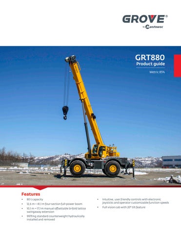
GRT880 Product guide
Metric 85%
Features •
80 t capacity
•
12,6 m – 41,1 m four-section full-power boom
•
10,1 m – 17,1 m manual offsettable bi-fold lattice swingaway extension
•
9979 kg standard counterweight hydraulically installed and removed
•
Intuitive, user friendly controls with electronic joysticks and operator customizable function speeds
•
Full vision cab with 20° tilt feature
GROVE GRT880 The GRT880 was designed after gathering feedback from crane owners and operators to ensure that it is loaded with the features and reliability you demand.
Features Cab The cab is designed with operator comfort and productivity in mind with full-vision design and 20° tilt for improved viewing at high boom angles. The tilt/telescoping steering wheel can be positioned for optimum use.
Control system The new Crane Control System (CCS) offers a user-friendly interface, two full graphic displays mounted vertically for easier viewing and a jog dial for easier navigation and data input. The system allows the electronic controllers to be reprogrammed by the operator for specific speed and reaction. Parts commonality across Grove, Manitowoc and Potain product lines enhances operator familiarization and serviceability.
Boom Lifting performance is enhanced by the 12,6 m – 41,1 m four-section, full-power boom with sequenced, synchronized extension capability.
CraneSTAR is an exclusive and innovative crane asset management system that helps improve your profitability and reduce costs by remotely monitoring critical crane data. Visit www.cranestar.com for more information.
GRT880 benefits Higher nominal capacity and stronger load charts ensure higher rental rates. Outstanding height and reach provide higher utilization and greater versatility. The GRT880 transports to the jobsite quickly and efficiently with a weight under 41,1 t after removal of counterweight and boom extension. Counterweight is hydraulically self-removable and installed by the crane. ECO mode for intelligent power management and decreased fuel consumption.
Manitowoc Crane Care when you need it.
The assurance of the world’s most advanced crane service and support to get you back to work fast.
Manitowoc Finance helps you get right to work generating profits for your business.
Financial tools that help you capitalize on opportunity with solutions that fit your needs.
Contents Working Range Subhead
Dimensions ..................................................................................................................................................................... 5 Weights .......................................................................................................................................................................... 6 Working range................................................................................................................................................................. 7 Load charts ..................................................................................................................................................................... 8 Data ............................................................................................................................................................................... 13 Specifications................................................................................................................................................................... 14 Symbols glossary.............................................................................................................................................................. 16
4
Dimensions
Tire Size: 29.5 x 25 A
B
C
D
E
F
G
A
B
C
D
E
F
G
17,4 m
16,7 m
13,6 m
12,9 m
12,5 m
10,1 m
8,8 m
13,2 m
12,5 m
8,4 m
7,7 m
7,3 m
4,9 m
4,6 m
Two-Wheel Steer
Four -Wheel Steer
Dimensions in mm unless otherwise specified.
OF ROTATION
3335
A 24°
24° B
C
D OUTSIDE CURB CLEARANCE
E OUTSIDE TURN RADIUS
F INSIDE TURN RADIUS
G INSIDE CURB RADIUS
R4568 TAIL SWING
15 114 20° CAB TILT
1121
3746
25°
21° 551 2307
556
8590
4215
14 875
2544 TRACK 3150 RETRACTED 5233 MID-EXTEND 7316 FULL EXTEND
Grove GRT880
5
Weights
Weights
Basic Machine (T4F): including 41,1 m main boom, main hoist with 213,9 m of wire rope, 10 t full counterweight, 75 t hookblock, 11,0 t headache ball, auxiliary boom nose, and air conditioning Add: auxiliary hoist crane weight Add: manual offsettable bui-fold swingaway and brackets crane weight Remove: counterweight crane weight Remove: manual bi-fold extension crane weight
kg
kg
kg
50 500
24 626
25 875
488
157
-605
50 948
24 469
26 480
1502
2797
-1295
52 451
27 266
25 184
-10 000
3735
-13 735
42 459
31 001
11 449
-1324
-2508
1184
41 127
28 493
12 633
THIS CHART IS ONLY A GUIDE AND SHOULD NOT BE USED TO OPERATE THE CRANE. The individual crane’s load chart, operating instructions and other instructional plates must be read and understood prior to operating the crane
6
Data
H
Lifting Capacity
Sheaves
Parts of line
Total weight
91 t
6
2 to 12
672 kg
81,5 t
5
2 to 10
602 kg
60 t
5
2 to 10
580 kg
45 t
3
2 to 6
455 kg
22,5 t
1
2
300 kg
10,9 t
H/B (swivel)
1
255 kg
+
Infinitely variable
Rope
Permissible line pull max.
Nominal cable length
0 - 148 m/min
single line
19 mm (35x7 WSC)
7620 kg
214 m
0 - 148 m/min
single line
19 mm (35x7 WSC)
7620 kg
214 m
—
—
—
0 - 2,0
20° 70°
approx.45 s
—
—
—
11,8 to 46,9 m
approx. 160 s
—
—
—
THIS CHART IS ONLY A GUIDE AND SHOULD NOT BE USED TO OPERATE THE CRANE. The individual crane’s load chart, operating instructions and other instructional plates must be read and understood prior to operating the crane
Grove GRT880
7
Working range Working range diagram with bi-fold extension and insert Working range diagram with insert and bi-fold extension (BOOM DEFLECTION NOT SHOWN)
80089455
75 70
20° OFFSET
0° OFFSET
17,1 M EXT
65 60
40° OFFSET
45 41,1
40
37,9
35
70°
80°
31,6
60°
30
28,4
50°
25
25,2
40°
20
34,7
22,1 18,9
30°
15,7
15
12,6
20°
10
Boom and extension length in meters
Height from ground in meters
55
80° MAX BOOM ANGLE
10°
5 0 65
60
55
50
45
40
35
30
25
20
15
10
5
0
Operating radius in meters from axis of rotation
2,8
AXIS OF ROTATION
Dimensions are for the largest grove furnished hook block and overhaul ball, with anti-two block activated.
3,0
THIS CHART IS ONLY A GUIDE AND SHOULD NOT BE USED TO OPERATE THE CRANE. The individual crane’s load chart, operating instructions and other instructional plates must be read and understood prior to operating the crane
8
Load chart
12,6 m – 41,1 m
9979 kg
100%
360°
Metric Tons (t)
85%
Main Boom Length in Meters 22,1 25,2 28,4 31,6
Radius in Meters
12,6
15,7
18,9
34,7
37,9
41,1
Radius in Meters
2,5
80,000
—
—
—
—
—
—
—
—
—
2,5
3
73,000
49,425
48,975
*31,450
—
—
—
—
—
—
3
3,5
69,200
49,425
48,975
31,450
*19,150
—
—
—
—
—
3,5
4
65,825
49,425
48,975
31,450
19,150
—
—
—
—
—
4
4,5
62,600
49,425
48,975
31,450
19,150
*19,150
—
—
—
—
4,5
5
57,775
48,800
46,625
31,450
19,150
19,150
*19,100
—
—
—
5
6
48,150
47,300
41,100
31,450
19,150
19,150
19,100
*18,375
—
—
6
7
41,150
40,925
36,775
29,200
19,150
19,150
19,100
18,375
*14,925
—
7
8
35,075
34,875
32,975
26,675
19,150
19,150
18,825
17,925
14,775
10,425
8
9
28,350
29,400
27,525
24,050
19,150
19,150
18,125
16,750
14,400
10,425
9
10
16,600
23,950
23,750
21,900
19,150
18,225
16,875
15,550
13,625
10,425
10
12
—
16,825
16,025
16,550
17,175
15,850
14,500
13,425
12,050
10,425
12
14
—
—
11,900
12,275
12,850
13,425
12,600
11,700
10,750
9,425
14
16
—
—
9,075
9,355
9,955
10,475
10,700
10,275
9,640
8,460
16
18
—
—
—
7,210
7,565
8,355
8,605
8,835
8,560
7,640
18
20
—
—
—
—
6,000
6,715
7,005
7,250
7,545
6,925
20
22
—
—
—
—
4,760
5,415
5,745
6,005
6,270
6,335
22
24
—
—
—
—
—
4,370
4,715
5,005
5,250
5,450
24
26
—
—
—
—
—
3,510
3,715
4,160
4,405
4,600
26
28
—
—
—
—
—
—
3,020
3,445
3,675
3,880
28
30
—
—
—
—
—
—
—
2,825
3,050
3,260
30
32
—
—
—
—
—
—
—
2,295
2,405
2,725
32
34
—
—
—
—
—
—
—
—
1,960
2,260
34
36
—
—
—
—
—
—
—
—
—
1,855
36
38
—
—
—
—
—
—
—
—
—
1,495
38
*This capacity is based on maximum boom angle.
THIS CHART IS ONLY A GUIDE AND SHOULD NOT BE USED TO OPERATE THE CRANE. The individual crane’s load chart, operating instructions and other instructional plates must be read and understood prior to operating the crane
Grove GRT880
9
Load chart
41,1 m
10,1 m – 17,1 m
100%
9979 kg
360°
85%
Metric Tons (t) Radius in Meters
10,1 m Length
17,1 m Length
Radius in Meters
0° Offset
20° Offset
40° Offset
0° Offset
20° Offset
40° Offset
10
6,645
—
—
*3,760
—
—
10
12
6,225
*5,170
—
3,760
—
—
12
14
5,615
4,885
—
3,760
—
—
14
16
5,020
4,515
3,465
3,760
—
—
16
18
4,550
4,130
3,365
3,565
2,850
—
18
20
4,190
3,775
3,280
3,255
2,715
*2,175
20
22
3,815
3,525
3,195
2,980
2,585
2,135
22
24
3,545
3,260
3,120
2,750
2,435
2,135
24
26
3,285
3,035
2,945
2,540
2,275
2,095
26
28
3,045
2,840
2,770
2,325
2,120
2,015
28
30
2,825
2,670
2,605
2,150
1,970
1,875
30
32
2,640
2,495
2,450
2,005
1,835
1,775
32
34
2,350
2,365
2,340
1,850
1,715
1,665
34
36
1,980
2,140
2,215
1,715
1,615
1,570
36
38
1,650
1,785
1,990
1,615
1,515
1,470
38
40
1,360
1,475
1,690
1,495
1,420
1,395
40
42
1,095
1,190
—
1,290
1,335
1,325
42
44
0,860
0,935
—
1,055
1,260
1,255
44
46
0,645
0,695
—
0,845
1,035
—
46
48
—
—
—
0,650
0,820
—
48
50
—
—
—
—
0,625
—
50
*This capacity is based on maximum boom angle. 1.
10,1 m and 17,1 m folding boom extension lengths may be used for single line lifting service only.
2. For main boom lengths less than 41,1 m with the boom extension erected, the rated loads are determined by boom angle. Use only the column which corresponds to the boom extension length and offset for which the machine is set up. For boom angles not shown, use rating of the next lower boom angle. 3. WARNING: Operation of this machine with heavier loads than the capacities listed is strictly prohibited. Machine tipping with boom extension occurs rapidly and without advance warning.
4. Boom angle is the angle above or below horizontal of the longitudinal axis of the boom base section after lifting rated load. 5. Capacities listed are with outriggers properly extended and vertical jacks set only. 6. When lifting over the main boom nose with the 10,1 m or 17,1 m extension erected, the outriggers must be fully extended.
THIS CHART IS ONLY A GUIDE AND SHOULD NOT BE USED TO OPERATE THE CRANE. The individual crane’s load chart, operating instructions and other instructional plates must be read and understood prior to operating the crane
10
Load chart
41,1 m
17,1 m
6,1 m
9979 kg
100%
360°
85%
Metric Tons (t) Radius in Meters
1.
23,2 m Length
Radius in Meters
The 17,1 m folding boom extension lengths may be used for single line lifting service only.
2. For main boom lengths less than 41,1 m with the boom extension erected, the rated loads are determined by boom angle. Use only the column which corresponds to the boom extension length and offset for which the machine is set up. For boom angles not shown, use rating of the next lower boom angle.
0° Offset
20° Offset
40° Offset
14
2,985
—
—
14
16
2,985
—
—
16
18
2,915
*2,195
—
18
20
2,635
2,105
—
20
22
2,365
2,015
*1,530
22
24
2,175
1,930
1,490
24
26
1,980
1,835
1,455
26
5. Capacities listed are with outriggers properly extended and vertical jacks set only.
28
1,805
1,685
1,425
28
30
1,650
1,550
1,395
30
6. When lifting over the main boom nose with the 17,1 m extension erected and 6,1 m insert, the outriggers must be fully extended.
32
1,510
1,425
1,370
32
34
1,385
1,320
1,305
34
36
1,255
1,225
1,205
36
38
1,160
1,120
1,120
38
40
1,060
1,035
1,030
40
42
0,975
0,955
0,960
42
44
0,885
0,880
0,885
44
46
0,825
0,805
0,815
46
48
0,705
0,740
0,750
48
50
0,550
0,680
0,690
50
3. WARNING: Operation of this machine with heavier loads than the capacities listed is strictly prohibited. Machine tipping with boom extension occurs rapidly and without advance warning. 4. Boom angle is the angle above or below horizontal of the longitudinal axis of the boom base section after lifting rated load.
*This capacity is based on maximum boom angle.
THIS CHART IS ONLY A GUIDE AND SHOULD NOT BE USED TO OPERATE THE CRANE. The individual crane’s load chart, operating instructions and other instructional plates must be read and understood prior to operating the crane
Grove GRT880
11
Load chart
12,6 m – 22,1 m
9979 kg
Stationary
Metric Tons (t)
Radius in Meters
1.
85%
Main Boom Length in Meters
Radius in Meters
12,6
15,7
18,9
22,1
4,5
17,900
16,775
—
—
4,5
5
16,150
15,550
—
—
5
6
12,100
11,600
10,975
11,100
6
7
9,375
8,870
8,390
8,610
7
8
7,425
6,870
6,525
6,735
8
9
5,960
5,340
5,115
5,285
9
10
4,810
4,140
4,005
4,130
10
12
—
2,360
2,385
2,400
12
14
—
—
1,255
1,170
14
Capacities are in pounds and do not exceed 75% of tipping loads as determined by test in accordance with SAE J765.
2. Capacities are applicable to machines equipped with General/Titan 29.5 x 25 (34 ply) bias ply tires, at 76 psi cold inflation pressure. 3. Capacities are applicable only with machine on firm level surface 4. On rubber lifting with boom extension not permitted 5. For pick and carry operation, boom must be centered over front of machine, mechanical swing lock engaged and load restrained from swinging. 6. Axle lockouts must be functioning when lifting on rubber. 7.
All lifting depends on proper tire inflation, capacity and condition. Capacities must be reduced for lower tire inflation pressures. See lifting capacity chart for tire used. Damaged tires are hazardous to safe operation of crane.
8. Creep - not over 60,96 m of movement in any 30 minute period and not exceeding 1,6 kph.
THIS CHART IS ONLY A GUIDE AND SHOULD NOT BE USED TO OPERATE THE CRANE. The individual crane’s load chart, operating instructions and other instructional plates must be read and understood prior to operating the crane
12
Load chart
12,6 m – 22,1 m
9979 kg
Over front
Pick and carry up to 1,6 kph
Metric Tons (t)
85%
Main Boom Length in Meters
Radius in Meters
12,6
15,7
18,9
22,1
Radius in Meters
3,5
24,375
20,450
—
—
3,5
4
22,850
20,250
—
—
4
4,5
20,625
19,950
—
—
4,5
5
18,725
18,525
—
—
5
6
15,600
15,425
14,100
11,100
6
7
13,325
13,200
12,850
10,925
7
8
11,275
11,200
11,375
10,475
8
9
9,625
9,580
9,700
9,525
9
10
8,255
8,270
8,345
8,305
10
12
—
5,995
5,995
6,000
12
14
—
—
4,090
4,130
14
16
—
—
2,725
2,795
16
18
—
—
—
1,790
18
THIS CHART IS ONLY A GUIDE AND SHOULD NOT BE USED TO OPERATE THE CRANE. The individual crane’s load chart, operating instructions and other instructional plates must be read and understood prior to operating the crane
Grove GRT880
13
Specifications
Superstructure
Cab
Boom
12,6 m – 41,1 m four-section full-power boom, sequenced synchronized extension and retraction. Maximum tip height: 44,6 m
*Optional manual bi-fold swingaway extension
10,1 m - 17,1 m bi-fold lattice swingaway extension. Offsettable at 0°, 20°, and 40°. Stows alongside base boom section. Electric motor assist for pin alignment and stowing. Maximum tip height: 61,9 m
*Optional lattice extension insert
(1) x 6,1 m lattice extension insert. Installs between boom nose and either optional extension. Maximum tip height: 68,0 m
Operator-controlled 20° hydraulic tilt, full vision, all steel fabricated with acoustical lining and tinted safety glass throughout. Deluxe seat with headrest incorporates armrest-mounted electronic programmable single-axis or dual axis controllers and a jog dial for easier data input. Tilt/telescoping steering wheel with various controls incorporated into the steering column. Other standard features include hot water heater, cab circulating air fan, sliding side and opening rear window, sliding skylight with electric wiper and sunscreen, electric windshield wash/wipe, fire extinguisher, seat belt, air conditioning, and dual cab mounted work lights.
Swing
Boom nose
Variable speed, planetary swing drive with foot applied multi-disc proportional wet brake. Spring applied, hydraulically released swing brake. Two position mechanical swing lock pin, operated from cab. Maximum swing speed: 2.0 r.p.m.
Boom elevation
Planetary reduction driven by axial piston motor. Grooved drum with automatic spring applied multi-disk wet brake. Electronic hoist drum rotation indicator, and hoist drum cable follower. Third wrap indictor with hoist function cut-out standard.
Crane Control System (CCS)
Maximum hoist single line pull: 1st layer: 10 645 kg 3rd layer: 9038 kg 6th layer: 7371 kg
Five nylatron sheaves mounted on heavy-duty tapered roller bearings with removable pin-type guards. Quick-reeve type boom nose. Removable single sheave auxiliary boom nose with removable pin type rope guard.
One double–acting hydraulic cylinder with integral holding valve provides elevation from -3° to +80°.
“Graphic Display” RCL load moment and anti-two block system with audio-visual warning and control lever lockout. This system provides electronic display of boom angle, boom length, load radius, boom tip height, maximum permissible load, actual load, and warning of impending two-block condition. The work area definition system allows the operator to pre-select and define safe working areas. If the crane approaches the pre-set limits, audio-visual warnings aid the operator in avoiding jobsite obstructions.
Counterweight
Standard 9979 kg. Hydraulically installed and removed. Controls located on superstructure.
Hoist (main and auxiliary hoist)
Maximum permissible single line pull: 7620 kg with 35 x 7 class rope Maximum hoist single line speed (no load): 148 m/min Rope construction: 35 x 7 rotation–resistant Rope diameter: 19mm Rope length: Main hoist: 214 m Auxiliary hoist: 214 m Maximum usable rope: 241 m 6 layers
* Denotes optional equipment
14
Specifications Carrier
Steering
Chassis
Parallel box section fabricated from high-strength, low-alloy steel with integral outrigger boxes, front and rear lift, tie-down, and towing lugs.
Outrigger system
Four hydraulic telescoping single stage double box beam outriggers with inverted jack cylinders and integral jack holding valves. Three position settings, 0%, 50%, and fully extended. Aluminum fabricated outrigger floats 609,6 mm (24 in) diameter. Outrigger monitoring system with outrigger beam position display on R.C.L. screen. Maximum outrigger pad load: 57 244 kg
Fully independent power steering. Front: Fully hydraulic steering wheel controlled. Rear: Fully hydraulic via separate momentary switch provides 4 steering modes, front only, rear only, coordinated and crab. Rear steer not aligned indicator. Outside 4WS coordinated steer radius: 7,3 m Inside 4WS coordinated steer radius: 4,9 m
Tires
29.5 x 25 – 34 bias ply rating
Electrical system
Outrigger controls
Two 12 V maintenance-free batteries with disconnect. 24 V system / 24 V lighting
Hydraulic system
Full lighting including turn indicators, head, tail, brake, and hazard warning, and two work lights mounted on cab front.
Controls and crane leveling indicator located in cab. Extension and retraction are through the CCS system.
Lighting
Two main pumps [2] variable displacement piston and [1] gear with a combined output capacity of 496 L/min (131 gal/min). Maximum operating pressure: 276 bar (4000 psi) Return line in-tank filter with full flow by-pass protection and service indicator. Replaceable cartridge with 4 micron filtration rating per ISO cleanliness level of 17/15/12. Carrier mounted oil cooler with thermostatically controlled hydraulic motor driven fan / air to oil. System pressure test ports.
Maximum Drive Speed
24.1 km/h with counterweight installed
Gradeability (theoretical) 70% to drive train stall based on 52 450 kg GVW with 29.5 x 25 tires, standard counterweight, auxiliary hoist and manual bi-fold extension.
Engine (Tier 4F)
Cummins QSB 6.7 L diesel, six cylinder, turbo-charged with Cummins Compact Catalyst (CCC) and Selective Catalytic Reduction (SCR) combo muffler, using diesel exhaust fluid (DEF) injection. Meets emissions per US EPA Tier 4 final and European Union Stage 4. 205 kW at 2500 rpm, Maximum torque: 990 Nm at 1500 rpm. Fuel requirements: Maximum of 15 ppm ultra-low sulfur diesel fuel + diesel exhaust fluid (DEF). NOTE: Required for sale in North America and European Union.
Miscellaneous standard equipment
Full length steel fenders with full aluminum decking, dual rear view mirrors, hook block tie-down, electronic back-up alarm, front stowage tray, hot water cab heater / defroster, cab air conditioner, hoist mirrors, A/V warning system, combination lift/tie-down/towing lugs, coolant sight level indicator, hoist access platform.
*Optional equipment Engine (Tier 3)
• Auxiliary hoist package: includes MTW 19-241 hoist with electronic hoist drum rotation indicator, hoist drum cable follower, third wrap indicator with hoist function cut-out, 214 m of 19 mm of 35 x 7 class rotation resistant wire rope. • Auxiliary lighting and convenience package: includes superstructure mounted amber flashing light, dual base boom mounted floodlights, in-cab, R.C.L., light bar and rubber mat for storage trough.
Fuel tank capacity
• • • • • • • • • • •
Cummins QSB 6.7 L diesel, six cylinder, turbo-charged with 205 kW at 2500 rpm, Maximum torque: 978 Nm at 1500 rpm. Fuel requirements: Maximum of 5000 ppm. Sulfur diesel fuel. NOTE: Required for sale outside of North America and European Union.
312 L
Transmission
Rangeshift with six forward and six reverse speeds. (Three speeds high and three speeds low). Front axle disconnect for 4 x 2 drive.
Axles
FRONT: Drive / steer with differential and planetary reduction hubs rigid mounted to frame. REAR: Drive / steer with differential and planetary reduction hubs pivot mounted to frame. Automatic full hydraulic lockouts on rear axle permits 254 mm (10 in) of oscillation only with boom centered over the front.
• • • • •
360° positive mechanical swing lock Rear pintle hitch Cab-controlled cross axle differential locks (front and rear) Wireless wind speed indicator Vertical external mounted L.M.I. light tower -29C cold weather package -40C arctic weather package Electric drive line retarder Emergency stop buttons on each side of carrier Second beacon light Refinery package (certified spark arrestor + engine air shutdown) (T3 engine only) C.E. certificate package Russian certificate package Synthetic rope for main and / or auxiliary hoist Boom position indicator light Crane STAR asset management system
Brakes
Full hydraulic split (dual) circuit dry disc operating on all wheels with dual calipers. Parking brake is spring applied / hydraulically released on the front axle input shaft.
* Denotes optional equipment
Grove GRT880
15
Symbols Glossary
Axles
Crane control system
Heavy duty jib
Outriggers
Boom
Drive
Height (no max)
Radius
Boom elevation
Electrical system
Hoist
Rotation
Boom extension
Engine
Boom length
16
Extension
H
Hook block
Speed
Hydraulic system
Steering
Boom nose
Frame
Insert
Suspension
Brakes
Fuel tank capacity
Lights
Swing
Cab
Gear
Oil
Tires
Counterweight
Grade
Outrigger controls
Transmission
Notes
Grove GRT880
17
Notes
18
Notes
Grove GRT880
19
Manitowoc Cranes Regional headquarters Americas Manitowoc, Wisconsin, USA Tel: +1 920 684 6621 Fax: +1 920 683 6277
Europe and Africa Dardilly, France - TOWERS Tel: +33 (0)4 72 18 20 20 Fax: +33 (0)4 72 18 20 00
Shady Grove, Pennsylvania, USA Tel: +1 717 597 8121 Fax: +1 717 597 4062
Wilhelmshaven, Germany - MOBILE Tel: +49 (0) 4421 294 0 Fax: +49 (0) 4421 294 4301
China Shanghai, China Tel: +86 21 6457 0066 Fax: +86 21 6457 4955
Middle East and Greater Asia-Pacific Singapore Tel: +65 6264 1188 Fax: +65 6862 4040
Dubai, UAE Tel: +971 4 8862677 Fax: +971 4 8862678/79
This document is non-contractual. Constant improvement and engineering progress make it necessary that we reserve the right to make specification, equipment, and price changes without notice. Illustrations shown may include optional equipment and accessories and may not include all standard equipment.
Š2017 The Manitowoc Company, Inc.
Form No. GRT880 Metric Product Guide 02/2017
www.manitowoc.com