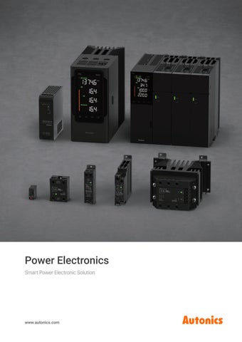
Power Electronics Smart Power Electronic Solution
www.autonics.com Power Electronics
1
CONTENTS
Power Control System
06
Main Features
12
Specifications
26
Applications
38
Autonics, Power Electronics Power control is essential in many aspects of the industry, such as maintaining product quality, improving process efficiency, and saving energy, and it serves as a core element that increases productivity and reliability across the industry.
Such power control systems consist of key components including temperature controllers, power controllers, SSRs, and SMPS, each performing its designated role to stably supply the required power to each device and maintain the optimal output state.
SMPS converts AC voltage into stable DC voltage to provide a reliable power supply throughout the system, while SSRs utilize semiconductor elements to switch the power of loads such as heaters and furnaces rapidly and precisely without mechanical contacts. The temperature controllers compare the target temperature and the current temperature based on the signal received from the temperature sensors, analyze the difference, and send control signals to the power controllers. The power controllers receive these signals and precisely regulate the amount of power supplied to loads through various methods such as phase control, cycle control, and feedback control.
Autonics features a wide lineup of power electronics with various control methods and a broad application range, meeting the demanding requirements of industrial sites. In all environments where precise power control is required, Autonics provides optimal solutions to help customers achieve both process stability and energy efficiency.
4
Autonics
Power Electronics
5
Power Control System
2. SSR
or
3. Power Controller
The SSR receives the control signal from the temperature controller and switches the power at high speed, while the power controller regulates the power supplied to the heater for stable temperature control. The SMPS supplies DC power to the control devices. Temperature Controller
Control Signal
Temperature Feedback
Load Input
Temperature Sensor
Control Power Supply
Load Output
* Not required when SSR using
1. SMPS
Temperature Detection
1. SMPS A device that converts AC voltage into stable DC voltage using a semiconductor switching process, commonly known as a Switching Mode Power Supply (SMPS).
Heater
2. SSR A solid-state relay (SSR) using semiconductor switching elements is widely used for power control such as heaters, and semiconductor equipment drives.
3. Power Controller A device that controls the amount of power required for heating and cooling of heaters, electric furnaces, heat chambers, motors, and other loads. It is widely used in semiconductor equipment that requires precise and stable temperature control.
6
Autonics
Power Electronics
7
SMPS Overview
SSR Overview
Series
SPA
SPB-A
Series
SRH1 (current)
SRH1 (voltage)
SRHL1
SR1
SRC1
Output power
30 W, 50 W, 75 W, 100 W, 400 W
15 W, 30 W, 60 W, 120 W, 240 W, 480 W
Control phase / Heatsink
Single-phase / Integrated heatsink
Single-phase / Integrated heatsink
Single-phase / Integrated heatsink
Single-phase / Detachable heatsink
Single-phase / Detachable heatsink
Input voltage
100 – 240 VAC or 100 – 120 VAC / 200 – 240 VAC
100 – 240 VAC 90 – 350 VDC
Type
Top/bottom terminal
Top/bottom terminal
Alarm output
Slim
Slim
Efficiency (Typical)
≥ 60 % ~ 80 % (Depending on the model)
≥ 70 % ~ 93 % (Depending on the model)
Rated input voltage
-
10 - 30 VDC 90 - 240 VAC
4 - 30 VDC 90 - 240 VAC
4 - 30 VDC 90 - 240 VAC
Start-up time
≤ 250 ms
≤ 990 ms
4 - 30 VDC 24 VAC 90 - 240 VAC
Rated input current
4 -20 mA
-
-
-
-
Hold time
≥ 5 ms
≥ 22 ms
Rated load voltage
Load variation
≤ 2.0 %
≤ 3.0 %
100 - 240 VAC 200 - 480 VAC
24 - 240 VAC 48 - 480 VAC
24 - 240 VAC 48 - 480 VAC
24 - 240 VAC 48 - 480 VAC
24 - 240 VAC 48 - 480 VAC
Rated load current
20 A, 30 A, 60 A
Input variation
≤ 0.5 %
≤ 0.5 %
10 A, 15 A, 20 A, 30 A, 40 10 A, 15 A, 20 A, 25 A, 40 10 A, 15 A, 20 A, 25 A, 30 15 A, 20 A, 30 A A, 60 A A A, 40 A, 50 A, 75 A O
O
DIN Rail
X (Phase Control, Cycle Control)
O
Panel
Zero cross turn-on/ Random turn-on
O
Installation method
Installation method
Panel / DIN Rail
Panel / DIN Rail
Panel / DIN Rail
Panel
Panel
QR code
QR code
Series
SRS1
SR3
SRH3
SRHL3
Control phase / Heatsink
Single-phase / Detachable heatsink
3-phase / Detachable heatsink 3-phase / Integrated heatsink
3-phase / Integrated heatsink
Type
Socket
-
-
Alarm output
Rated input voltage
4 - 24 VDC 4 - 30 VDC
4 - 30 VDC 24 VAC 90 - 240 VAC
4 - 30 VDC 24 VAC 90 - 240 VAC
10 - 30 VDC 24 VAC 90 – 240 VAC
Rated input current
-
-
-
-
Rated load voltage
24 - 240 VAC 90 - 240 VAC 5 - 100 VDC 5 - 200 VDC 5 - 240 VAC / 5 - 200 VDC
24 - 240 VAC 48 - 480 VAC
24 - 240 VAC 48 - 480 VAC
24 - 240 VAC 48 - 480 VAC
Rated load current
1 A, 2 A, 3 A, 5 A
15 A, 30 A, 40 A, 50 A, 75 A
15 A, 30 A, 40 A, 50 A, 75 A
15 A, 30 A, 40 A, 50 A, 75 A
Zero cross turn-on/ Random turn-on
Depending on the model
O
O
O
Installation method
Socket
Panel
Panel / DIN Rail
Panel / DIN Rail
QR code * The following information may vary by model. For more information, please refer to the specification pages.
8
Autonics
Power Electronics
9
Power Controllers Overview
p.26
p.28
p. 30
p.32
p. 34
p. 34
p. 36
Series
SPRS
SPRM
SPR1
SPR3
Series
DPU1
DPU3
SPC1
Control phase
Single-phase / 3-phase
Single-phase / 3-phase
Single-phase
3-phase
Control phase
Single-phase
3-phase
Single-phase
Power supply
24 VDC
24 VDC
100 - 240 VAC 50/60 Hz
100 - 240 VAC 50/60 Hz
Power supply
110 VAC 50/60 Hz 220 VAC 50/60 Hz 380 VAC 50/60 Hz 440 VAC 50/60 Hz
110 VAC 50/60 Hz 220 VAC 50/60 Hz 380 VAC 50/60 Hz 440 VAC 50/60 Hz 480 VAC 50/60 Hz
220 VAC 50/60 Hz
Rated load voltage
Free voltage 220 - 490 VAC Free voltage 220 - 440 VAC 110 VAC 50/60 Hz 50/60 Hz 50/60 Hz 220 VAC 50/60 Hz 380 VAC 50/60 Hz 440 VAC 50/60 Hz
110 VAC 50/60 Hz 220 VAC 50/60 Hz 380 VAC 50/60 Hz 440 VAC 50/60 Hz
Rated load voltage
110 VAC 50/60 Hz 220 VAC 50/60 Hz 380 VAC 50/60 Hz 440 VAC 50/60 Hz
110 VAC 50/60 Hz 220 VAC 50/60 Hz 380 VAC 50/60 Hz 440 VAC 50/60 Hz 480 VAC 50/60 Hz
220 VAC 50/60 Hz
Rated load current
25 A, 40 A, 55 A 70 A, 90 A, 110 A 150 A, 180 A, 200 A 250 A, 350 A, 400 A 500 A, 600 A
25 A, 40 A, 55 A 70 A, 90 A, 110 A 160 A
25 A, 35 A, 50 A 70 A, 100 A, 150 A
25 A, 35 A, 50 A 70 A, 100 A, 150 A
Rated load current
25 A, 40 A, 50 A 70 A, 80 A, 100 A 120 A, 150 A, 180 A 200 A, 250 A, 350 A 400 A, 500 A, 600 A
25 A, 40 A, 50 A 70 A, 80 A, 100 A 120 A, 150 A, 180 A 200 A, 250 A, 350 A 400 A, 500 A, 600 A
35 A 50 A
Control input
Current : DC 4 - 20 mA × 4 Ch Voltage : 0 - 5 VDC, 1 - 5 VDC, 0 - 10 VDC External adjuster (10 kΩ) Communication : RS485, EtherCAT,CC-Link, PROFINET, EtherNet I/P
Current : DC 4 - 20 mA × 3 Ch Voltage : 0 - 5 VDC, 1 - 5 VDC, 0 - 10 VDC External adjuster (10 kΩ) Communication : RS485, EtherCAT
Current : DC 4 - 20 mA Voltage : 1 - 5 VDC Contact (non-voltage) : ON / OFF Contact (voltage) : 5 - 12 VDC External adjuster (10 kΩ) Communication : RS485
Current : DC 4 - 20 mA Voltage : 1 - 5 VDC Contact (non-voltage) : ON / OFF Contact (voltage) : 5 - 12 VDC External adjuster (10 kΩ) Communication : RS485
Control input
O
O
O
O
Current : 4 - 20 mA, 0 - 20 mA Voltage : 0 - 5 VDC, 1 - 5 VDC, 0 - 10 VDC Contact (non-voltage) : ON / OFF Contact (voltage) : 0 / 12 VDC (24 VDC) Communication : RS485
Current : 4 - 20 mA, 0 - 20 mA Voltage : 0 - 5 VDC, 1 - 5 VDC, 0 - 10 VDC Contact (non-voltage) : ON / OFF Contact (voltage) : 0 / 12 VDC (24 VDC) Communication : RS485
Current : DC 4 - 20 mA (250 Ω) Voltage : 1 - 5 VDC Contact (non-voltage) : ON / OFF Contact (voltage) : 24 VDC External adjuster (1 kΩ) Output limit input (front OUT ADJ. adjuster)
O
O
O
Feedback O
O
Depending on the model
Depending on the model
Feedback O
O
-
Fixed cycle
O
O
O
O
O
O
O
O
O
-
Fixed cycle
O
Variable cycle
O
O
-
ON / OFF control
O
O
O
O
Variable cycle ON / OFF control
O
O
O
Phase control
Resistance load, inductive load
Resistance load, inductive load
Resistance load, inductive load
Resistance load, inductive load
Phase control
Resistance load, inductive load
Resistance load, inductive load
Resistance load
Cycle control
Resistance load
Resistance load
Resistance load
Resistance load
Cycle control
Resistance load
Resistance load
Resistance load
ON / OFF control
O
O
Resistance load, inductive load
Resistance load, inductive load
ON / OFF control
Resistance load
Resistance load
Resistance load
Alarm output
250 VAC 2 A 30 VDC 3 A 1a resistance load
250 VAC 2 A 30 VDC 3 A 1a resistance load
250 VAC 3 A 30 VDC 3 A 1c resistance load
250 VAC 3 A 30 VDC 3 A 1c resistance load
Alarm output
250VAC~1A 1a / 2ea
250VAC~1A 1a / 2ea
-
Communication output
RS485, EtherCAT, CC-Link, PROFINET, EtherNet I/P
RS485, EtherCAT
RS485
RS485
Communication output
RS485
RS485
-
Control method
Phase control
Cycle control
Applied load
Option output
Normal
QR code
Control method
Phase control
Cycle control
Applied load
Option output
Normal
QR code
* The following information may vary by model. For more information, please refer to the specification pages.
10
Autonics
Power Electronics
11
Power Controllers Power Controllers
Power controllers are used to control the amount of electric currents in devices such as heaters, furnaces, heat chambers, or motors. Power controllers are generally used with temperature controllers, and play an important role in maintaining the set temperature and
2026
preventing overheating or overload. This helps to increase energy efficiency while stably maintaining the desired temperature. Autonics has various types of power controllers such as single-phase/ three-phase, and multi-channel for stable temperature control. * SPRS Series : Winner of World’s Top 3 & International Design Awards
Power Controllers Modular Multi-Channel SPRS Series Multi-Channel SPRM Series Slim Single/Three-Phase SPR Series Single/Three-Phase Digital DPU Series Single-Phase SPC1 Series
12
Autonics
Power Electronics
13
The Standard of Precise Control, Autonics Power Controllers
1. Various Lineup Single-phase, three-phase, and modular power controller lineups are available, allowing users to select the optimal product for each environment. The modular type enables flexible configuration through a combination of control modules for communication and control and power modules by capacity, while the multi-channel type supports single-phase or three-phase control selection, providing versatile adaptability to various load environments.
Multi-Channel SPRM Series Modular Multi-Channel SPRS Series (Control module + Power module) Single/Three-Phase Digital DPU Series
Single-Phase SPC1 Series
Slim Single-Phase SPR1 Series Three-Phase SPR3 Series
14
Autonics
Power Electronics
15
2. Wide Load Compatibility
4. Installation Convenience
Providing rated voltage ranges of 220–490VAC and various rated current models from 25–600A, the lineup
The display module can be detached from the body for flexible placement depending on the panel
accommodates diverse load environments from small to large capacity.
structure. The fuse in the power controllers can be replaced easily just by removing a few bolts.
Series
Rated load voltage
Rated load current
SPRS Series
220 – 490 VAC
25 - 600 A
SPRM Series
220 - 440 VAC
25 - 160 A
DPU Series
110 - 480 VAC
25 - 600 A
SPR1 Series
110 – 440 VAC
25 – 150 A
SPR3 Series
110 - 440 VAC
25 – 150 A
SPC1 Series
220 VAC
35 – 50 A
Detachable Display for Separate Installation
180° Opening Fuse Replacement
(SPRM, DPU Series)
(SPRS Series)
3. Compact Design
5. LCD Display
Autonics power controllers are designed in a slim and compact size, enabling efficient installation even
LCD display offers real-time monitoring of load current(A), voltage (V), output (%), temperature (℃), resistance (Ω)
in limited panel spaces. Offering up to 3 single-phase or three-phase control with a single unit for space-
and power (kWh) for accurate and stable power control.
saving and easy wiring. Users can install multiple power controller units tightly requiring less space.
*LCD display supported models: SPRS, SPRM Series
Using 3 single-phase units
SPRM Series
16
Autonics
SPRS Series
4-line LCD Display
Power Electronics
17
6. Precise Control Methods Precise power control is ensured through control algorithms optimized for various load environments. The unit supports constant voltage, constant current, and constant power feedback control modes during phase control, maintaining stable output even when load resistance changes. Additionally, various control methods including cycle control, ON/OFF control, and power distribution control enable flexible load control. * Power control methods may vary by series and models, please refer to the specification pages for details.
1) ON/OFF Control A control method where output is 100% when control input is ON, and 0% when OFF.
2-2. Constant Voltage Feedback Control Maintains constant output voltage relative to the control input when there is a change in power supply or load resistance of loads with low temperature coefficient of electrical resistance(iron, chrome, nichrome, etc.).
2-3. Constant Current Feedback Control
2) Phase Control
Maintains constant output current relative to the control input when there is a change in power supply or load resistance of loads with high changes (6 to 12 times normal temperature) in temperature coefficient of electrical resistance (platinum, molybdenum, tungsten, etc.)
Controls output by dividing AC phase by control input signal
2-1. Normal Control Divides the phase angle uniformly according to the control input signal to control output.
18
Autonics
2-4. Constant Power Feedback Control Maintains constant power supply relative to the control input when there is a change in power supply or load resistance. Ideal for large heaters with high changes in resistance due to overheating such as silicon carbide (SiC).
Power Electronics
19
8. Main Functions
3) Cycle Control, Zero Cross Turn-on
Various features are provided to achieve more efficient power control, enhancing user convenience and
Fixed Cycle Control
enabling precise power management. These features include various control inputs, alarm outputs, high-
The load power repeats ON/OFF control during a fixed cycle (60 cycles) in relation to the control input signal.
resolution correction functions, and more, allowing users to realize the power controller solutions required for their operations.. *Main functions may vary by series, please refer to the specification pages for details.
1) Digital Input Digital input signals from an external switch or PLC enable control of functions such as AUTO/MAN, RUN/STOP and RESET.
Digital Input Function Switching
Variable Cycle Control Minimal number of cycles are used as AC sine wave repeats ON/OFF control in relation to the control input signal
2) Various Alarm Output
SPRM Series Alarm Output
Supports various alarm function including heater brake, partial heater brake, heatsink overheat, overcurrent, fuse brake, FAN error, and load imbalance.
7. Various Communication Interfaces Supporting widely-used industrial communication protocols including EtherCAT, CC-Link, EtherNet I/P, and PROFINET, reliable connectivity with various automation systems is enabled. Stable data communication allows real-time monitoring of power control status and efficient process management.
3) Output Slope Correction
DPU Series Output Slope Correction
Used to set the output ratio from 0.00 to 1.00 (DPU Series) or 0 to 100% (SPR1 / 3 Series) in relation to control input.
SPRS Series
20
Autonics
SPRM Series
Power Electronics
21
22
4) Input Slope Correction
7) SOFT START
Used to compensate the output value the actual 100% input value measured 100% value.
Protects the load in cases that the set temperature is high, such as controlling the load (platinum. molybdenum, tungsten, infrared lamp, etc.) in which inrush current flows when power is supplied, or showing large width of temperature rise during initial operation.
5) Input OFFSET Correction
8) SOFT UP / DOWN
Compensates the offset between actual input value and measured input value.
Protects load from the inrush current in the RUN mode. When reached to the target output value, operation stops.
6) Output high /low-limit value
9) Power Distribution Control
Limits output range to protect load.
When operating multiple power controllers, the power distribution control function prevents instantaneous output overlap by sequentially controlling the output timing of each unit.
Autonics
Power Electronics
23
9. Comprehensive Device Management Software DAQMaster
1) Real-time Logging
DAQMaster (free provided) is a comprehensive device management software used to configure parameters
Log files are automatically created and saved as CSV files at user specified times.
and monitor real-time data with communication supported devices from Autonics. * DAQMaster supported model: SPRS, SPRM, SPR1/3, DPU Series
2) Database Management Information can be changed to database using database management systems (Access, MySQL, SQL Server, SQLite) in real-time, allowing easy creation and management of various databases.
3) Log Monitoring Data While monitoring data can be logged and saved into DAQMaster data files (*.ddf) or CSV files (*.csv). The saved CSV file can be opened directly onto Excel spreadsheets. Define log data file naming rules destination folders for easier file management.
24
Autonics
Power Electronics
25
Modular Multi Channel
■ Power Module
Power Controllers
It is based on a model with rated load current 55 / 70 A. The model with rated load current 25 / 40 A does not have a cooling fan.
Rated load current 25 / 40 / 55 / 70 A model
50 43.5 25
4-Ø 5.4
200
25
8
SPRS Series
Specifications
200 259
242
Ordering Information
❶ Module
❷
❷ Communication
CM: Control module
R: RS485 EC: RS485 + EtherCAT EI: RS485 + EtherNet/IP
■ Power Module
SPRS
-
-
❶
❶ Module
-
❷
CL: RS485 + CC-Link PN: RS485 + PROFINET
❸
SPRS Series
Control phases
Single-phase control, single-phase dual control, 3-phase control (wiring and parameter setting)
70 60.5 35
4-Ø 6.4
200
■ Modbus RTU Comm. protocol
Modbus RTU (16 bit CRC), Modbus ASCII
Application standard
Compliance with EIA RS485
Max. connection
31-unit (address: 1 to 99)
Comm.synchronous method
Asynchronous
Comm. method
2-wire half duplex
Comm. distance
≤ 800 m
Comm. speed
2,400 / 4,800 / 9,600 (default) / 14,400 / 19,200 / 38,400 / 57,600 / 115,200 bps
Comm. response time
0 to 9999 ms (default: 0 ms)
Start bit
-
Data bit
8 bit (fixed)
Manual control input Parameter setting
Parity bit
None (default), Even, Odd
Digital input (DI)
RUN (short) / STOP (open), MAN (short) / AUTO (open), Alarm reset (short) / Inactivate (open), Not used (4 ch)
Stop bit
1 bit (default), 2 bit
EEPROM life cycle
≈ 100,000 operations (Erase / Write)
Alarm output
8 relay contact output (parameter setting) 250 VACᜠ 2 A / 30 VDCᜡ 3 A 1a resistance load
Comm. output
RS485 / EtherCAT / CC-Link / PROFINET / EtherNet/IP model
■ EtherCAT
Cooling method
Natural cooling 01): 25 / 40 A, Forced cooling (with cooling fan): 55 / 70 / 90 / 110 / 150 / 180 / 200 / 250 / 350 / 400 / 500 / 600 A
Rated load voltage
Free voltage 220 - 490 VACᜠ 50 / 60 Hz
Permissible voltage range
±10 % of rated load voltage
Load rated frequency
50 / 60 Hz ± 3 Hz (frequency auto identification)
Rated load current
25 / 40 / 55 / 70 / 90 / 110 / 150 / 180 / 200 / 250 / 350 / 400 / 500 / 600 A
Min. load current
1A
Display method
5 digit 11 segment LCD (white) × 4, Output BAR
Auto control input
Current: DC 4 - 20 mA × 4 ch (input impedance: 100 Ω) Voltage: 0 - 5 / 1 - 5 / 0 - 10 VDCᜡ × 1 ch External adjuster: 10 kΩ Communication: RS485 / EtherCAT / CC-Link / PROFINET / EtherNet/IP
34
Rated load current 90 / 110 / 150 / 180 A model
29
❶
Certification
270 346
-
10
SPRS
3
Series
30 50
325.5
■ Control Module
2
This is only for reference, the actual product does not support all combinations. For selecting the specified model, follow the Autonics website.
Communication Interface
SCCR Rating
ᜢᜨᜣ
02)
100 kA (UL certification)
01) Forced cooling is available by installing FAN separately. 02) This applies only to control module models (SPRS-CM-□).
❷ Rated load voltage ❸ Rated load current
Comm. specifications
EtherCAT
Association approval 01) Connection cable
CAT5e class or over (Shield type: SF/FTP, S/FTP, SF/UTP)
Max. comm. distance
Within 100 m distance between nodes
Max. buad rate
10 / 100 Mbps
Topology
Star, Line, Tree
Phase control
Cycle control
Control mode
Normal / Constant current / Constant voltage / Constant power feedback
Fixed cycle / Variable cycle / Power distribution control
Applied load
Resistance load, inductive load
Resistance load
Output range
2 to 98 %
0 to 100 %
Output accruacy
Varies by control mode
Normal
Within ± 10 % F.S. of rated load voltage
Constant current / voltage / power feedback
Within ± 3 % F.S. of rated load current / voltage / power
Control module power supply
24 VDCᜡ
Permissible voltage range
90 to 110 % of power voltage
Unit: mm, For the detailed drawings, follow the Autonics website.
Fan power supply
24 VDCᜡ
■ Control Module
Power consumption Control module: ≤ 7 W, power module: each ≤ 2 W (FAN power separately)
Ethernet standard
Insulation resistance
≥ 200 MΩ (500 VDCᜡ megger)
Cable specifications Cat 5 over STP (Shield Twisted Pair) Ethernet cable
Dielectric strength
Between the charging part and the case: 3,000 VACᜠ 50 / 60 Hz for 1 min
Transmission rate
100 Mbps
Cable length
≤ 100 m
GSDML file
Download the GSDML file from the Autonics website
Number: Rated load current (unit: A)
Product Components
2
F: Free voltage
3
47 70
Rated load current 200 / 250 / 350 A model 4-Ø 8.4
200
38 423
Dimensions
85 75.5 42.5
350 456.6
• Product (+ bracket), Instruction manual • [Control module] Module connection ribbon cable (2 mm pitch, 24-pin) × 1, Power connector × 1, Control signal / communication connector × 1, Alarm output connector × 1 [CC-Link comm. model] CC-Link connector × 1 • [Power module] Module connection ribbon cable (2 mm pitch, 24-pin) × 1, FAN power connector × 1, Feedback signal connector× 1, Terminal block protection cover × 2
12
No mark: Power module
47
Control method
57 85
Output leakage current
12
Rated load current 400 / 500 / 600 A model 120 110.5 60
4-Ø 8.4
400 508.9
479
30 60
240
Noise immunity Memory retention
View product details
-
Station type
Remote Device station
Connection cable
CC-Link Exclusive Cable
Baud rate
156 k, 625 k, 2.5 M, 5 M, 10 M bps
Station number
01 to 64
No. of occupied station
1 station occupied, 2 station occupied
Max. comm. distance
Depending on baud rate
■ PROFINET
≤ 10 mArms
Association approval
± 500 V square wave noise (pulse width: 1 ㎲) by the noise simulator
■ EtherNet/IP
≈ 10 years (when using non-volatile semiconductor memory type)
Ethernet standard
Vibration (malfunction)
0.5 mm double amplitude at frequency of 5 to 55 Hz in each X, Y, Z direction for 10 min -10 to 40 ℃, storage: -20 to 70 ℃ (no freezing or condensation)
Ambient humidity
35 to 85 %RH, storage: 35 to 85 %RH (no freezing or condensation)
Module
Control module
Power module 25 / 40 / 55 / 70 A
90 / 110 / 200 / 250 / 400 / 500 / 150 / 180 A 350 A 600 A 3.96 kg (4.72kg)
6.10 kg (7.14kg)
Association approval
100BASE-TX
100BASE-TX
Cable specifications Cat 5 over STP (Shield Twisted Pair) Ethernet cable Baud rate
10 / 100 Mbps
Cable length
≤ 100 m
Protocol
EtherNet/IP
Address setting
Parameter
Factory default
IP address: 192.168.1.10 Subnet mask: 255.255.255.0 Gateway address: 192.168.1.1
ESD file
Download the ESD file from the Autonics website
13.26 kg (14.82kg)
26
Autonics
2
67
0.76 kg 2.04 kg (1.26 kg) (2.62kg)
CC-Link Ver.2.0
Association approval
0.5 mm double amplitude at frequency of 5 to 55 Hz in each X, Y, Z direction for 2 hours
Unit weight (packaged)
■ CC-Link
Comm. specifications
Vibration
Ambient temperature
11 0º
2
34
110
38
259
239 200
2
200 4-Ø 5.4 25
8
(22.5) 60 54.5 35
61
It is based on the model with RS485 communication (SPRS-CM-R).
01) EtherCAT® is registered trademark and patented technology, licensed by Beckhoff Automation GmbH, Germany.
3
92 120
Power Electronics
27
■ Rated load current 70 A
Multi-channel
Specifications
105 92.2 68
238.3
4-Ø6 21.8
6.8
Power Controllers SPRM Series
340.3
210
276.6
260
This is only for reference, the actual product does not support all combinations. For selecting the specified model, follow the Autonics website.
❹
3: 3-phase
❸ Rated load current
❷ Rated load voltage
❹ Communication
Number: Rated load current (unit: A)
F: Free voltage
170 158 140.3
• RS485 communication connector × 1
• Instruction manual
• Control input connector × 1
• Display blank panel × 1
• Power input / Alarm output connector × 1 • Feedback control connector × 1
25 / 40 / 55 / 70 / 90 / 110 / 160 A
■ Display module 58 4-M2.6 × 0.45P
65 130
Unit: mm, For the detailed drawings, follow the Autonics website.
■ Rated load current 25 / 40 / 55 A ■ Panel cut-out of display module
• Bolts fastening
58±0.5 29
0 3-0.5
40
26+10
4-Ø5.0
270
80+10
24+10
21.8
• Panel flushing mounting
Auto control input
Current 02): DC 4 - 20 mA × 3 Ch, voltage: 0 - 5 / 1 - 5 / 0 - 10 VDCᜡ, External adjuster (10 kΩ), communication: RS485, EtherCAT
Manual control input
Parameter setting
Digital input (DI)
RUN / STOP selectable, AUTO / MANU selectable, RESET
Alarm output
250 VACᜠ 2 A, 30 VDCᜡ 2 A, 1c resistance load
Comm. output
RS485
Cooling method
Rated load current 25 / 40 / 55 A: natural cooling Rated load current 70 / 90 / 110 / 160 A: forced air cooling (with cooling fan)
142+10 21.8
14 9.45
RS485, EtherCAT
Rated load current 25 / 40 / 55 A: ≈ 4.75 kg (≈ 5.75 kg) Rated load current 70 A: ≈ 4.8 kg (≈ 5.8 kg) Rated load current 90 / 110 / 160 A: ≈ 9.42 kg (≈ 10.55 kg) ᜢᜨᜣ
100 kA (UL certification)
Control method
Phase control
Cycle control
Control mode
Normal / Constant current feedback / Constant voltage feedback / Constant power feedback
Fixed cycle / Variable cycle
Resistance load, inductive load
Resistance load
Output range
Resistance load: 0 to 98 % Inductive load: 5 to 98 %
0 to 100 %
Output accuracy
Varies by control mode
Normal
Within ± 10 % F.S. of rated load voltage
Constant current / voltage / power feedback
Within ± 3 % F.S. of rated load current / voltage / power
Power supply
24 VDCᜡ
Permissible voltage range
90 to 110 % of rated voltage
Min. load current
1A
Comm. protocol
Modbus RTU (16 bit CRC), Modbus ASCII
Max. connection
31-unit (address: 1 to 99)
Comm. method
2-wire half duplex
Comm. speed
2,400 / 4,800 / 9,600 (default) / 14,400 / 19,200 / 38,400 / 57,600 / 115,200 bps
Application standard Compliance with EIA RS485 Comm. synchronous method Comm. distance Comm. response time
Asynchronous ≤ 800 m
0 to 9999 ms (default: 0 ms)
Start bit
-
Parity bit
None (default), Even, Odd
Data bit Stop bit
EEPROM life cycle
■ EtherCAT
8 bit (fixed)
1 bit (default), 2 bit
≈ 50,000 operations (Erase / Write)
Comm. specifications
EtherCAT
Connection cable
CAT5e class or over (Shield type: SF/FTP, S/FTP, SF/UTP)
Max. baud rate
10 / 100 Mbps
Association approval 01)
Max. comm. distance Within 100 m distance between nodes Topology
Applied load
Star, Line, Tree
01) EtherCAT® is registered trademark and patented technology, licensed by Beckhoff Automation GmbH, Germany.
-
Insulation resistance
≥ 200 MΩ (500 VDCᜡ megger)
Dielectric strength
Between the charging part and the case: 3,000 VACᜠ 50 / 60 Hz for 1 min
Output leakage current
≤ 10 mArms
Noise immunity
130
71
4-R5
4-Ø3.0
7 65
238.3
±0.5
4-Ø6
5 digit 11 segment LCD (white) × 4, Output BAR
■ RS485
Power consumption ≤ 15 W
31.5
92.2
Display method
01) It is the rated load current of each channel in single-phase operation. 02) Input impedance = 100 Ω
Dimensions
105
SPRM3-F□EC
Certification
29
210
Rated load current
SCCR Rating
R: RS485 EC: EtherCAT
• Product
6.8
Free voltage 220 - 440 VACᜠ 50 / 60 Hz
4 - Ø 6.5
Product Components
237
Rated load voltage
Unit weight (packaged)
267.4
340.3
❸
❶ Control phases
68
Single phase 3 Ch or 3-phase
35
❷
-
SPRM3-F□R
Control phases
210
❶
■ Rated load current 90 / 110 / 160 A
280
SPRM
Model
01)
Ordering Information
Communication Interface
± 500 V square wave noise (pulse width: 1 ㎲) by the noise simulator
Memory retention
≈ 10 years (when using non-volatile semiconductor memory type)
Vibration
0.5 mm double amplitude at frequency of 5 to 55 Hz in each X, Y, Z direction for 2 hours
Vibration (malfunction)
0.5 mm double amplitude at frequency of 5 to 55 Hz in each X, Y, Z direction for 10 min
Ambient temperature Ambient humidity
-10 to 40 ℃, storage: -20 to 80 ℃ (no freezing or condensation)
35 to 85 %RH, storage: 35 to 85 %RH (no freezing or condensation)
View product details
28
Autonics
Power Electronics
29
■ Rated load current 70 A 55 48 30
°
155
196
212.6
80
15
Ordering Information This is only for reference, the actual product does not support all combinations. For selecting the specified model, follow the Autonics website.
❺
❹ Feedback control
1: 110 VACᜠ 2: 220 VACᜠ 3: 380 VACᜠ 4: 440 VACᜠ
N: Normal control F: Normal, feedback control (constant current / constant voltage / constant power)
❷ Rated load current
80
N: None F: Supports fuse
❸ Option output
250.1
71 40
-
Applied load
Resistance load, inductive load
Resistance load
Resistance load, inductive load
Output range
0 to 98 %
0 to 100 %
0 / 100 %
Output accuracy
Varies by control mode
Normal
Within ± 10 % F.S. of rated load voltage
-
Constant current / voltage / power feedback
Within ± 3 % F.S. of rated load current / voltage / power
-
4-Ø6
184.4
° 80
Power supply
100 - 240 VACᜠ 50 / 60Hz 90 to 110 % of rated voltage
Min. load current
1A
Insulation resistance
≥ 200 MΩ (500 VDCᜡ megger)
Dielectric strength
Between the charging part and the case: 3,000 VACᜠ 50 / 60 Hz for 1 min
Output leakage currents
≤ 10 mArms
≈ 10 years (when using non-volatile semiconductor memory type)
Vibration
0.75 mm double amplitude at frequency of 5 to 55 Hz in each X, Y, Z direction for 2 hours
Vibration (malfunction)
0.5 mm double amplitude at frequency of 5 to 55 Hz in each X, Y, Z direction for 10 min
Ambient humi.
Product Components • Instruction manual
Model
SPR1-1▭
Control phase
Single-phase
Rated load voltage
110 VACᜠ 50 / 60 Hz
Rated load current
25 / 35 / 50 / 70 / 100 /150 A
Display method
3-digit 7segment LED
Unit: mm, For the detailed drawings, follow the Autonics website.
Indicators
■ Rated load current 25 / 35 / 50 A
Operation / manual control indicator (green) Alarm / output / unit (V, A) indicator (red)
Auto control input
Current 01): DC 4 - 20 mA, voltage: 1 - 5 VDCᜡ,
155
197.6
°
80
SPR1-▭
SPR1-4▭
220 VACᜠ 50 / 60 Hz
380 VACᜠ 50 / 60 Hz
440 VACᜠ 50 / 60 Hz
Manual control input External adjuster (10 kΩ), output control adjuster (OUT ADJ) 168.5
4-Ø6
SPR1-2▭
contact (non-voltage): ON / OFF, contact (voltage): 5 - 12 VDCᜡ, communication: RS485 223
21.3
6.8
Dimensions
181
-10 to 55 ℃, storage: -20 to 80 ℃ (no freezing or condensation)
35 to 85 %RH, storage: 35 to 85 %RH (no freezing or condensation)
Specifications
• Product (+ 11-pin connector)
55 48 30
±2 kV square wave noise (pulse width: 1 ㎲) by the noise simulator
Memory retention
Ambient temp.
25
N: Alarm output T: Alarm output + RS485 comm. output
-
Permissible voltage range
Noise immunity
❺ Fuse
Number: Rated load current (unit: A)
ON/OFF control
Fixed cycle / variable cycle
21.3
❶ Rated load voltage
❹
187
❸
Cycle control
Normal, Constant current / voltage / power feedback
Power consumption Rated load current 25 / 35 / 50 A: ≤ 7 VA Rated load current 70 / 100 / 150 A: ≤ 12 VA
252.6
❷
6.8
❶
■ Rated load current 100 / 150 A
238
-
1
Phase control
Control mode
168.5
SPR1 Series
SPR
Control method
223 4-Ø6 21.3
6.8
Single-Phase Slim Power Controllers
Digital input (DI)
RUN / STOP selectable, AUTO / MAN selectable, RESET
Communication Interface ■ RS485 Comm. protocol
Modbus RTU
Application standard
Compliance with EIA RS485
Max. connection
31-unit (address: 01 to 99)
Comm. synchronous Asynchronous method Comm. method
2-wire half duplex
Comm. distance
≤ 800 m 2,400 / 4,800 / 9,600 / 19,200 / 38,400 bps
Alarm output
250 VACᜠ 3 A, 30 VDCᜡ 3 A, 1c resistance load
Comm. speed
RS485 comm. output
Modbus RTU method
Comm. response time
5 to 99 ms (default: 20 ms)
Cooling method
Rated load current 25 / 35 / 50 A: natural cooling Rated load current 70 / 100 / 150 A: forced air cooling (with cooling fan)
Start bit
1-bit (fixed)
Data bit
8-bit (fixed)
Rated load current 25 / 35 / 50 A: ≈ 1.3 kg (≈ 1.6 kg) Rated load current 70 A: ≈ 1.35 kg (≈ 1.65 kg) Rated load current 100 / 150 A: ≈ 2.8 kg (≈ 3.2 kg)
Parity bit
None, Even, Odd
Stop bit
1-bit, 2-bit
Unit weight (packaged) Certification 01) Input impedance = 62 Ω
ᜢ
View product details
30
Autonics
Power Electronics
31
■ Rated load current 70 A
3-Phase Slim
105 92.2 68
Control mode 261
4-Ø6
203.1
Applied load
21.8
6.8
Power Controllers
Control method
SPR3 Series
Output range
Phase control output accuracy
250
200 266.6
80 80
25
Ordering Information This is only for reference, the actual product does not support all combinations. For selecting the specified model, follow the Autonics website.
❶
❷
❸
❶ Rated load voltage
❹
❺
170 158 140
❹ Feedback control
1: 110 VACᜠ 2: 220 VACᜠ 3: 380 VACᜠ 4: 440 VACᜠ
❷ Rated load current
N: None F: Supports fuse
❸ Option output
• Instruction manual
• 11-pin connector × 1
• Insulating barrier × 4
Dimensions
261
4-Ø6
203.1
21.8 200
≥ 200 MΩ (500 VDCᜡ megger)
Vibration Vibration (malfunction) Ambient temperature
80 80
SPR3-1▭
SPR3-2▭
SPR3-3▭
SPR3-4▭
220 VACᜠ 50 / 60 Hz
380 VACᜠ 50 / 60 Hz
440 VACᜠ 50 / 60 Hz
Rated load current
25 / 35 / 50 / 70 / 100 / 150 A
Indicators
Operation / manual control indicator (green) Alarm / output / unit (V, A) indicator (red)
Rated load voltage 110 VACᜠ 50 / 60 Hz
Manual control input
Ambient humidity
3-digit 7segment LED
■ RS485
Current 01): DC 4 - 20 mA, voltage: 1 - 5 VDCᜡ, contact (non-voltage): ON / OFF, contact (voltage): 5 - 12 VDCᜡ, communication: RS485
Application standard
External adjuster (10 kΩ), output control adjuster (OUT ADJ)
Certification
01) Input impedance = 62 Ω
ᜢ
≈ 10 years (when using non-volatile semiconductor memory type)
0.75 mm double amplitude at frequency of 5 to 55 Hz in each X, Y, Z direction for 2 hours 0.5 mm double amplitude at frequency of 5 to 55 Hz in each X, Y, Z direction for 10 min -10 to 55 ℃, storage: -20 to 80 ℃ (no freezing or condensation)
35 to 85 %RH, storage: 35 to 85 %RH (no freezing or condensation)
Comm. method
2-wire half duplex
Comm. speed
2,400 / 4,800 / 9,600 / 19,200 / 38,400 bps
Comm. distance
Rated load current 25 / 35 / 50 A: ≈ 4.1 kg (≈ 4.9 kg) Rated load current 70 A: ≈ 4.2 kg (≈ 5 kg) Rated load current 100 / 150 A: ≈ 8.7 kg (≈ 9.7 kg)
±2 kV square wave noise (pulse width: 1 ㎲) by the noise simulator
31-unit (address: 01 to 99)
Modbus RTU method
Unit weight (packaged)
≤ 10 mArms
Max. connection
RS485 comm. output
Rated load current 25 / 35 / 50 A: natural cooling Rated load current 70 / 100 / 150 A: forced air cooling (with cooling fan)
Between the charging part and the case: 3,000 VACᜠ 50 / 60 Hz for 1 min
Modbus RTU
RUN / STOP selectable, AUTO / MAN selectable, RESET 250 VACᜠ 3 A, 30 VDCᜡ 3 A, 1c resistance load
Rated load current 25 / 35 / 50 A: ≤ 14 VA Rated load current 70 A: ≤ 22 VA Rated load current 100 / 150 A: ≤ 32 VA
Comm. protocol
Digital input (DI)
Cooling method
0 / 100 %
Communication Interface
Comm. synchronous method
Alarm output
243.6
Insulation resistance
Noise immunity
3-Phase
Auto control input
■ Rated load current 25 / 35 / 50 A
6.8
Model
0 to 100 %
Normal control: within ± 10 % F.S. of rated load voltage Constant current feedback control: within ± 3 % F.S. of rated load current Constant voltage feedback control: within ± 3 % F.S. of rated load voltage Constant power feedback control: within ± 3 % F.S. of rated load power
1A
Output leakage current
80 80
Control phase
Display method
Unit: mm, For the detailed drawings, follow the Autonics website.
227
233.2
Specifications
• Product
105 92.2 68
326.5
4 - Ø 6.5
25
Product Components
Resistance load, inductive load
Min. load current
Memory retention
N: Alarm output T: Alarm output + RS485 comm. output
Resistance load
100 - 240 VACᜠ 50 / 60 Hz
Dielectric strength
❺ Fuse
Number: Rated load current (unit: A)
0 to 98 %
ON/OFF control
-
Power supply
Power consumption
30
N: Normal control F: Normal, feedback control (constant current / constant voltage / constant power)
Resistance load, inductive load
Cycle control
Fixed cycle
Permissible voltage 90 to 110 % of rated voltage range
■ Rated load current 100 / 150 A
210
-
3
270
SPR
Phase control
Normal, Constant current / voltage / power feedback
Comm. response time
Compliance with EIA RS485 Asynchronous
≤ 800 m
5 to 99 ms (default: 20 ms)
Start bit
1-bit (fixed)
Parity bit
None, Even, Odd
Data bit Stop bit
8-bit (fixed) 1-bit, 2-bit
View product details
32
Autonics
Power Electronics
33
■ DPU3 Series
Digital Power Controllers
Unit: mm, For the detailed drawings, follow the Autonics website.
DPU Series
• The figure is based on the B size.
Specifications
• The figure is based on the C size.
Ser Control phase
50 / 60 Hz (auto recognition), allowable frequency range: ± 2 Hz 4 digit 7 segment, Output BAR Operation / manual control R, S, T indicator (green) indicator (green) Operation / manual control DI, alarm / unit (V, A) indicator (red) indicator (green) DI, alarm / unit (V, A) indicator (red) 01) Auto control input • Current : 4 - 20 mA, 0 - 20 mA 02) Voltage : 0 - 5 VDCᜡ, 1 - 5 VDCᜡ, 0 - 10 VDCᜡ • Contact (non-voltage): ON / OFF Contact (voltage): 0 / 12 VDCᜡ (24 VDCᜡ) • Communication: RS485 Manual control input Internal adjuster (10 kΩ), external adjuster (3 to 10 kΩ, ≥ 2 W) Digital input (DI)
Ordering Information This is only for reference, the actual product does not support all combinations. For selecting the specified model, follow the Autonics website.
❷ Power supply
❺ Option
Number: Rated current capacity (unit: A)
DPU3
A
0 ~ 70 A
0 ~ 50 A
B
80 ~ 200 A
70 ~ 200 A
C
250 ~ 350 A
D
400 ~ 600 A
H1
H6 W1 W1
❻ [3-phase control model] Control (FAN) power
W2 w1
w1
No mark: 220 VAC A: 115 VAC
w2
w2
R
R
R
W1
W2
A
6
135°
82
97
B
6
135°
127
140
C
7
160°
193
213
D
7
160°
261
278
H1
H2
h2
Size
d
W1
W2
H1
110 170.3 209.5
A
6
127
140
63.5
150
309
H4 + H5 = 29
H6 + H7 + H8 = 277
-
120 101.5 121.5 174 241.5
B
7
195
213
40
200
367
3.5
-
40
280
40
-
244
C
7
261
278
40
200
457
3.3
40
45
280
45
40
296
D
8.5
405
427
66.5
330
536
4
32.5
H6 + H7 + H8 + H9 = 495.5
Size
R
w1
w2
h1
h2
h3
h4
A
160°
244
122.6 138
200
239
116
B
160°
366
185.6 176
217
278
126
C
160°
497
252.6 173
227.5 311
125
D
160°
755
385.6 204.5 275.5 405
H4
H5
w1
w2
h1
h2
40
150 233 01) 230
3
154
80
90
50
150
283
250
3
222
50
200
342
300
4
368 185.6 131
132
179
40
200
422
380
4
497 252.7
156
212
01) Rated current capacity 70 A model: 263
H3
138
h3
h4
H2
H3
■ Remote display
2 - R6.5
55
2 - M3 TAP
H5
2
2.6
Autonics
H8
53.5 53.50.5
63.5 1.2
34
H7
H9
• Panel cut-out 100.5
• Plate
9.4
View product details
H6
204.5
109
102
• Unit
H4
100.50.5
Size d
Phase control Cycle control ON / OFF control Normal / constant Fixed cycle / 01) current feedback / variable cycle constant voltage feedback /constant power feedback Resistance / inductive load Resistance load Resistance load 0 to 98 % 0 to 100 % 0 to 100 % • Normal : Within ± 10 % F.S. of rated load voltage • Constant current feedback: Within ± 3 % F.S. of rated load current (within variable 1 to 10 times of rated resistance) • Constant voltage feedback: Within ± 3 % F.S. of rated load voltage (within variable ± 10 % F.S. of rated voltage) • Constant power feedback: Within ± 3 % F.S. of rated load power (within variable ±10% F.S. of rated power and within variable 1 to 10 times of rated resistance)
01) DPU1 only
Series Power supply
110.5
• Terminal × 1
h1
h3 • Instruction manual
• Bolt × 4
h2
h1
Product Components • Product
Applied load Output range Output accuracy of phase control
W2
h4
DPU1
Control method Control mode
4-Ød
h3
❸ Size (rated current capacity)
R: RS485 communication D: Remote display A: Remote display + RS485 communication N: None
AUTO / MAN selectable, RUN / STOP selectable, RESET, HOLD, Setting Point 1 to 6 Control input, load voltage, load current, load power, load resistance, power supply frequency Min. 2.5 % of rated voltage / current 03) ᜢᜧ ᜢᜧᜫ 80 kA (UL certification)
01) Input impedance = 100 Ω 02) Input impedance = 25 kΩ 03) Except DPU35□-□□ / DPU3□□-□□-A models
4-Ød
H5
1: 110 VAC 2: 220 VAC 3: 380 VAC 4: 440 VAC 5: 480 VAC
H7
❹ Rated current capacity
Min. display output Certification SCCR Rating
H5
❶ Control phase 1: Single-phase 3: 3-phase
Display content
❻
H4
-
H3
❺
H2
❹
H4
-
H3
❸
H2
❷
H1
❶
DPU
DPU3 3-phase
Rated frequency Display method Indicators
h4
■ DPU1 Series
DPU1 Single-phase
H9
Dimensions
H8
Single-Phase / 3-Phase
Noise immunity Ambient temp. Ambient humidity
DPU1 DPU3 110 / 220 / 380 / 440 VACᜠ model 110 / 220 / 380 / 440 / 480 VACᜠ model 90 to 110 % of power supply 85 to 115 % of power supply 1A Included in power supply 115 / 220 VACᜠ model 50 / 60 Hz ≤ 40 W (control power, include FAN) ≤ 60 W (control power, include FAN) ≥ 200 MΩ (500 VDCᜡ megger) Between the charging part and the case: 3,000 VACᜠ 50 / 60 Hz for 1 min 0.75 mm double amplitude at frequency of 5 to 55 Hz in each X, Y, Z direction for 2 hours ±2 kV square wave noise (pulse width: 1 ㎲) by the noise simulator -10 to 50 ℃, storage: -20 to 80 ℃ (no freezing or condensation) 5 to 90 %RH, storage: 5 to 90 %RH (no freezing or condensation)
Unit weight (packaged) A B C D
DPU1 ≈ 3.0 kg (≈ 3.2 kg) ≈ 3.0 kg (≈ 5.6 kg) ≈ 11.0 kg (≈ 12.1 kg) ≈ 11.0 kg (≈ 19.3 kg)
Allowable voltage range Min. load current Control power supply Power consumption Insulation resistance Dielectric strength Vibration
DPU3 ≈ 6.5 kg (≈ 7.6 kg) ≈ 11.5 kg (≈ 13.0 kg) ≈ 20.0 kg (≈ 21.1 kg) ≈ 30.8 kg (≈ 35.7 kg)
Communication Interface ■ RS485
Comm. protocol Application standard Max. connection Comm. synchronous method Comm. method Comm. distance Comm. speed Comm. response time Data bit Parity bit Stop bit
Modbus RTU Compliance with EIA RS485 31-unit (address: 01 to 64) Asynchronous 2-wire half duplex ≤ 800 m 4,800 / 9,600 / 19,200 / 38,400 (default) bps 5 to 99 ms 8-bit (fixed) Even (fixed) 1-bit (fixed) Power Electronics
35
Single-Phase Power Controllers
Specifications
SPC1 Series
Ordering Information This is only for reference, the actual product does not support all combinations. For selecting the specified model, follow the Autonics website.
❶
SPC
-
❷
-
❶ Control phases
❸ ❸ Marking language
1: Single-phase
No mark: Korean E: English
❷ Rated load current
Number: Rated load current (unit: A)
Product Components • Product
• Instruction manual
Model
SPC1-35
Control phase
Single-phase
Rated load current
35 A
Indicator
Output indicator (red)
Control input
1 - 5 VDCᜡ, DC 4 - 20 mA (250 Ω), ON / OFF (external contact or 24 VDCᜡ), external adjuster (1 kΩ), output limit input (front output limit adjuster)
Cooling method
Natural air cooling
Control circuit
MICOM control method
Unit weight
≈ 1 kg
Certification
-
50 A
ᜫ
ᜫ
-
Phase control
Cycle control
ON/OFF control
Normal
Fixed cycle
-
Applied load
Resistance load
Output range
0 to 98 %
0 to 100 %
0 / 100 %
Power supply
220 VACᜠ 50 / 60Hz
Permissible voltage range
90 to 110 % of rated voltage
Operating freq. fluctuation
± 1 Hz
Min. load current
5 % of rated load current
Insulation resistance
100 MΩ(500 VDCᜡ megger)
Dielectric strength
Between the charging part and the case : 2,500 VACᜠ 50 / 60 Hz for 1 min
± 2 kV square wave noise (pulse width: 1 ㎲) by the noise simulator
Vibration
0.75 mm double amplitude at frequency of 10 to 55 Hz in each X, Y, Z direction for 1 hour
Vibration (malfunction)
0.5 mm double amplitude at frequency of 10 to 55 Hz in each X, Y, Z direction for 10 min
Shock
300 m/s2 (≈ 30 G) in each X, Y, Z direction for 3 times
Shock (malfunction) 100 m/s2 (≈ 10 G) in each X, Y, Z direction for 3 times Ambient temperature
136.9
Ambient humidity
93.2
0 to 50 ℃, storage: -25 to 65 ℃ (no freezing or condensation) 35 to 85 %RH, storage: 35 to 85 %RH (no freezing or condensation)
Wiring specification Rated load current 35 A: AWG 16 to 8 Rated load current 50 A: AWG 8 to 6
124.8
37.2
108
SPC1-50-E
Control mode
Noise immunity
Unit: mm, For the detailed drawings, follow the Autonics website.
94.6
SPC1-50
Control method
• Bolt × 2
Dimensions
SPC1-35-E
2 - Ø 4.2
View product details
36
Autonics
Power Electronics
37
Power Control Applications Autonics power control systems are designed to meet customer needs in various environments, based on exceptional control algorithms and reliability. The systems provide a stable power supply and precision control across various industries, including batteries, semiconductors/displays, machine tools, and packaging. As power control is a key factor determining product quality and productivity in industrial processes, Autonics provides optimal solutions for various customer requirements, serving as a trusted partner.
38
Autonics
Power Electronics
39
1. Battery Industry
2. Semiconductor / Display Industry Heating Furnace
Semiconductor and Display Heat Regulators
Modular multi-channel power controllers are used in rechargeable battery raw
Power controllers are used in
material processing heating furnaces to
semiconductor and display heat regulators
control temperature accurately.
which require precise temperature control.
Rechargeable Battery Coating Machinery The SPB-A series allows thin and uniform battery manufacturing through a stable power supply within battery coating equipment.
Rechargeable Battery Mixing Machinery The SPB-A series supplies stable power to various products such as controllers to ensure normal operation of semiconductor mixing equipment.
3. Medical / Pharmaceutical Industry Lab Hotplates PCI card type temperature controllers and socket type solid state relays are used to control temperature of lab hotplates.
40
Autonics
Power Electronics
41
4. Machine Tools Industry
5. Packaging Industry Reflow Machines
Chip Bag Filling, Sealing, and Cutting
In reflow machines, single-phase integrated
Switching mode power supplies and
solid state relays control the temperature
power controllers provide a stable power
of heating devices, while power controllers
environment inside the control box,
ensure high-accuracy temperature control
while multi-channel modular temperature
using feedback control.
controllers and solid state relays with integrated heatsink ensure stable temperature control.
SMT Machines
Cup Sealing and Packaging
Solid state relays and SMPS used for
Solid state relays used in conjunction with
temperature control of SMT machinery.
temperature controllers in cup sealing/ packaging machines.
42
Autonics
Power Electronics
43
Global Network Korea (Headquarters)
Brazil
China
39, Magokjungang 5-ro 1-gil, Gangseo-gu,
Autonics do Brasil Comercial Importadora
Autonics Electronic (Jiaxing) Corporation
Seoul, Republic of Korea, 07594
e Exportadora LTDA
T 86-573-8216-1900 F 86-573-8216-1917
T 82-2-2048-1577
T 55-11-2307-8480 / 3195-4610 F 55-11-2309-7784
E china@autonics.net
E sales@autonics.com
E comercial@autonics.com.br
Germany
India
Indonesia
Autonics Germany Office
Autonics Automation India Private Limited
PT. Autonics Indonesia
T 49-69-242-992-32
T 91-22-2768-2570
T 62-21-8088-8814/5
E germany@autonics.com
E india@autonics.net.in
E indonesia@autonics.co.id
Japan
Malaysia
Mexico
Autonics Japan Corporation
Mal-Autonics Sensor Sdn. Bhd.
Autonics Mexico S.A. DE C.V
T 81-3-6435-8380 F 81-3-6435-8381
T 60-3-7805-7190 F 60-3-7805-7193
T 52-800-523-2131
E ja@autonics.com
E malaysia@autonics.com
E ventas05@autonics.com
Türkiye
USA
Vietnam
Autonics Otomasyon Ticaret Ltd. Sti.
Autonics USA, Inc.
Cong Ty Tnhh Autonics Vina
T 90-216-365-9117/3/4 F 90-216-365-9112
T 1-847-680-8160 F 1-847-680-8155
T 84-28-3771-2662 F 84-28-3771-2663
E turkiye@autonics.com
E sales@autonicsusa.net
E vietnam@autonics.com
Products Sensors, Controllers, Motion Devices, Safety, Measuring Equipment, Connection Equipment and more • Photoelectric Sensors • Photomicro Sensors • Fiber Optic Sensors • Displacement Sensors • LiDAR • Ultrasonic Sensors • Door Sensors • Area Sensors • Proximity Sensors • Linear Positioning Sensors • Rotary Encoders • Temperature Sensors • Temperature Transmitters • Pressure Sensors • Pressure Transmitters • Smart Camera • Vision Sensors • Safety Light Curtains • Safety Door Switches • Safety Switches • Safety Controllers • Safety I/O Terminal Blocks • Temperature Controllers • Solid State Relays • Power Controllers • Counters • Timers • Digital Panel Meters • Digital Display Units • Sensor Controllers • SMPS • Industrial PC • HMIs • Recorders • Indicators • Network Converters • Closed Loop Stepper Motor System • 5-Phase Stepper Motor & Drivers • 2-Phase Stepper Motor Drivers • Motion Controllers • Industrial Networking • I/O Terminal Blocks • Distribution Boxes • Cables • Control Switches / Pilot Lights / Buzzers • Software
※ The dimensions or specifications on this product guide may change and some models may be discontinued without notice.
202609-Power Electronics Brochure-EN-01