First published for the Postmaster-General’s Department 1969
Revised edition 1971
Published for the Department of Communications 1978
Revised editions 1981, 1984
Revised edition for the Department of Transport and Communications 1987
Reprinted April, June 1988
Reprinted 1990
Reprinted 1991
Revised edition 1992
Revised edition for the Spectrum Management Agency 1993
Revised 1993
Revised 1996
Revised edition for the Australian Communications Authority 1998
Revised Dec 1998
Reprinted June 1999
Revised April 2000
Revised edition for the Australian Maritime College 2002
Reprinted September 2003
Revised edition for the Australian Maritime College 2006
Revised 2008
Reprinted 2012
Revised 2012
Revised 2013
Reprinted 2013
Revised 2015
Reprinted 2017
Revised 2018
Revised 2020
Revised 2022
Revised 2024
Revised 202 6 PO Box 2030, Newnham TAS 7248
This work is copyright. Apart from any use as permitted under the Copyright Act 1968, no part may be produced by any process without prior written permission from the Australian Maritime College (AMC). Requests and enquiries concerning reproduction and rights should be addressed to the Manager, Office of Maritime Communications, Australian Maritime College,
Produced by the Office of Maritime Communications, Australian Maritime College as the delegate of the ACMA for the purposes of issuing Marine Radio Operators Certificates of Proficiency.
F OR ew ORD
This handbook is intended for the guidance of radio operators:
(a) on Australian vessels which are compulsorily fitted with marine radiotelephony, marine radiotelephony with digital selective calling capability, and/or Inmarsat satellite communications, in accordance with State or Territory government legislation; or
(b) on Australian vessels which are voluntarily fitted with marine radiotelephony, marine radiotelephony with digital selective calling capability, and/or Inmarsat satellite communications; or
(c) at Limited Coast Stations, particularly those operated by marine rescue organisations.
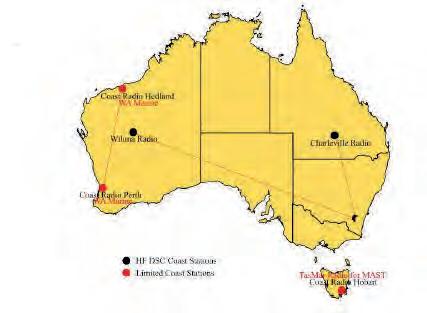
It is the recommended textbook for candidates undertaking examination for the Long Range Operator Certificate of Proficiency (LROCP) and the Short Range Operator Certificate of Proficiency (SROCP).
Procedures and requirements outlined in the handbook are based on the International Radio Regulations formulated by the International Telecommunication Union (ITU), on provisions governing the use of radio transmitters in Australia laid down in the Radiocommunications Act 1992, and on radiocommunications station licence conditions set by the Australian Communications and Media Authority (ACMA).
Careful observance of the procedures covered by this handbook is essential for the efficient exchange of communications in the marine radiocommunications service, particularly when the safety of life at sea is concerned. Special attention should be given to those sections dealing with distress, urgency and safety.
It should be noted that no provision of this handbook, the International Radio Regulations, or the Radiocommunications Act 1992, prevents the use by a vessel in distress of any means at its disposal to attract attention, make known its position and obtain help.
Similarly, no provision of this handbook, the International Radio Regulations, or the Radiocommunications Act 1992, prevents the use by vessels engaged in search and rescue operations of any means at their disposal to assist a vessel in distress.
This edition of the Marine Radio Operators Handbook reflects the new arrangements for Maritime Communication Stations from 1 July 2002. These arrangements include substantial changes to the frequencies monitored by these stations for distress and safety. This edition also includes information regarding MASTREP, which replaces AUSREP as the ship reporting system in Australian waters.
It also reflects the revised transmitting frequencies agreed at the World Radio Communication Conference (2015).
It also contains information about the Global Maritime Distress and Safety System (GMDSS) marine communications techniques which are available for use by small vessels in Australia. The system uses advanced technology and automation to ensure that search and rescue authorities, as well as ships in the vicinity of an emergency, are alerted reliably and rapidly. Both satellite and terrestrial communications form essential components of the GMDSS.
Information about obtaining the Marine Satellite Communications endorsement qualification (MSCe or Satcom) for operators with Inmarsat satellite communications (compulsorily or voluntarily fitted) is available on the web at www.amc.edu.au/handbooks.
The Australian Maritime College acknowledges the contribution of the ACMA, Australian Maritime Safety Authority (AMSA) and the McMurdo Group (chart image page 61).
n 1 S HIP S TATION O P e RATORS
1.O P e RATORS ’ Q UALIFICATIONS
1.1 Australia is a member of the International Telecommunication Union (ITU). This body regulates radio frequency usage, and the operations and use of radiocommunications equipment on a world-wide basis.
1.2 Operators of ship stations, other than those operating exclusively in the 27 MHz marine band, must possess a certificate of proficiency issued in accordance with ITU regulations and the Australian Radiocommunications Act 1992, or a certificate considered to be of an equivalent or higher standard.
1.3 Operators on vessels that are subject to State or Territory legislation should ensure that they are qualified under that legislation.
1.4 Provided the ship radio station is under the control of a person holding a relevant certificate, persons other than the holder of the certificate may operate the equipment.
1.5 Operators of ship radio stations using equipment operating exclusively in the 27 MHz marine band are exempt from operator qualification requirements. However, in the interests of safety, ACMA strongly recommends that these operators qualify themselves with at least the Short Range Operator Certificate of Proficiency.
1.6 Operators of Limited Coast Stations using VHF and/or MF/HF marine bands are required to hold a certificate of proficiency. The minimum qualification is relevant to the equipment fitted at the station and is shown in the table on the following page
1.7 Holders of the Restricted Radiotelephone Operators Certificate of Proficiency (RROCP), and the earlier 3rd Class Commercial Operators
Certificate of Proficiency will continue to be legally qualified even though their radiocommunications equipment may incorporate digital selective calling facilities. However, such persons will need to additionally qualify for the Marine Satellite Communications endorsement if operating Inmarsat C equipment.
1.8 Operators on vessels which are compulsorily equipped with radio equipment under the provisions of the Commonwealth Navigation Act 2012, are required to hold a minimum of the Global Maritime Distress and Safety System General Operators Certificate of Proficiency, issued by the Australian Maritime Safety Authority (AMSA). Further details of this qualification may be obtained from any AMSA office.
Renaming of the Marine Radio Operators Certificates of Proficiency
As of mid-2015 the names of the marine radio operator’s certificates of proficiency changed. The renaming of the MROCP and MROVCP has been changed to reflect ITU terminology and align the naming of Australian certificates with the common world practice.
Marine radio certificates are now issued under the following new names:
1.Short Range Operator Certificate of Proficiency – SROCP (replaces MROVCP)
2.Long Range Operator Certificate of Proficiency – LROCP (replaces MROCP)
The new terminology more clearly reflects the nature and limitations of these internationally recognised certificates and their equivalency with overseas certificates.
The minimum requirements for operators on vessels other than those subject to the Commonwealth navigation Act 2012 are:
Operator Certificates
Long Range Operator Certificate of Proficiency (current)
Marine Radio Operators Certificate of Proficiency
Restricted Radiotelephony Operators Certificate of Proficiency
3rd Class Commercial Operators Certificate of Proficiency
Short Range Operator Certificate of Proficiency (current)
Marine Radio Operators VHF Certificate of Proficiency MROVCP
*A person must be the holder of one of the above marine radiotelephony qualifications to obtain a marine satellite endorsement.
Marine Satellite Communications Certificate of Endorsement
Equipment Carried on Vessel
VHF Marine Radiotelephony Equipment (with or without digital selective calling facilities)
MF/HF Marine Radiotelephony Equipment (with or without digital selective calling facilities)
Inmarsat C or Fleet 77 Equipment
MSCE
Marine Radio Qualifications Required to Operate Marine Radio and Marine Satellite Equipment (excluding GMDSS which is a higher qualification)
or or or
2.EXAMINATION FOR THE LONG RANGE OPERATOR CERTIFICATE OF PROFICIENCY, THE SHORT RANGE OPERATOR CERTIFICATE OF PROFICIENCY AND THe MARINe
2.1 Currently, examination and certification services for the two certificates and the satellite endorsement are provided through the Office of Maritime Communications (OMC) at the Australian Maritime College on behalf of the Australian Communications and Media Authority. In this handbook, the Office of Maritime Communications will be referred to as the OMC, the Australian Maritime College the AMC, and the Australian Communications and Media Authority as the ACMA.
2.2 Syllabi for the two certificates are shown in Appendix 1 of this handbook. Examination questions will primarily be based on symbolised sections as follows:
a)Short Range Operator Certificate of Proficiency (SROCP)
b)Long Range Operator Certificate of Proficiency (LROCP)
For the satellite endorsement syllabus refer to the Maritime Communications Satellite Systems and Equipment Handbook available for printing at: http://www.amc.edu.au/industry/omc/handbooks-and-revision-questions .
2.3 An examination will normally consist of a written exercise.
2.4 At the discretion of the OMC, candidates may undertake an oral rather than a written test.
2.5 Persons wishing to upgrade their qualification must contest the entire examination relevant to the desired certificate. ‘Conversion’ examinations are not available.
3.CANDIDATe eLIGIBILITY AND RePLACeMeNT OF OPeRATORS
3.1 Current legislation does not permit the issue of a certificate of proficiency to a candidate under the age of sixteen. Candidates must be sixteen years of age before being accepted for examination.
3.2 Certificates of proficiency and endorsements will be issued to successful candidates.
3.3 All candidates are required to produce proof of identity and age at the time of examination.
3.4 If an operator’s certificate or endorsement is lost, mutilated or destroyed, or a change of name has occurred, the holder may obtain a replacement by submitting a Replacement Application form (refer www.amc.edu.au/industry/omc/certificates).
3.5 where issue of a replacement certificate or endorsement is required because of damage or change of name, the original certificate or
endorsement should accompany the application. In the case of change of name, documentary proof of the change should be included: for example, a marriage certificate or deed poll document.
3.6 A fee will be charged for the replacement of a certificate or endorsement.
3.7 It is in the interests of candidates applying for a replacement for a lost certificate or endorsement to provide information regarding the place and approximate date of original issue.
4.APPLICATION FOR exAMINATION
4.1 An application to be examined for a certificate or endorsement can be made to the OMC.
4.2 examinations for the marine radio operator qualifications are conducted by appointment and may be held at any location suitable for examination purposes. Many marine rescue organisations, boating clubs and colleges of technical and further education (TAFe) conduct examinations on behalf of the OMC. In special circumstances examinations may be held at ACMA offices.
4.3 examinations for the Marine Satellite Communications endorsement cannot be conducted at an ACMA office and are only available at organisations with suitable Inmarsat equipment available for training.
4.4 examination fees are charged.
5.OPeRATOR TRAINING
5.1 Many marine rescue organisations, boating and fishing clubs, maritime colleges and some colleges of technical and further education (TAFe) provide training courses leading to the marine radio operator qualifications
5.2 Some maritime and TAFe colleges provide training courses leading to the Marine Satellite Communications endorsement.
5.3 The ACMA or the OMC may be able to provide information about local training organisations.
5.4 Persons using this handbook as a study guide should note that much of its content is non-examinable. Careful reference should be made to the detailed examination syllabi shown in Appendix 1
S ECTIO n 2 U S e OF S HIP R ADIO S TATIONS
6. S HIP S TATION L IC e NC e S
6.1 Under the Radiocommunications Act 1992, the operation of marine radio equipment aboard any Australian vessel must be authorised by a licence.
6.2 In the case of shipboard radio equipment operating in the 27 MHz and VHF marine bands, this authorisation is provided to any person by means of a Maritime Ship Station Class Licence. The Class Licence does not have to be applied for and is free of charge. The Maritime Ship Station Class Licence also authorises the operation of ship’s radar equipment and on-board UHF marine communications equipment.
6.3 Frequencies authorised for use, technical and general requirements for the operation of 27 MHz, VHF, radar and UHF on-board marine equipment are shown in the Radiocommunications (Maritime Ship Station - 27 MHz and VHF) Class Licence 2001. Operators of this equipment are legally obliged to observe the conditions set out in this document. Copies of the Class Licence may be obtained from the ACMA’s Internet site (http://www.acma.gov.au) or from any ACMA office.
6.4 The operation of shipboard Inmarsat satellite radio terminals is authorised by another Class Licence. The Class Licence is free of charge and does not need to be issued individually.
6.5 Technical and general requirements for the operation of shipboard Inmarsat terminals are shown in the Radiocommunications (Communications with Space Object) Class Licence 1998. Operators of this equipment are legally obliged to observe the conditions set out in this document. Copies of the Class Licence may be obtained from ACMA’s Internet site (http://www.acma.gov.au) or from any ACMA regional office.
6.6 The operation of shipboard radio equipment operating in MF/HF marine bands is not authorised by a Class Licence. Individual apparatus licences, which attract a fee, are required.
6.7 Application for a MF/HF Ship Station (Class B) Licence may be made in person at any ACMA regional office. Alternatively, a completed application form together with the licence fee may be submitted by mail or through the ACMA’s on-line licensing service.
6.8 A MF/HF marine licence shows the station licensee, and the name and the call sign of the vessel. Frequencies authorised for use, technical and general requirements are detailed in the ACMA’s Radiocommunications Licence Conditions (Maritime Ship Licence) Determination. The station licensee is legally obliged to observe licence conditions set out in this document. Copies of the Determination may be obtained from the ACMA’s Internet site (http://www.acma.gov.au).
6.9 By mutual agreement, a MF/HF Ship Station (Class B) Licence may be transferred from one person or organisation to another person or organisation. However, restrictions may apply where the original licence holder is exempt from licence fees or pays a concessional licence fee. Further information and applications for transfer are available at http://www.acma.gov.au. A fee for licence transfer applies.
6.10 A MF/HF Ship Station (Class B) Licensee should contact the ACMA if:
a) a new vessel with radiocommunications equipment is purchased, or
b)there is a change of the licensee’s address.
6.11 Operators of shipboard radio equipment operating in the VHF and MF/HF marine bands, and operators of most Inmarsat satellite radio terminals, are required to hold appropriate personal qualifications. Details of the minimum qualification requirements are shown in paragraph 1
6.12 Neither class licences nor a MF/HF ship station (class B) licence authorises the operation of a ‘home base’. except in special cases, marine radio equipment in private residences will not be authorised by the ACMA.
7. L IC e NSING OF O TH e R S HIPBOARD R ADIOCOMMUNICATIONS eQUIPM e NT
7.1 The Radiocommunications Act 1992 requires that the possession and operation of all radio transmitters be authorised by a licence. Licences are not required for the operation of satellite navigation receivers (GPS).
7.2 Amateur band transmitting equipment installed on a vessel must be licensed separately. Licences for amateur band equipment will not be issued to any person who does not hold an appropriate amateur operator’s certificate of proficiency.
7.3 emergency Position Indicating Radio Beacons (ePIRBs), mobile phones and Citizens Band (CB) transceivers aboard vessels are authorised by Class Licences issued under the Radiocommunications Act 1992, and do not require individual licensing.
8. A UTHORITY OF TH e M AST e R
8.1 A ship radio station and the service it provides is placed under the authority of the master, skipper, or the person responsible for the safety of the vessel.
9. I NSP e CTION OF S HIP S TATIONS
9.1 ACMA officers may ask that a ship radio station be made available for inspection to ascertain that licence conditions are being met.
9.2 Station licensees of vessels travelling overseas should be aware that the competent authorities in any country where the vessel may visit may ask to inspect the ship station licence and the radio qualification of the operator. Failure to produce these documents may result in an inspection by these authorities to satisfy themselves that the radio station conforms to the requirements of the International Radio Regulations. Station licensees of vessels proceeding overseas carrying 27 MHz, VHF and Inmarsat marine radio equipment should carry copies of the relevant class licences.
10. Se CR e CY OF C OMMUNICATIONS
10.1 Under the International Radio Regulations, an operator and any other person who becomes acquainted with the contents of a radiotelegram, radiotelephone call or radiotelex call is placed under an obligation to preserve the secrecy of such information.
10.2 Secrecy restrictions do not apply to distress, urgency or safety alerts or messages, or any message that is addressed to ‘all stations’.
11. D ISTR e SS C ALLS
11.1 The obligation to accept distress alerts, calls and messages is absolute and such messages must be accepted with priority over all other radiocommunications.
12. FALS e OR De C e PTIV e D ISTR e SS , U RG e NCY OR S AF e TY S IGNALS
12.1 The transmission of false or deceptive distress, urgency or safety signals is strictly forbidden. extremely severe penalties, including imprisonment, exist under the Radiocommunications Act 1992 for any person found guilty of making such a transmission.
13. U NN e C e SSARY T RANSMISSIONS
13.1 Transmissions should be as brief as possible consistent with the legitimate requirement for which a station is licensed. Non essential remarks, bad language and unnecessary conversations should be avoided.
13.2 It is an offence under the Radiocommunications Act 1992 to use a transmitter in a manner that is likely to cause a reasonable person to be seriously alarmed or affronted, or for the purpose of harassing a person.
14. AVOIDANC e OF I NT e RF e R e NC e
14.1 Operators should take every precaution to ensure that their transmissions will not cause harmful interference to other stations. It is important that all operators:
-listen before transmitting, to ensure the frequency is not already in use;
-use the minimum transmitting power necessary for reliable communications; -strictly observe the purpose for which a frequency is assigned; and -keep test signals to a minimum.
15. D OCUM e NTS TO B e He LD O N B OARD
15.1 In addition to the station licence (for a MF/HF system) and operator’s certificate, a copy of this handbook and material suitable for use as a radio log book should be held aboard a vessel.
15.2 It is also recommended that information about the operating hours of, and frequencies monitored by, Limited Coast Stations in the areas the vessel is travelling through should be available aboard to facilitate radio communications. This information should be available from the relevant State or Territory authority or volunteer marine rescue organisation.
16. L OG Kee PING
16.1 Operators should keep a record of all distress alerts and messages transmitted or received. Particulars should include the station or stations with which the messages were exchanged, the frequencies used, and the date and times of transmission and reception.
16.2 Log keeping requirements for vessels compulsorily fitted with radio equipment under Commonwealth or State legislation may be found in the relevant regulations.
16.3 A suggested format for a radio log book page is shown in Appendix 2
17. S HIP S TATION C ALL S IGNS AND I D e NTITI e S
17.1 A MF/HF ship station (class B) licence issued by the ACMA will show the official international call sign allocated to the vessel.
17.2 each call sign is unique and is formed in one of two ways: -three letters, followed by four numbers; or -four letters.
17.3 In conformity with Australia’s international call sign allocation, the first two letters will always be Ax, VZ, VH, or in the series VJ to VN.
17.4 Four letter call signs are allocated only to vessels subject to compulsory radio installation under the Navigation Act 2012 (generally commercial vessels making interstate and overseas voyages).
17.5 On request, a Maritime Mobile Service Identity (MMSI) will be issued by the Australian Maritime Safety Authority (AMSA) to a ship station licensee with an installation capable of digital selective calling techniques. See the AMSA website for more information. (https://www.amsa.gov.au/forms/australian-maritime-mobile-service-identity-application).
17.6 Transmissions from radio equipment aboard survival craft should be identified by the use of the parent vessel’s call sign followed by two numbers (not 0 or 1). The numbers ‘22’ are normally used.
17.7 Stations operating exclusively on VHF marine bands now operate under a Class Licence and a radio call sign is not required (see paragraph 6.3) Operators should use the name of the vessel or other suitable means of identification. Vessels which were licensed prior to 1 July 2001 may continue to use the call sign issued by the then ACA or its predecessor, provided that licensee contact and vessel details remain unchanged.
18. S HIP S TATION I D e NTIFICATION
18.1 Transmissions without identification are forbidden.
18.2 A MF/HF ship station must be identified either by the use of the official international call sign allocated by ACMA or by the ship’s name or, preferably, by a combination of both. If using digital selective calling, the vessel’s MMSI will automatically be inserted into the transmission.
18.3 Ship stations operating exclusively on 27 MHz and/or VHF marine bands may use the vessel’s name or other suitable identification. Vessels which were licensed prior to 1 July 2001 may continue to use the call sign issued by ACMA while the ownership of the vessel, licensee contact and vessel details remain unchanged.
18.4 If transmitting radiotelephony distress, urgency or safety messages, or if involved in search and rescue operations, the utmost care must be taken to avoid confusion between vessels of the same or similar names.
18.5 If transmitting radiotelephony distress, urgency or safety messages, or if involved in search and rescue operations, the use of an official call sign is necessary to avoid confusion between vessels of the same or similar names. If no call sign is available then the full name or registered number followed by the port at which the name or registration is recorded can assist in positively identifying the vessel. If the vessel is not registered then other identification such as the trailer or parked vehicle registration number followed by the ramp location where the vehicle is parked can help to identify the owner in an emergency.
S ECTIO n 3 M ONITORING OF R ADIOT e L e PHONY
R e QU e NCI e S ( wATCHK ee PING )
19. M ONITORING OF R ADIOT e L e PHONY D ISTR e SS AND C ALLING
19.1 Ship stations are encouraged to keep maximum practicable watch on the radiotelephony distress and calling frequencies appropriate to their location and the type of marine radiocommunications equipment fitted.
19.2 watchkeeping requirements for vessels compulsorily fitted with radio equipment under State legislation may be found in the relevant regulations.
19.3 Aural watchkeeping has been replaced by digital selective calling watchkeeping by maritime communication stations.
20. R ADIOT e L e PHONY S IL e NC e Pe RIODS
20.1 The international regulations no longer require silence periods to be observed on the distress and calling frequencies. Those vessels that come under the Safety of Life at Sea regulations maintain a continuous watch on VHF DSC and a listening watch on Channel 16.
20.2 It is still recommended that vessels operating on the MF/HF frequencies observe silence periods, so that operators experiencing communications difficulties on these frequencies can be heard. Operators wishing to observe silence periods should be aware that they start on the hour and half-hour and last for three minutes.
20.3 An accurate clock is also useful to record the time at which communication occurred, particularly in emergency situations.
20.4 Silence periods are not observed on the MF/HF DSC frequencies or the VHF DSC channel.
S ECTIO n 4 F R e QU e NCI e S - Ge N e RAL I NFORMATION
21. U S e OF F R e QU e NCI e S
21.1 A ship station may use only the frequencies that are authorised for its particular activity (for example, pleasure, professional fishing, etc.). These frequencies are detailed in ACMA’s Radiocommunications Licence Conditions (Maritime Ship Licence) Determination No.1 of 1997 and the Radiocommunications (Maritime Ship Station - 27 MHz and VHF) Class Licence 2001. (See Appendix 3 ) except in the case of distress, the use of any other frequency is not permitted. Offenders may be subject to penalties under the provisions of the Radiocommunications Act 1992.
21.2 It is important that frequencies are used only for the purpose for which they are assigned; for example, a frequency shown for communicating with Maritime Communication Stations or Limited Coast Stations must not be used for communicating with other vessels.
22. C ONTROL OF C OMMUNICATIONS
22.1 During routine communications between a ship station and a maritime communication or limited coast station, the Maritime Communication
22.2 Ship stations must not interfere with Maritime Communication Station or Limited Coast Station communications.
22.3 During routine communications between ship stations, the called ship station controls the subsequent exchange of communications.
23. Te ST T RANSMISSIONS
23.1 when it is necessary for a ship station to transmit signals for testing or making technical adjustments that are likely to interfere with the working of a nearby Maritime Communication Station or Limited Coast Station, the prior consent of that station should be obtained.
23.2 All testing signals should be kept to a minimum, particularly on frequencies used for distress, urgency and safety purposes.
23.3 The requirement to minimise testing does not prevent a ship station from making a brief transmission to a local Limited Coast Station to confirm correct equipment operation before the vessel puts to sea.
24. R ADIOT e L e PHONY C ALLING AND wORKING F R e QU e NCI e S
Station or Limited Coast Station controls the working. In order that communications may be exchanged efficiently, all instructions given by Maritime Communication Station and Limited Coast Stations should be obeyed without delay. However, this does not prevent a ship station making a suggestion concerning a working frequency or other on-air operations. calling or working: stations; and
as either -calling frequencies are used to establish communications with Maritime Communication Stations, Limited Coast Stations and other ship - working frequencies are used to exchange messages relating to the operation and movement of vessels and to conduct public correspondence communications.
24.2 All stations may establish communications with the desired station by using a radiotelephony calling frequency. Once communications have been established, communications should be transferred to a working frequency and the messages exchanged. At the conclusion of working, stations should resume monitoring the appropriate calling frequency.
24.3 The majority of radiotelephony calling frequencies are also assigned for distress, urgency and safety calling purposes. This enables ship stations to monitor a single frequency for routine calling from other stations and for safety of life at sea purposes.
24.4 Limited Coast Stations may monitor several of these dual-purpose frequencies. Maritime Communication Stations only monitor HF digital selective calling frequencies.
24.5 It is essential that calling frequencies are not used for the exchange of routine messages.
25. R ADIOT e L e PHONY C ALLING F R e QU e NCI e S
25.1 The main radiotelephony frequencies for establishing routine communications with an Australian Limited Coast Station or another ship are: -2182, 12 359 and 16 537 kHz in the MF/HF marine bands; -Channels 16 and 67 in the VHF marine band
24.1 Radiotelephony frequencies assigned to ship stations, Maritime Communication Stations and Limited Coast Stations are categorised
25.2 Ship stations wishing to attract the attention of Australian Maritime Communication Stations must use digital selective calling (DSC) equipment and dedicated HF DSC frequencies for distress, urgency and safety alerting: 4207.5, 6312, 8414.5, 12 577, and 16 804.5 kHz.
25.3 Certain other radiotelephony frequencies are monitored by some Limited Coast Stations and may be used for establishing communications. Details of these frequencies are shown in Appendix 3.
25.4 In Australia, all radiotelephony distress and calling frequencies or channels are used in the SIMPLEX mode with transmission and reception taking place on the same frequency, enabling all stations to monitor a single frequency (See paragraph 36.1.)
25.5 VHF channel 70 may be used for establishing routine communications using digital selective calling techniques. Further information may be found in paragraphs 86.1 - 86.4
26. R ADIOT e L e PHONY wORKING F R e QU e NCI e S
26.1 Details of radiotelephony frequencies to be used for working with Australian Maritime Communication Stations are shown in Appendix 3
26.2 Details of radiotelephony frequencies to be used for working with Limited Coast Stations and other vessels are shown in Appendix 3
26.3 The frequencies used by the Bureau of Meteorology for transmission of weather forecasts and warnings should no longer be used as working frequencies, even when weather broadcasts are not being made. The weather broadcasts are now on an automatic schedule. There will not be any announcement (on a calling frequency) that the broadcast will start. There is no provision for the Bureau of Meteorology to monitor the frequency prior to the commencement of the broadcast.
26.4 Many of the frequencies designated for working with Maritime Communication Stations are allocated in pairs, with transmission and reception taking place on different frequencies; i.e. DUPLEX (See paragraph 36.2).
26.5 All ship to shore and shore to ship working frequencies in the HF and VHF marine bands are allocated an international channel number. In the interests of brevity and accuracy, ship station operators are encouraged to refer to channel numbers rather than frequencies. Details of channel numbers may be found in the ITU radio regulations.
27. P HON e TIC A LPHAB e T AND F IGUR e C OD e
27.1 In cases of doubtful reception or difficult conditions when passing any radiotelephony message, ship station operators should spell out words and figures using the International Phonetic Alphabet and figure code. Details may be found in Appendix 5
27.2 Use of the phonetic alphabet is particularly important when handling radiotelephony messages concerning the safety of life at sea.
INFORMATION
FOR MARITIME COMMUNICATION STATIONS, COAST RADIO STATIONS AND LIMITED COAST STATIONS
28.1 Ship station operators are encouraged to provide departure, positional and arrival information to a Maritime Communication Station, Coast Radio Station or Limited Coast Station operated by a marine rescue organisation.
28.2 If undertaking a lengthy voyage, a position report should be passed daily to a Maritime Communication Station, Coast Radio Station or Limited Coast Station operated by a marine rescue organisation.
28.3 This information may provide valuable assistance to search and rescue authorities should an emergency situation occur.
29. Re STRICTIONS TO TH e U S e OF R ADIO eQUIPM e NT ON S HIPS
29.1 Ship station licences authorise the use of radio equipment aboard vessels at sea or on inland waters only.
29.2 However, if a vessel is anchored or moored, the use of the ship’s radio station to communicate with the nearest Maritime Communication Station, Coast Radio Station or Limited Coast Station is permitted, providing the lowest practicable transmitting power is used.
29.3 Due to the risk of explosion, radio transmissions must not be made when a vessel is loading fuel, or when loading or discharging any flammable cargo.
29.4 Some overseas communications authorities forbid the use of marine communications equipment whilst in port limits.
C HAPTER 1 Ge N e RAL – Re VISION Q U e STIONS
S e CTION 2: U S e OF S HIP R ADIO S TATIONS
6.12 Is a radio licence required for a 'home base'?
8.1 Under whose authority is the radio station placed under?
10.1 Does secrecy or confidentiality apply to general or public correspondence?
10.2 Does secrecy or confidentiality apply to distress, urgency or safety broadcasts?
11.1 what priority is given to distress calls?
12.1 what is acceptable with regards to false or deceptive distress, urgency or safety calls?
13.1 what is considered as unacceptable with regards to radio transmissions?
13.2 Is using a radio in a threatening or abusive manner acceptable?
14.1 Before transmitting how should you avoid interference to ongoing transmissions?
15. 1 In addition to the station licence, what other materials are advised to be carried?
16.1 what information must be entered into the radio log book?
17.1 Describe a radio call sign
17.7 Is a radio call sign issued under a VHF class licence?
18.1 Complete the following: ‘Transmission without identification is……….’
18.5 During distress communications how should operators identify their transmission?
18.5 without a radio call sign how may a vessel be identified?
19.1 what frequencies or channels are required to be monitored during a voyage?
S
CTION 4: F R e QU e NCI e S – Ge N e RAL I NFORMATION
21.1 what frequencies or channels are authorised for the ship station operator to use?
22.1 what type of station controls communications between a coast station and a ship station?
22.2 what do you understand with regards to ‘avoidance of interference’ on communications from coast stations?
22.3 During ship to ship calls, which station controls communications?
23.1 Prior to making a test transmission, what information should be requested from the station about to be called?
23.2 Test transmissions on distress and
safety frequencies should be kept to what length?
24.1 what is the purpose of a calling frequency? what is the purpose of a working frequency?
24.2 On completion of the exchange of traffic, what frequency should be monitored?
24.3 How are vessels able to monitor a single frequency for distress and calling purposes?
24.4 what frequencies are monitored by Maritime Communication Stations?
24.5 Are calling frequencies eligible for the exchange of routine messages?
25.1 List the main radiotelephony frequencies and channels for routine calling communications
25.2 How are vessels able to contact Australian Maritime Communication Stations?
25.3 what frequencies are available for calling Limited Coast Stations?
25.4 On distress frequencies, what mode of transmission must be used?
25.5 what VHF Channel is reserved exclusively for DSC alerting?
26.4 what is the DUPLex mode of transmission? when would the DUPLex mode be selected?
26.5 In the interest of brevity and accuracy, how would you refer to an HF frequency for making a telephone call?
A station operating on HF channel 802 would be operating in what MHz band?
27.1 whilst experiencing communications difficulties, how would you exchange words?
28.1 what information is requested to be passed on to Limited Coast Stations, such as those operated by rescue organisations?
28.2 During a lengthy voyage, how often are position reports requested?
29.1 Does a ship station licence authorise the use of radio equipment in port?
29.2 Your vessel is in port limits, anchored, but the public network facilities are unavailable what steps may you take in order to communicate to shore?
29.3 Are normal radiocommunications safe whilst loading fuel?
29.4 Are radio transmissions permitted when the vessel is within port limits?
CHAPT e R 2
RADIO PROPAGATION
S ECTIO n 5 F R e QU e NCY C HARACT e RISTICS
Frequency Bands (See Appendix 3 table 15)
Amplitude
Time Period
One cycle of a sinusoidal waveform is shown. This occurs in one Time Period, measured in seconds.
The frequency of the waveform is measured in the number of cycles which occur in one second, known as a Hertz.
There are 1000 Hertz to the kHz, (kiloHertz)
There are 1,000,000 Hertz to the MHz (MegaHertz)
There are 1,000,000,000 Hertz to the GHz (GigaHertz)
The radio spectrum has been divided into frequency bands. Marine radio equipment operates mostly in the Medium Frequency (MF), High Frequency (HF) and Very High Frequency (VHF) bands.
Medium Frequency 300 – 3000 kHz (or 3 MHz)
High Frequency 3 – 30 MHz and Very High Frequency 30 – 300 MHz.
30.1 Lying between 80 and 350 km above the earth’s surface are a series of gaseous layers known as the Ionosphere. These gaseous layers become energised or ionised by the sun’s rays, e.g. ultra-violet or x-rays.
30.2 There are many variables that affect this radiation, including the time of day, the seasons and solar flares or sunspots.
30.3 There are three ionised layers in the ionosphere. These layers are designated by the letters D, e and F. During the daytime, the ionosphere consists of the D, e, and F layers (the F layer being subdivided into the F1 and F2 layers). At night the important layers are the e and F (or F2) layers, as the D layer becomes de-ionised and less effective.
31. R ADIO P ROPAGATION
31.1 electromagnetic energy emanating from a radio transmitter antenna radiates in an omnidirectional manner. The radiated energy consists of sky waves, which travel upwards, and ground waves, which travel along the surface of the earth and follow its curvature to some extent. Ground waves will generally travel further over the sea than over the land.
31.2 The useful communication range of the ground wave component depends upon the frequency of the transmission. The higher the frequency
used, the shorter will be the range of the ground wave.
31.3 The sky wave component travels up at many different angles and, depending on the frequency of the transmission, may be reflected back to earth by the ionosphere.
32. R ADIO P ROPAGATION AT MF (300 – 3000 KHz)
32.1 During the daytime, at medium frequencies, the sky wave component is not reflected back to earth by the ionosphere. Marine radio communication equipment therefore makes use of the ground wave for communications purposes. Typical ranges are from 100 to 400 nautical miles.
32.2 At night-time, the sky wave component of the wave is reflected back to earth at a far greater distance than that covered by the ground wave, but only the ground wave can be used for reliable communications.
33. R ADIO P ROPAGATION AT HF (3 – 30 MHz)
33.1 During the daytime, at HF, the sky wave component of the transmitted frequency is reflected back to earth. The distance at which the reflected energy is received is determined by the frequency selected. In the HF band of frequencies, marine communications equipment offers the operator a choice of frequencies in the 4, 6, 8, 12 and 16 MHz bands.
33.2 At night-time, the HF sky wave is still reflected back to earth but at a greater distance than during the day time. A lower frequency would be required to cover the same range that a higher frequency was required for during the daytime.
33.3 Generally speaking, the greater the range or distance required for communications, the higher the frequency that must be used. Long-range communication is therefore possible using the higher frequencies in the HF band.
33.4 MF/HF marine radio equipment offers the operator the choice of frequencies in the various bands. This allows the operator to select a frequency which will be suitable for the distance over which communication is required at any time of day or season.
33.5 Less long range interference will be experienced on the lower frequencies. In tropical waters, high static levels may make communications difficult or impossible at times. The correct selection of frequency is the lowest frequency that will provide satisfactory communications with the desired station. However, this is often a matter of experience rather than textbook knowledge.
34. RADIO PROPAGATION AT VHF (30 – 300 MHz)
34.1 During the daytime or night-time, any sky wave radio energy transmitted at VHF is not reflected back to earth. Marine communications equipment makes use of the ground wave component at VHF. Under normal conditions, the range at VHF is said to be slightly greater than the visual line of sight, and is determined by the combined height of the transmitting and receiving antennas over an all water path. Range at VHF is therefore said to be only effective for short distances.
During certain atmospheric conditions, particularly during the summer months, the ground wave may be refracted round the earth’s surface for a far greater range than would normally be expected at VHF. This phenomenon is known as ‘ducting’ and should not be regarded as normal.
34.2 Radio energy at VHF, condensed into a beam, may be used to communicate from the earth’s surface to an orbiting satellite.
35. M OD e S OF C OMMUNICATIONS
35.1 Radiotelephony is the most common mode of transmission for mariners. There are two main types: Amplitude Modulation (AM) and Frequency Modulation (FM). In both these systems the voice signal (audio) is combined with the radio frequency that is required for the transmission to produce the modulated signal. Amplitude modulation produces an upper and a lower sideband either side of a carrier frequency signal which contain identical audio information. This system, sometimes referred to as ‘Double Sideband AM’, is the form of modulation used by commercial broadcasting stations.
35.2 The Single Sideband Mode of Transmission and Reception:
Single Sideband (SSB) is mandatory on all MF/HF marine frequencies. Marine communications equipment uses the upper sideband (USB). The single sideband mode of communication has two variants: AM compatible and SSB.
35.3 AM Compatible (H3E):
The first of these two sideband modes consists of the USB plus a full strength carrier signal. This is known as the AM compatible mode, often referred to as simply AM. International regulations only require the use of AM (H3e) on 2182 kHz for distress, urgency or safety communications H3e is known as the emission designator for this mode of transmission. Marine communications equipment with a dedicated 2182 kHz button will usually revert to the AM mode when selected.
35.4 SSB (J3E):
The second of these two sideband modes is known as SSB (J3e), where J3e is the emission designator for this mode of transmission. This mode is defined as radiotelephony using amplitude modulation single sideband with suppressed carrier. It is often referred to as SSB and is used on all MF/HF marine frequencies. The transceiver operating in the SSB mode will receive both SSB and AM signals. However, the AM signal will have a background tone. The transceiver operating in the AM mode will receive the SSB signal badly garbled and unintelligible.
35.5 Digital Selective Calling (DSC):
The Digital Selective Calling (DSC) mode is used on frequencies in the MF, HF and VHF bands. On the medium or high frequencies, the transmission consists of a brief burst of data, typically five to seven seconds duration, by the Narrow Band Direct Printing (NBDP) or telex mode. F1B is the emission designator for this mode of transmission. At VHF, the transmission is a short burst of data of approximately half a second duration.
36. SIMPL ex AND DUPL ex C OMMUNICATION M OD e S OF O P e RATION
36.1 SIMPLEX
Simplex operation makes use of a single frequency for both transmission and reception. The operator will press the talk (PTT) button on the microphone in order to transmit. Releasing the button enables the operator to receive incoming signals. This also permits all stations to listen on a common frequency (such as during distress traffic and All Stations calls).
36.2 DUPLEX
Duplex operation is when transmission and reception take place simultaneously on two separate but paired frequencies: for example, for radiotelephone calls taking place on the public network system. Operators usually select an internationally designated channel in the HF band of frequencies for telephone calls. The ship station transceiver is programmed for transmission on frequency A and reception on frequency B. The coast radio station transceiver operating on the same international channel would therefore be programmed to receive frequency A and to transmit on frequency B.
36.3 The different transmit and receive frequencies allow ship stations fitted with the necessary facilities to transmit and receive simultaneously. Because the transmitter and the receiver are both operating at the same time, radiotelephone calls can be conducted in a similar manner to a telephone call made over the land system, with each party being able to speak and hear at the same time. Ship stations cannot communicate with each other using the Duplex mode of operation.
36.4 The duplex filter units allowing simultaneous transmission and reception are usually only found on expensive MF/HF and VHF equipment. The use of widely separated antennas, one for transmission and another for reception, may also be required.
36.5 MF/HF and VHF ship stations without the duplex facility must use the paired frequencies alternately: that is, for transmission or reception, but not at the same time. Use of the word ‘over’ to prevent confusion and ensure efficient use of time on air is explained in paragraph 136 (See SIMPLEX 36.1)
Four Digit VHF Channels
Due to increased need for marine VHF Channels for commercial use, ITU authorised and developed a new channel plan for the following VHF marine radio frequencies:
Channels 19, 20, 78 and 79 which were duplex have now been split into 8 simplex channels numbered 1019, 2019, 1020, 2020, 1078, 2078, 1079 and 2079
This new channel plan took effect on January 1, 2017.
C HAPTER 2 R ADIO P ROPAGATION –Re VISION Q U e STIONS
S e CTION 5: F R e QU e NCY C HARACT e RISTICS
30.1 what are the gaseous layers some 80 to 350 km above the earth’s surface known as?
30.2 what variables affect the ionosphere?
30.3 How many gaseous layers of the ionosphere are there during the daytime?
31.1 Radio waves radiating from a transmitting antenna can be divided into which two basic types of waves?
31.1 In general, what range is covered by the ground wave component of radio energy?
32.1 At MF, is the sky wave component of the radiated energy returned back to earth during daylight hours?
what is the MF frequency band?
(See Table 15, page 96.)
32.2 what is the effect on MF frequency during night-time?
n OTES
33.1 At HF, what determines range of transmission?
what is the HF frequency band? (See Table 15, page 96.)
33.2 what is the effect on the communication range of HF frequencies at night-time?
33.2 In MF/HF, generally speaking what determines range of transmission?
33.2 What frequencies are used for long range communications?
34.1 In VHF, what section of the radiated
energy is made use of?
During certain atmospheric conditions, what phenomenon greatly increases transmission range at VHF?
35.2 what mode of communication is mandatory on marine MF and HF frequencies?
35.3 what transmission emission mode is available for distress communications on 2182 kHz?
35.4 what transmission emission mode is required on all marine MF/HF transmissions?
35.5 what transmission emission mode is used for MF/HF DSC alerts?
36.1 what transmission mode is required for distress broadcasts? Define SIMPLex transmission
36.2 when would the DUPLex mode of transmission be used? Define the DUPLex mode of transmission.
SECTIOn 6 MARITIMe COMMUNICATION STATIONS
Important note - The Bureau of Meteorology now transmits a range of high seas and coastal weather warnings on a combination of previously used working frequencies and a set of new frequencies. These frequencies are listed in Appendix 3. The forecasts and warnings are automatically generated and broadcast. Vessels will not be able to communicate with these stations as they will only operate as broadcast stations.
Aural monitoring of other MF/HF radiotelephony distress and calling frequencies by Limited Coast Stations continues, but the coverage provided by these Limited Coast Stations may not be complete. Some weather information also continues to be available by radiotelephony from these stations.
Contact the relevant State/Territory authority or your local volunteer marine rescue organisation to find out information about Limited Coast Stations in your area.
Note - Unless otherwise specified, the term ‘Limited Coast Stations’ will be used to refer to both the coast radio stations operated by the State/Territory marine authorities, volunteer marine rescue organisation and other Limited Coast Stations.
37. M ARITIM e C OMMUNICATION S TATION Se RVIC e S
37.1 Australian Maritime Communication Stations are operated by Kordia Solutions Ltd. The Kordia Network Control Centre is co-located with the Australian Rescue Co-ordination Centre (RCC) operated by Australian Search and Rescue (AusSAR) in Canberra. Search and Rescue (SAR) and safety of life at sea services are performed by the RCC on behalf of the Australian Maritime Safety Authority (AMSA).
37.2 A Maritime Communication Station is a station on land established for the purpose of communicating with vessels at sea. Australian Maritime Communication Stations provide the following services to vessels: -search and rescue (SAR) operations in conjunction with the Rescue Co-ordination Centre (RCC) in Canberra (RCC Australia); -weather forecasts and warnings for coastal waters and high seas areas from the Bureau of Meteorology, transmitted automatically; -continuous automated watch of HF digital selective calling (DSC) frequencies for distress calls for the purpose of safety of life at sea; and - continuous watch of HF radiotelephone distress frequencies for distress calls.
38. L OCATION OF M ARITIM e C OMMUNICATION S TATIONS
38.1 Under the current contract with Kordia, radiocommunications to vessels at sea are provided by two Maritime Communication Stations - wiluna (wA) and Charleville (Qld). The network is designed to sense the power of a transmission and respond from the appropriate station. The two stations are centrally controlled from the Network Control Centre (NCC) in Canberra.
39.1 Maritime Communication Stations can be contacted via a digital selective calling service, which is identified by a nine digit code known as a Maritime Mobile Service Identity (MMSI). The MMSI for both Australian Maritime Communication Stations is 005030001.
39.2 After establishing contact by digital selective calling, Australian Maritime Communication Stations will switch to a radiotelephone channel and respond with the call sign ‘RCC Australia’.
39.3 Maritime Communication Stations may also respond with the use of their official radiotelephony call sign, ‘RCC Australia, VIC (Victor India Charlie)’.
40. M ONITORING OF F R e QU e NCI e S BY M ARITIM e C OMMUNICATION S TATIONS ( wATCHK ee PING )
40.1 Collectively, the two Maritime Communication Stations provide a continuous watch on the HF digital selective calling frequencies reserved for distress, urgency and safety. See paragraph 83.1
40.2 Maritime Communication Stations do not operate in the 27 MHz marine band. Potential users should check if Limited Coast Stations in their local area are monitoring frequencies in this band before relying on it for communication.
40.3 maritime Communication Stations do not provide aural monitoring of the international radiotelephony distress and calling frequency in the 2 mhz band (2182 khz) or the VhF marine band (VhF channel 16). potential users should read Section 7 for more information and check if Limited Coast Stations in their local area are monitoring these frequencies before relying on them for communication.
40.4 maritime Communication Stations do not provide mF digital selective calling monitoring in the 2 mhz band (2187.5 khz). potential users should check if Limited Coast Stations in their local area are monitoring this frequency before relying on it for communication.
41.1 in urgent medical cases, a digital selective calling (dSC) urgency alert may be used to establish communications with the Maritime Communication Stations.
41.2 australian Maritime Communication Stations have formal arrangements with health authorities and will relay medical advice to and from vessels at sea in an emergency. this service is free of charge.
important note - potential users should seek current advice from the relevant State/territory authority about the operation of these services.
the three hF stations listed in this section are licensed as Limited Coast Stations. these stations may be referred to elsewhere in this handbook as Coast radio Stations.
the VhF only stations operated by (or for) the State and northern territory marine authorities are also licensed as Limited Coast Stations. both types of station as well as other Limited Coast Stations are referred to collectively as Limited Coast Stations.
43.2 These services are provided through Charleville, Wiluna, Coast Radio Hobart, Coast Radio Perth and Coast Radio Port Hedland.
16 and 70 (DSC) services along the Victorian coast (Marine Radio Victoria) using nine Limited Coast Stations.
42.2 Kordia Rescue Coordination Centre station also remotely controls Channel 16 and 67 VHF service in Darwin (Darwin Coast Radio); VHF Channels VHF network. The networks maintain watchkeeping on VHF Channel 16.
42.3 The SA, Qld and NSW Governments also operate extensive VHF networks covering their coast lines. Coast Radio Hobart operates a statewide
RCC AUSTRALIA DSC
Continuous Automated Watch on HF DSC Frequencies:
4207.5 kHz
6312.0 kHz
8414.5 kHz
12577.0 kHz
16804.5 kHz
Automatic broadcasts of weather forecasts and warnings for coastal and high seas areas.
MCSs at Wiluna and Charleville
MMSI: 005030001 (for both stations)
Callsign: RCC Australia, V.I.C. (for both stations)
Intended coverage: coastal and ocean areas extending to the limits of Australia's Search and Rescue Region.
Phone: +61 2 6230 6811
Fax: +61 2 6230 6868
Email: rcc@amsa.gov.au
RCC AUSTRALIA RADIOTELEPHONE
Continuous Radiotelephone Watch on HF Distress and Safety Frequencies:
4125 kHz 6215 kHz 8291 kHz 12290 kHz 16420 kHz
Navigation warnings broadcast on 8176 kHz
43.3 Services provided by these stations include 24 hour listening watches on 4125 kHz, 6215 kHz, 8291 kHz, 12290 kHz and 16420 kHz for distress and safety situations and the broadcast of navigation warnings on 8176 kHz.
43.4 8291 kHz is used for announcing safety traffic prior to transmitting the safety traffic on a working frequency. It is important to restrict radio traffic on these frequencies to distress, urgency and safety calls. the operator must not use 8291 kHz for routine or general calling. Radio checks or calls of a general nature should be directed to volunteer marine rescue groups or other service providers.
43.5 The following duplex and simplex radiotelephone working channels are available for communications with Charlieville and Wiluna after the the initial call: 4366/4074 kHz (ch 404), 6519/6218 kHz (ch 607), 6227 kHz simplex, 8734/8210 kHz (ch 806), 8294 kHz simplex, 13152/12305 kHz (ch 1226), 12359 kHz simplex, 17251/16369 kHz (ch 1604), 16534 kHz simplex
43.6 Coast Radio Hobart Coast Radio Hobart monitors 4125, 6215 and 8291 kHz during the hours of 0700-1900 local time. More details at https://tasmaritime.com.au/
43.7 Coast Radio Perth and Port Hedland Coast Radio Perth and Port Hedland monitor 4125, 6215 and 8291 kHz continuously
43.8 Navigation warnings will be broadcast on 8176 kHz in accordance with a schedule commencing 3 minutes prior to the hour (utC). Navigation warning broadcast schedules can be obtained from the State/Nt marine authorities.
WA Marine
Wiluna Radio
Charleville Radio
Coast Radio Perth
Coast Radio Hedland
Coast Radio Hobart WA Marine
HF DSC Coast Stations
Limited Coast Stations
TasMar Radio for MAST
44.1 VHF radio distress and safety services include 24 hour monitoring of VHF Channel 16 for distress, urgency and safety traffic and regular broadcasts of weather information on VHF Channel 67.
44.2 VHF radio distress and safety services on Channels 16 and 67 are provided in the following coastal areas:
- Queensland - Sea areas adjacent to Fraser Island with continuous coverage through to the Tweed Coast area, along with sea areas adjacent to Townsville;
- New South wales - Sea areas adjacent to Newcastle, with continuous coastal coverage through to the Nowra area;
- Victoria - The Port Phillip Bay / western Port Bay area and adjacent sea areas;
-South Australia - Sea area Ceduna to Discovery Bay and Gulf waters;
- Tasmania - Sea areas surrounding Tasmania and adjacent to Victoria;
- western Australia - Sea areas adjacent to Perth; and
-Northern Territory - Sea areas adjacent to Darwin
The Kordia Rescue Coordination centre station also remote controls:
-a channel 16 and 67 VHF service in Darwin (Coast Radio Darwin);
-VHF channels 16 and 70 (DSC) services along the Victorian coast (Marine Radio Victoria) using nine limited coast stations
44.3 Vessel operators should note that VHF Channel 16 is for distress, urgency, safety and routine calling. It is important to restrict radio traffic on VHF Channel 16 to distress, urgency and safety calls. This does not mean that operators cannot use VHF Channel 16 for routine calls, but where possible working or on demand channels should be used.
44.4 Vessel operators should note that VHF Channel 13 is used for ship to ship maritime safety information (See Appendix 4).
S ECTIO n 8 L IMIT e D C OAST S TATIONS
The service provided by Limited Coast Stations is restricted to communications concerning the safety, movements and operations of vessels in their vicinity. This service may include communications relating to fishing or other commercial operations, club events, the broadcast of weather, navigational information, and Search and Rescue. Use of services other than distress may be limited to members of organisations linked to the Limited Coast Station. 45.2 Limited Coast Stations are not permitted to handle public correspondence to or from destinations ashore. 45.3 Limited Coast Stations may offer a service to vessels in the MF/HF, 27 MHz or VHF marine bands. Details of frequencies assigned to ship radio stations to communicate with Limited Coast Stations are shown in Appendix 3
S TATION
46.1 Limited Coast Stations are stations on land established for the purpose of communicating with vessels at sea. Such stations generally fall into one of the following categories:
-stations serving the professional fishing industry;
-stations established by the operators of small commercial vessels such as charter vessels, tugs, etc;
-stations established by boating and fishing clubs to provide a service for their members;
-stations established by port or harbour management authorities to co-ordinate the movements of vessels within and near a port; or - stations established by recognised marine rescue organisations to supplement the safety of life at sea service offered by Coast Radio Stations and Maritime Communication Stations.
47.HOURS OF OPeRATION FOR LIMITeD COAST STATIONS
47.1 There are no fixed hours for the radio service provided by Limited Coast Stations and many do not offer a continuous service Hours of operation
are determined by local requirements or, in some cases, by State Government legislation.
47.2 In the interests of safety, ship radio station operators are encouraged to familiarise themselves with local Limited Coast Stations, in particular those offering a marine rescue service, regarding hours of operation and frequencies monitored.
48. I D e NTIFICATION OF L IMIT e D C OAST S TATIONS
48.1 Limited Coast Stations operating in the MF and HF marine bands should identify themselves by use of their name and the official call sign allocated to them by ACMA.
48.2 Limited Coast Stations operating in the VHF marine bands may use their official call sign and/or other approved identification such as the organisation’s name. examples: Queensland Tug and Salvage, VKQ 445 Moreton Bay Boat Club, Sandringham Coast Guard, etc.
48.3 Limited Coast Stations offering a digital selective calling service are identified by a nine digit code known as a Maritime Mobile Service Identity (MMSI).
S ECTIO n 9 VHF M ARIN e Re P e AT e RS
49. P RINCIPL e OF O P e RATION
49.1 VHF communications range depends mainly on the height of the antennas of the transmitting and receiving stations. By using VHF marine repeater stations, the range of ship to ship, ship to shore and shore to ship communications can be significantly increased.
49.2 VHF marine repeaters are unmanned shore installations usually located at geographically high points. They are designed to transmit and receive simultaneously and will retransmit or ‘repeat’ all signals received. The retransmitted signals can be received by any station listening on the repeater channel.
49.3 Limited Coast Stations operated by marine rescue organisations routinely monitor VHF repeater channels operating in their area.
49.4 Not all coastal areas of Australia are served by VHF marine repeaters.
50. VHF M ARIN e Re P e AT e R C HANN e LS
50.1 VHF marine repeaters operate in the DUPLex mode on channels 21, 22, 80, 81 or 82.
50.2 For their own safety, boat owners should ensure that they are familiar with the location and operating channel of their local repeater.
50.3 Digital selective calling alerts using VHF are confined to channel 70 and will not operate through repeaters.
51. U S e OF VHF M ARIN e Re P e AT e RS
51.1 In most cases VHF marine repeaters are installed and maintained by marine rescue organisations as a service to mariners and are available for use by all licensed VHF ship stations. However, in order to minimise congestion, if direct ship to ship or ship to shore communications are possible on a non-repeater channel, this must be used in preference.
51.2 Repeater channels must not be used as ‘chatter channels’. Communications must be restricted to those concerning the movements of vessels and safety of vessels and persons. To discourage lengthy conversations, repeaters will incorporate an automatic time restriction of approximately thirty seconds.
51.3 If not apparent by monitoring, a ship station can gain an indication of its ability to access a repeater by momentarily pressing the microphone button. If a brief (approximately one second) burst or ‘tail’ of noise is heard from the loudspeaker when the button is released, then the vessel is activating the repeater. If a 'tail' is not heard, it is probable that the vessel is out of range of the repeater.
51.4 Operators using VHF equipment equipped with an ‘International’ or ‘USA’ channel switch should note that it is essential that the switch be in the ‘International’ position to access repeaters. (See paragraph 73.1)
CHAPTER 3 MARITIMe COMMUNICATION, COAST RADIO AND LIMITeD COAST STATIONS - REVISION QUESTIONS
Se CTION 6: M ARITIM e C OMMUNICATIONS S TATIONS
37.2 What services are provided by Maritime Communications Stations?
38.1 Where are the Australian Maritime Communications Stations located?
39.1 How are Maritime Communications Stations identified?
39.2 How are the Australian Maritime Communications Stations contacted?
39.3 What is the radiotelephony callsign for RCC Australia?
40.1 What watchkeeping services do Australian Maritime Communications Stations provide?
40.3 Do Maritime Communications Stations monitor the MF/HF radiotelephony distress frequencies?
40.3 Do Maritime Communications Stations monitor VHF Ch70?
40.4 Do Maritime Communications Stations monitor MF 2187.5 kHz DSC?
41.2 Do Maritime Communications Stations provide free medical advice?
SECTION 7: STATE ANDNORTHERN TERRITORY HF (COAST RADIO STATIONS) AND VHFSTA
TIONS
42.1 What service is provided by Coast Radio
Stations?
43.1 Within what range or distance from the Australian coast do the Coast Radio Stations provide a distress and safety service?
43.2 What radiotelephony frequencies are monitored by Coast Radio Stations?
43.3 What HF frequency is used for the broadcast of navigational warnings?
43.4 What radiotelephony frequencies
43.2 How many Coast Radio Stations provide a distress and safety communications service around the Australian coast? are supplementary to 2182 and 8291 kHz and may be used for routine calling?
SECTION 8: LIMITED COAST STATIONS
45.1 What services are provided by a Limited Coast Station?
45.2 Can Limited Coast Stations handle public correspondence traffic?
45.3 In what frequency bands do Limited Coast Stations provide facilities?
46.1 What is the purpose of a Limited Coast Station?
46.1 What type of stations could be described as Limited Coast Radio Station?
47.1 Generally speaking, what are the working hours of Limited Coast Stations?
SECTION 9:VHF MARINE REPEATERS
49.1 Name one method by which the range of a shore-based VHF station can be increased.
50.1 List the VHF channels available for marine repeater.
50.3 Would a DSC service be available on a Marine VHF repeater channel?
51.1 Should you use a VHF repeater channel if direct communications are possible using another channel?
44.1 What services are provided by Coast Radio Stations on VHF Ch16?
44.1 What VHF channel is used for the regular broadcast of weather information on VHF?
44.3 VHF Ch 16 is intended for what type of communications?
44.4 What VHF channel is reserved for ship to ship maritime safety communications?
48.1 How are Limited Coast Stations identified?
48.3 How is a Limited Coast Station identified if it offers a Digital Selective Calling Service (DSC)?
51.2 What is the purpose of automatic time restrictions on marine VHF repeaters?
CHAPT e R 4
PO we R SUPPLI e S
S ECTIO n 10 C AR e AND M AINT e NANC e OF B ATT e RI e S
52. L OCATION OF B ATT e RI e S
52.1 The location of a battery supplying marine radio equipment should be chosen to ensure that, as far as practicable, the battery is:
-protected from the elements;
-readily accessible for routine maintenance;
-located reasonably close to the transceiver;
-located as high in the vessel as practicable;
- well ventilated to dissipate the hydrogen gas produced (if located within a wheelhouse or other compartment, venting to the outside may be necessary);
-not located with other items of equipment that could, in heavy weather, fall across the battery and cause short-circuiting; and -not located in the same compartment as a different type of battery, for example, alkaline cells.
53. C ONSTRUCTION OF Le AD A CID Ce LLS
53.1 Lead acid cells have a voltage of 2 volts per cell, regardless of size. Larger size cells will supply higher current than smaller cells, or the same current for longer periods. The ability of a cell to produce current for a period of time is known as the cell’s capacity and is usually measured in ampere-hours (Ah) or, with batteries designed for motor vehicle use, in ‘cold cranking amps’ (CCA).
53.2 A chemical combination of lead and lead peroxide plates and the sulphuric acid in the electrolyte (the liquid solution within the cell), produces a voltage difference between the plates. This voltage difference allows a current to flow through any load, such as a radio, connected across the battery terminals and is called direct-current or ‘dc’.
53.3 when the acid in the electrolyte or the material in the plates is used up, the voltage no longer exists and current cannot flow. At this point, the cell is said to be discharged or ‘flat’.
53.4 This situation is reversible by passing a current in the opposite direction. This process reverses the chemical reactions in the cell and is known as charging.
54 C ONN e CTION OF Le AD A CID Ce LLS
54.1 Cells may be connected in series, that is, the positive terminal of one cell to the negative terminal of another, to produce higher voltages. Three cells connected in series will give a battery of 3 x 2 volts = 6 volts; six cells connected in series will give a battery of 6 x 2 volts = 12 volts.
54.2 Most modern lead-acid batteries are supplied in 6 or 12 volt combinations and may themselves be connected in series to provide the required output voltage; for example, two 12 volt batteries connected in series will produce a voltage of 2 x 12 volts = 24 volts.
54.3 Connection of lead-acid batteries in parallel, that is, positive terminal to positive terminal, negative terminal to negative terminal, will produce the same output voltage as a single battery, but the ability to supply current (capacity) will have been increased. For example, two batteries each supplying 12 volts with a capacity of 60 ampere-hours, when connected in parallel, will provide a voltage output of 12 volts with a capacity of 120 ampere-hours.
55. eSS e NTIAL B ATT e RY M AINT e NANC e
55.1 The functioning of radio equipment is dependent on power supplied by the battery. If it is to provide adequate performance in the event of an emergency, regular and careful maintenance is required.
55.2 A battery’s service life also depends on the manner in which it is treated.
55.3 To ensure the best performance from a battery it is important that a battery: -is kept clean, dry and free from terminal corrosion; -has the electrolyte kept at the correct level; and -is kept correctly charged.
56. B ATT e RY C L e ANLIN e SS
56.1 A battery top should be kept clean. A dirty battery top may hold spilt electrolyte on its surface thereby providing a path for the electrical current to leak away. It is important to keep the outside surfaces of a battery dry and free of contamination.
56.2 Corrosion forming on terminal clamps may seriously affect, or even prevent, the ability of the battery to supply current. Corrosion will be evident by the formation of a white-green powder between the battery terminals and the terminal clamps. In this situation, the terminal clamp should be removed and both it and the terminal post cleaned.
56.3 To minimise the likelihood of corrosion, terminal posts and clamps should be lightly smeared with Vaseline™ or petroleum jelly.
57. eL e CTROLYT e Le V e L
57.1 The level of electrolyte inside a battery is important. As a result of the chemical action inside a battery, water is lost. This should be replaced with distilled or demineralised water.
57.2 Seawater must not be used under any circumstances.
57.3 The level of the electrolyte should be maintained at approximately 10 mm above the plates unless otherwise specified by the manufacturer.
57.4 If the electrolyte level is too high, it may overflow during charging, providing an unwanted discharge path. If the electrolyte is too low, the plates are exposed to the air and permanent damage and loss of capacity may result.
57.5 It may be noticed that a battery that is nearing the end of its useful life will require more frequent topping-up than has been previously necessary.
57.6 Low-maintenance batteries will require infrequent topping-up. Maintenance-free batteries may require none at all.
58. C ORR e CT C HARGING
58.1 To provide the best service, a battery must be correctly charged. Both overcharging and undercharging can seriously affect its performance.
58.2 On small vessels the usual means of charging the radio battery will be an alternator or generator attached to the vessel’s engine. An associated regulator, which reduces the charging current as necessar y, should prevent overcharging.
58.3 Vessels that are used frequently (say, several times each week) should have no problem maintaining a fully charged radio battery. However, on vessels that are used relatively infrequently (once every few weeks), it is likely that during storage even a battery that starts as fully charged will self-discharge and go flat.
58.4 For safety reasons, it is important that the vessel owner is able to determine the general condition of a battery and its ability to supply current over a period of time (its capacity). An indication of the level of charge in a battery may be obtained by either: -measuring the specific gravity of the electrolyte; or -measuring the on-load terminal voltage.
59. Me ASURING TH e S P e CIFIC G RAVITY
59.1 The specific gravity (SG), also called the relative density, of the electrolyte (the liquid inside the battery) varies proportionally with the amount of charge in the battery. It is highest when the battery is fully charged and lowest when the battery is fully discharged or flat. It follows that the amount of charge in a battery can be determined by measuring the specific gravity of the electrolyte.
59.2 A simple, inexpensive device called a hydrometer is used to measure specific gravity.
Electrolyte being measured
Weight to hold float erect
hose
The Hydrometer
59.3 In general, for a fully charged battery, the specific gravity should measure about 1.250. Half charge will be indicated by a reading of 1.200 and fully discharged by 1.150. All cells in a battery should indicate a similar specific gravity. A variation of more than about 0.025 will indicate a faulty cell and the battery should be replaced.
59.4 Specific gravity readings should not be taken immediately after topping-up a cell, as the added water will float towards the top of the cell and give a false reading. Charging for thirty minutes or more after topping-up will mix the electrolyte and allow accurate readings.
59.5 Batteries which have cells where the specific gravity readings fail to rise, or respond poorly to adequate charging, should be replaced.
60. Me ASURING TH e O N -L OAD Te RMINAL V OLTAG e
60.1 Measurement of the terminal voltage when a battery is supplying current to a load, such as a radio, will also provide an indication of the amount of charge in a battery. This measurement is known as the on-load terminal voltage.
60.2 For a 12-volt battery, the on-load terminal voltage should not fall below approximately 11.4 volts while transmitting. If the voltage does fall significantly below this figure, the battery requires charging. If, after charging, the on-load terminal voltage still falls significantly below 11.4 volts, it is an indication of a faulty cell and the battery should be replaced.
60.3 Measuring of the off-load (that is, when the battery is idle) terminal voltage of a battery is a poor indication of its condition.
61. L OSS OF C APACITY
61.1 A battery will suffer a gradual loss of capacity during its life. This is inevitable and the battery should be replaced when the capacity loss becomes significant.
61.2 Many lead-acid batteries have a commercial life of only two to three years.
61.3 However, the useful life of a battery can be considerably shortened by: -operating a battery in a low state of charge for long periods; -allowing a battery to stand in a discharged state for long periods; -leaving a charged battery for long periods without periodic charging; and -overcharging.
62. B ATT e RY H AZARDS
62.1 There are two hazards associated with lead-acid batteries that ship station operators should be aware of: -the risk of explosion; and -the risk of chemical burns.
62.2 As a result of the chemical process occurring within the cells of a battery during charging, hydrogen gas is produced. when mixed with air, this can form a highly explosive mixture which can be ignited by a naked flame, a lighted cigarette, or a spark. The spark caused by breaking or making an electrical connection in the vicinity of the charging battery may be sufficient to ignite the hydrogen-air mixture. Batteries should be located as close to the radio equipment as possible, and placed in a well ventilated container or locker
62.3 If using metal tools to work on battery connections, extreme care must be taken to ensure that terminals are not short-circuited.
62.4 The electrolyte in battery cells contains Sulphuric Acid. It is sufficiently concentrated, particularly just after charging, to damage eyes, skin or clothes if spilt or splashed. Immediate and prolonged application of running water is recommended to minimise its effect.
62.5 It is recommended that eye protection, gloves, etc. be worn when a person is carrying out maintenance on batteries. Batteries should not be topped-up whilst on charge.
63. M AINT e NANC e F R ee B ATT e RI e S
63.1 Maintenance free lead-acid or gel type batteries are becoming increasingly available to mariners. Users of these types of batteries are recommended to follow the manufacturers’ guidelines in ascertaining the condition of the battery before replacement. (Usually On-load terminal voltage.)
C HAPTER 4 P O we R S UPPLI e S – Re VISION Q U e STIONS
Se CTION 10: C AR e AND M AINT e NANC e OF B ATT e RI e S
52.1 Where should the battery supplying marine radio equipment be located?
53.1 What is the ability of a battery to supply current known as?
53.2 What materials make up the cell plates of lead-acid batteries?
53.3 Describe the basic physical process that results in a “flat” or discharged battery.
53.4 If you reverse the chemical reaction by passing current in the opposite direction, what happens to the battery condition?
54.1 How many cells constitute the minimum necessary for a 12V lead-acid battery?
54.1 Describe batteries connected in SERIES.
54.2 Why might one want to connect batteries in SERIES?
54.3 Describe batteries connected in PARALLEL.
What is the effect of connecting batteries in PARALLEL?
55.3 List 3 (three) ways to ensure optimum battery performance.
n
OTES
56.1 Why should battery tops be kept physically clean?
56.2 What can be the result of corrosion on battery terminals?
56.3 How can you minimise corrosion on battery terminals?
57.1 What is used to top up the battery electrolyte in a lead-acid battery?
57.3 What is the recommended electrolyte level in a lead-acid battery?
58.1 How is the battery maintained in order to provide the best service?
58.4 List 2 (two) methods of checking the battery condition.
59.1 What do you understand by the term “SG” in relation to battery electrolyte?
59.2 What instrument is used to measure the SG of a battery cell.
59.3 In general, what is the SG of a fully charged cell?
60.3 Is it useful to test the ‘off-load’ voltage, when the battery is in the idle condition?
61.3 How can the useful life of a battery be shortened?
62.1 List 2 (two) major safety hazards with lead-acid batteries.
62.2 When choosing the location of a battery installation, what should you take into consideration?
62.2 What type of gas is emitted from a lead-acid battery during the charging process?
62.3 What precautions must be taken in order to prevent the short circuit of battery terminals?
62.4 What acid is contained in the electrolyte of a lead-acid battery?
62.5 What precautions are recommended in order to prevent acid splash during battery Maintenance?
CHAPT e R 5
MARIN e RADIOCOMMUNICATIONS e QUIPM e NT
S ECTIO n 11 T YP e S OF M ARIN e R ADIO eQUIPM e NT
64. C HOIC e OF M ARIN e R ADIO eQUIPM e NT
64.1 Three different types of marine radiocommunications equipment are available in Australia. The type best suited to any vessel must depend on: -the level of communications service required by the owner; and, more importantly, -the ability of the equipment to provide an adequate level of safety communications in the vessel’s area of operation.
65. T YP e S OF M ARIN e R ADIOCOMMUNICATIONS eQUIPM e NT
65.1 The three types of marine radiocommunications equipment available in Australia are:
1.equipment operating in the international MF and HF marine bands;
2.equipment operating in the 27 MHz marine band (usually referred to as ‘27 Meg marine’); and
3.equipment operating in the international VHF marine band.
65.2 each type has its own advantages and disadvantages. Due to the increasing usage of digital selective calling, it is important that this feature is considered when choosing marine radiocommunications equipment. MF/HF and VHF marine radio equipment may have digital selective calling capability in addition to radiotelephony.
66. MF/HF M ARIN e R ADIO eQUIPM e NT
66.1 MF/HF marine equipment offers:
-a safety service provided by Limited Coast Stations;
- the advantages of being able to change frequency bands to provide communications over the desired range, and to provide access to a radiotelephone service;
- a communications range of many thousands of kilometres, given the correct choice of frequency band; but
- the disadvantages of high cost, complex installation, greater operator expertise, and of being subject to atmospheric and ignition interference noise.
66.2 Because it does not suffer the range limitations of 27 MHz and VHF marine equipment, MF/HF marine equipment is the only system recommended for vessels undertaking lengthy coastal or overseas voyages.
66.3 MF/HF marine radio equipment fitted with digital selective calling may offer a single-button distress facility and automated watchkeeping (see chapter 6). In particular, digital selective calling can allow the use of MF/HF marine radio equipment to communicate with a wide variety of stations and services including the foreign coast stations mentioned in Chapter 12.
67. 27MHz MARINe eQUIPMeNT
67.1 27 MHz marine equipment offers:
-a communications range, under favourable conditions, of between 10 and 50 km (5.4 and 27 nautical miles);
-a safety service provided by Limited Coast Stations operated by marine rescue organisations;
-the advantages of being cheap and easy to install; but
- the disadvantages of being subject to interference from atmospheric and ignition noise (and on occasions, from distant radio stations), and of not providing access to a radiotelephone service; and
-not being compatible with large vessels communicating under the GMDSS system.
68. VHF M ARIN e R ADIO eQUIPM e NT
68.1 VHF marine equipment offers:
- a communications range between vessels of up to 20 km (10.8 nautical miles) and between vessel and shore of 50 km (27 nautical miles), and occasionally significantly greater;
-a safety service provided by Limited Coast Stations operated by marine rescue and other organisations;
- the advantages of being relatively inexpensive, of providing the highest quality signal, of suffering least from interference caused by atmospheric or ignition sources, and of providing access to a shore telephone service; but
-the disadvantage of suffering blind spots behind cliffs, sand hills and heavy vegetation.
68.2 VHF marine equipment is suitable for small vessels remaining relatively close to the coast and within range of Limited Coast Stations operating on VHF channels.
68.3 VHF marine radio equipment fitted with digital selective calling may offer a single-button distress facility and automated watchkeeping (see Chapter 6).
S ECTIO n 12 C OMPON e NT PARTS OF M ARIN e R ADIO eQUIPM e NT
69. T H e M AJOR PARTS OF R ADIO eQUIPM e NT
69.1 Marine radio equipment, whether operating in the MF/HF, 27 MHz or VHF bands, is made up of three major parts: -the power supply; -the transmitter and the receiver (transceiver); and -the antenna or aerial.
69.2 each part is dependent on the others A fault in any one of the parts will not allow the equipment to function correctly.
70. T H e P O we R S UPPLY
70.1 The power supply has to provide electrical energy to the transmitter and the receiver to enable them to perform their functions.
70.2 The most convenient form of power supply for small vessels is the lead-acid battery.
70.3 Fuses located in the wiring between the battery and the transceiver protect the vessel and equipment against damage should a malfunction occur.
71.THe TRANSMITTeR AND THe ReCeIVeR (TRANSCeIVeR)
71.1 The function of the transmitter is to turn voice (audio) signals into radio signals so they can travel over very long distances. This is achieved by converting the voice signals spoken into the microphone into high powered radio frequency energy which is passed to the antenna and radiated into space.
71.2 The function of the receiver is to select only those radio frequency signals which are required by the operator, and to amplify them. These signals are then converted back into voice signals and reproduced by a loudspeaker.
71.3 It is usual with marine radio equipment for the transmitter and receiver to be combined in a single unit called a transceiver.
71.4 On MF/HF transceivers, to achieve effective communications, it is essential to provide a radio ‘earth’ to the water surrounding the vessel. Usually, this is achieved by running a heavy wire or, preferably, a copper strip from the radio earth terminal of the transceiver to either a metal plate on the underside of the hull or, in the case of a vessel constructed from metal, directly to part of the metallic structure. On fibreglass vessels, a satisfactory radio earth may be achieved by connecting the transceiver to a metallic plate within the layers of the hull.
72. T H e A NT e NNA
72.1 The antenna has two functions:
-during transmission, to radiate into space the radio frequency energy generated by the transmitter; -during reception, to gather radio frequency energy from space and pass it to the receiver.
72.2 The antenna, therefore, will be connected to either the transmitter or the receiver, depending on whether transmission or reception is taking place.
72.3 The changeover is affected by the press-to-talk button on the microphone or handset. when pressed, the transmitter is connected to the antenna. when released, the antenna is reconnected to the receiver.
S ECTIO n 13 T RANSC e IV e R C ONTROLS
73. T RANSC e IV e R C ONTROLS
73.1 This section details the functions of important operator controls which may be found on marine radio equipment. Not all will be found on each type of equipment.
Transceiver controls may be identified differently by individual manufacturers but will have the same purpose
Marine VHF:
On/Off and Volume Control Often these functions are combined into a single control. It is used to turn the equipment on or off, and to adjust the level of signals coming from the loudspeaker.
Squelch Control. This control allows the operator to stop the constant and annoying internally generated background roar from the receiver in the absence of an incoming signal. On VHF marine equipment it is usually an adjustable control. The correct setting is found by turning the control clockwise until the noise stops, but no further. If the control is adjusted beyond this point, the receiver will be desensitised and may not receive weak signals.
Channel Selector This control is used to select the channel on which transmission or reception is required.
Dual Watch (DW) This control will be found on the majority of VHF equipment. On operation it will permit the operator to keep listening watch on a working channel and Channel 16. This is NOT to be confused with scanning VHF channels.
Power Selector. This control varies the power of the transmitted signal. International regulations restrict the output power of Marine VHF to 25 Watts maximum. On VHF marine equipment it may be marked ‘25w/1w’ (25 Watts or 1 Watt) or ‘high/low’. The use of more power than is required to communicate satisfactorily is a breach of the International Radio Regulations, may cause unnecessary interference and drains the battery supplying the equipment at a faster rate.
International/USA Control This control may be found on some VHF marine equipment. It is provided by the manufacturer to permit communications with stations in the USA which do not conform to the international VHF channel plan. It is important that this control is kept in the ‘international’ position at all times unless in the coastal waters of the USA.
Marine MF/HF:
Transceiver On/Off Control Generally speaking, the on/off control enables power to both the transmitter and receiver. Some transceivers may also have a separate transmitter on/off control enabling receiver operation with the transmitter in a standby condition.
RF Gain Control. This control will only be found on some MF/HF and 27 MHz transceivers. It is used to vary the strength of received radio signals and has an effect similar to the volume control. However, except when receiving unusually strong signals, it should be kept close to maximum and the volume control used to adjust the audio signal to a comfortable level.
AM/SSB Emission Control. (on some MF/HF equipment, this control may be marked H3e/J3e). This control will be found on most MF/HF transceivers and on those 27 MHz transceivers with a single sideband option. It controls the mode of transmission and reception. See paragraphs 35.1 to 35.4 for further information.
Clarifier This control will be found on some MF/HF transceivers and those 27 MHz transceivers which are fitted with a single sideband option. It provides a means of fine-tuning incoming single sideband signals that sound distorted or ’off station’. It has no effect on transmitted signals.
On SSB transceivers not fitted with a clarifier control, another method of fine-tuning incoming signals will be provided.
Mute Control This allows the operator to switch off annoying background atmospheric or radio interference, while permitting the operator to hear a close-by wanted radio station. The level of muting is pre-set and is switched either on or off.
noise Limiter (NOISE BLANKER). This control may be switched on to minimise the effect of loud static or ignition interference on received signals. It should be used with care as it may also desensitise the receiver to wanted signals.
Antenna or Aerial Tuning Unit (ATU) This unit will be found only with MF/HF equipment and may be separate from or incorporated with the transceiver. An ATU is necessary to adjust the ‘electrical’ length of the antenna to ensure that maximum transfer of power from the transmitter can take place on different frequency bands. ATUs may tune automatically or require manual adjustment. Operators should ensure the equipment is tuned whenever the transmitter frequency is changed.
Radiotelephony Alarm Signal Generating Device (ASGD). This control is found only on some MF/HF transceivers. Operation causes the radiotelephony alarm signal to be transmitted. A test function may also be provided to permit the function to be tested without transmission.
Microphone Press-to-Talk Control. This spring-loaded control is located on the microphone or handset. when pressed, it allows the transmission of signals. when released, the equipment is returned to the receive mode.
73.2 It is likely that marine equipment manufacturers will offer controls other than those detailed here. It is important that operators familiarise themselves with the function and effect of all controls. This is particularly important with equipment capable of digital selective calling (DSC).
S ECTIO n 14 Ge N e RAL C AR e AND M AINT e NANC e OF M ARIN e R ADIO eQUIPM e NT 74. C
AR e OF T RANSC e IV e RS
74.1 Radio equipment manufactured for marine use is designed for harsh environmental conditions. However, transceivers should always be protected from rain and spray by being positioned inside a deckhouse or cabin. They should be securely fastened to the vessel to prevent damage in heavy weather.
74.2 After use, a microphone associated with a transceiver should always be replaced in its holder or bracket. For a variety of reasons, failure to do this can result in the transmitter being activated through inadvertent pressure on the microphone press-to-talk switch and without the knowledge of the operator. As a consequence, all background noises, including conversations made in the vicinity of the transceiver, are transmitted. Use of the frequency by other nearby stations cannot take place until the station responsible has been located and the problem corrected.
74.3 It is normal practice to locate fuses in the leads connecting the transceiver to the battery supplying the power. The purpose of these fuses is to ‘blow’ should the transceiver malfunction and start to draw a current in excess of the fuse rating. By doing this, the fuses protect the equipment from serious damage and the possibility of fire.
74.4 Vessel owners should be aware that, on occasions, a power supply fuse will blow when the transceiver is not malfunctioning and for no apparent reason. It is recommended that a supply of fuses of the manufacturer’s recommended value be carried on board for such circumstances. However, if the replacement fuse also blows, this is a warning of a serious problem. At this stage, a vessel operator should consider whether to continue the voyage or trip. Use of higher rating fuses, silver paper or pieces of wire may result in expensive damage and, possibly, fire.
75.CARe OF ANTeNNAS
75.1 Antennas used in conjunction with MF/HF equipment may be of the long wire or vertical whip type.
75.2 Antennas used with 27 MHz and VHF marine equipment are normally short vertical whip types which are usually mounted as high up as possible, at the top of a mast for example.
75.3 whip antennas are manufactured specifically for the VHF or MF/HF marine bands and are not interchangeable.
75.4 Insulators used with antennas should be periodically inspected for cracking or deterioration and replaced if necessary. Salt build-up on insulators will reduce their efficiency and should be regularly cleaned off with fresh water (taking care to ensure that the equipment is turned off and fuses removed beforehand). Insulators should never be painted.
75.5 ultra-violet radiation will cause fibre-glassed whip antennas to deteriorate after many years of service to a point where moisture can penetrate the layers. this will seriously affect radiation efficiency and replacement or re-fibre-glassing will be necessary.
75.6 On yachts, the practice of insulating a backstay will provide a reasonably efficient long-wire antenna. However, it must be considered that, should the yacht be dismasted, the antenna will also be lost. Where a backstay is used, it is recommended that yachts carry a spare whip antenna, which can be quickly mounted and connected.
Section 15 Fault S in m arine r adi O e quipment
76. General
76.1 regular inspection and maintenance of the antenna, transceiver and battery power supply will minimise the likelihood of faults occurring at sea.
76.2 However, the owners of small vessels should be prepared to deal with minor faults on their marine radio equipment.
76.3 Faults can be usually divided into three categories: -faults occurring on the antenna system; -faults occurring in the transceiver; and -faults occurring with the battery power supply.
77. a ntenna Sy S tem Fault S
77.1 antenna system faults may include: -poor or broken connections in the antenna or radio earth system; -the antenna broken or short-circuited, or a fracture inside a whip antenna; and -broken, deteriorated or contaminated insulators.
77.2 a poor or loose connection between the transceiver and the antenna will affect both transmitted and received signals. received signals will be intermittent and the loudspeaker will ‘crackle’. Other stations may report broken transmitted signals. With mF/HF equipment, normal tuning positions on the antenna tuning unit (atu) may vary.
77.3 a completely broken connection between transceiver and antenna will result in receiver hiss, but few or no signals. transmission will not be possible.
77.4 an antenna which is short-circuited to a vessel’s metal hull or superstructure is likely to produce similar results.
77.5 On vessels equipped with mF/HF equipment, faults occurring on the radio earthing system, although relatively uncommon, may cause transmitting problems. the most likely faults are breaks in the metallic connections at the transceiver, antenna tuning unit (atu) or at the radio earth plate itself. On rare occasions a radio earth plate may become detached from the hull.
77.6 radio earthing problems will usually be evident by abnormal or changing atu tuning positions. Often a faulty (or non-existent) radio earth may cause the metallic parts of the transceiver and atu to become ‘live’ during transmission. a sharp, burning sensation may be felt when in direct contact with these parts, which should be avoided.
78.tranSceiver FaultS
78.1 a transceiver fault is usually obvious and probably will require specialist attention. a faulty microphone cord may prevent transmission, but not affect reception.
79. P O we R S UPPLY FAULTS
79.1 Power supply faults may include: -loose or corroded battery terminals; - a discharged or defective battery; - blown fuses; and - loose or frayed connecting cables.
79.2 Loose battery connections will be evident by intermittent operation of the receiver and transmitter, and flickering dial lights or channel display.
79.3 A battery which is defective or close to discharged may be able to supply sufficient current to operate the receiver but not the transmitter. Should the transmitter fail to operate and dial lights or channel display dim significantly when the transmit button is operated, the battery should be suspected. Corrosion at the battery terminals may cause similar symptoms.
79.4 Blown fuses will mean that the equipment will fail to operate in any way. Frayed power supply cables touching together or to metal parts of the vessel are a frequent cause of blown fuses.
n OTES
CHAPTER 5 MARINe RADIO COMMUNICATIONS EQUIPMENT - ReVISION QUeSTIONS
Se CTION 11: T YP e S OF M ARIN e R ADIO eQUIPM e NT
65.1 Marine communications equipment operates on which frequency bands?
66.1 what are the advantages of MF/HF marine equipment?
66.2 What communications system is recommended for mariners undertaking lengthy coastal or overseas voyages?
68.1 What are the disadvantages of marine VHF?
S e CTION 12: C OMPON e NT PARTS OF M ARIN e R ADIO eQUIPM e NT
69.1 Marine radio equipment is made up of how many major parts?
69.2 why is each major part important?
70.3 what is the function of the equipment fuse/s?
71.3 A transmitter and a receiver, when combined into one unit is called a ....................?
72.1 What are the functions of the antenna?
S e CTION 13: T RANSC e IV e R C ONTROLS
73.1 List 6 of the controls commonly found on VHF transceivers.
what is the purpose of the Squelch control?
what VHF channels are monitored with the Dual watch control activated?
what is the maximum power setting for marine VHF?
what is the recommended transmit power setting?
73.1 List the major controls commonly found on MF/HF transceivers.
what is the AM/SSB Control?
Describe H3e and J3e.
What is the Mute control?
what is the purpose of the Antenna Tuning Unit (ATU)?
What mode is required for all marine radiotelephony frequencies?
What mode is required for radiotelephony distress transmission on 2182 kHz?
What mode is required for a routine call on 2182 kHz?
S e CTION 14: Ge N e RAL C AR e AND M AINT e NANC e OF M ARIN e R ADIO eQUIPM e NT
74.2 Once transmission has ceased, where should the microphone be placed?
74.3 what is the function of a fuse located in the connecting leads between the battery and a transceiver?
74.4 what is the general recommendation as to the type and rating of fuses and their replacements?
74.4 who recommends the correct rating of radio equipment fuses and their spares?
If a replacement fuse blows, what does this indicate to you?
75.1 List two (2) types of antennas used for MF/HF on a ship installation.
75.2 what type of antenna is commonly used for marine VHF installations?
S e CTION15: FAULTS IN M ARIN e eQUIPM e NT
77.1 List 3 (three) places in an antenna installation where faults can occur.
77.2 If received signals sound “broken”, what could be the cause?
77.3 what symptoms could result with the loss of the entire antenna?
77.4 What would the result of an antenna being “short-circuited” to the vessel’s hull?
77.6 what symptoms can result in the transceiver if the earth connection has been broken?
78.1 what is the main effect of a broken microphone cable?
79.1 In a radio power supply installation, where are faults likely to occur?
75.5 what can slowly and gradually damage the fibreglass whip antenna insulation properties of a vertical whip?
75.6 what is a potential disadvantage of yachts using a wire backstay antenna for MF/HF? what is recommended to be carried as a spare antenna?
79.2 what might cause you to suspect a loose battery connection to the transceiver?
79.3 If the battery condition is close to discharged, how might this become apparent?
79.4 what is the effect of a blown fuse on transceiver operation?
S ECTIO n 16 Ge N e RAL I NFORMATION
80. I NTRODUCTION
80.1 The Global Maritime Distress and Safety System (GMDSS) has meant the introduction of a variety of automated radiocommunications technologies. One of these is known as digital selective calling or DSC. This technique has been used for several years by large trading vessels. It is expected that its use will gradually become commonplace by small vessels and eventually may replace radiotelephony techniques for initial distress, urgency and safety calls on the MF/HF marine and VHF bands. with time, traditional labour-intensive aural watchkeeping by ships and Limited Coast Stations may change to automated DSC electronic watchkeeping, as the Maritime Communication Stations have done.
80.2 Although Maritime Communication Stations provide a service in the HF marine band, the use of MF/HF DSC by small vessels in Australia is still in its infancy. Many Limited Coast Stations do not support this form of communication for small vessels. DSC on VHF is becoming more popular However, normal radiotelephony procedures are likely to be the primary means of initiating priority calls to and from small vessels for some years.
80.3 Maritime Communication Stations no longer monitor the MF and VHF radiotelephony bands. Therefore, HF radiotelephony equipment fitted with DSC is recommended above other options.
80.4 while the main use of DSC by small vessels will be for distress, urgency and safety purposes, the technique may also be used for routine calling.
80.5 DSC is a semi-automated means of establishing initial contact between stations. Once this contact has been established, standard radiotelephony procedures are used for subsequent communications (seeAppendix 6). DSC can be used to initiate ship to ship, ship to shore, and shore to ship communications. Information transmitted by DSC is generally known as a DSC Alert.
80.6 A DSC Alert is a brief burst (typically seven seconds on MF/HF, and 0.5 second on VHF) of digitised information transmitted from one station to alert another station or stations, and to provide some basic information.
80.7 DSC Alerts are transmitted on MF/HF and VHF marine frequencies specifically reserved for this type of transmission. The DSC Alert indicates the identity of the calling station and the purpose of the call.
80.8 The way in which the transmitted DSC Alert is encoded by the initiating station selects which station or stations will decode the information. whilst all stations listening on the DSC frequency will receive the alert, only the station(s) selected by the transmitting station will actually decode and have the message available. This will be signalled by an audible and/or visual alarm to alert the operator.
80.9 DSC Alerts bearing the distress priority will be decoded by all stations receiving the alert.
80.10 Programming of a DSC message prior to transmission is performed manually by an operator using the DSC receiver controller front panel controls. Received information is decoded and made available in alphanumeric form on a liquid crystal or fluorescent display incorporated in the equipment.
80.11 The greatest advantage of DSC is the automation of the transmission and reception of initial distress, urgency and safety alerts. A single button-push by an operator could initiate such a distress alert, whilst the necessity for ship and shore operators to manually maintain a listening watch on distress and calling frequencies is removed.
80.12 Importantly, DSC used in small vessels will enable communications compatibility between large and small vessels. The International Maritime Organisation (IMO) has strongly recommended that recreational and other small vessels equip with GMDSS compatible equipment.
DSC communications fulfils this requirement and will permit direct ship to ship alerting regardless of the size of the ship. However, in recognition that DSC will take some years to fully penetrate the small vessel market, the IMO has extended compulsory VHF channel 16 radiotelephony watchkeeping on the bridge of large trading vessels indefinitely. Compulsory watchkeeping on 2182 kHz on such vessels was discontinued in early 1999.
80.13 Vessels proceeding overseas should note that DSC facilities are well developed in many parts of the world and listening watches on radiotelephony distress and calling frequencies may have been discontinued by some countries.
80.14 with the gradual change to DSC, the problem of hoax distress calls is likely to be eliminated. It is impossible to transmit a DSC alert without electronically identifying the initiating vessel.
81. DSC-C APABL e eQUIPM e NT
81.1 Small vessel MF/HF transceivers with DSC capability and VHF transceivers with DSC facilities meeting Australian standards are available, but
81.2 may be of more limited use. eventually it is expected that DSC will be common in all small vessel marine MF/HF and VHF transceivers. Some manufacturers may provide kits for adding DSC capability to existing MF/HF and VHF radiotelephony-only transceivers.
whilst DSC controllers for large vessels are capable of a full range of DSC services, those intended for the recreational and small vessel market generally have fewer options. However, all contain the ability to use DSC for distress alerting, distress and routine call acknowledgement, and all-stations and single-station alerting. The ability to transmit position information, either from a GPS receiver interface or from manual entry, is also available.
81.3 Search and rescue authorities strongly recommend connection of a ship station DSC controller to a GPS receiver to ensure that accurate and current position information is automatically transmitted in the case of a Distress Alert.
81.4 Some MF/HF controllers may offer the option of sequentially scanning all MF/HF DSC frequencies for alerts.
81.5 whilst DSC operational procedures are not difficult, and in most cases simply parallel standard radiotelephony procedures, operators of DSCcapable equipment must ensure that they are entirely familiar with the manufacturer’s instructions concerning controls and programming, particularly those concerning transmission and reception of priority calls.
81.6 Radiotelephony-only MF/HF and VHF transceivers are not capable of encoding or decoding DSC Alerts.
81.7 DSC should not be confused with the proprietary selective calling systems (selcal) presently available on some MF/HF marine transceivers. These systems are not compatible with international DSC signalling standards.
81.8 DSC MOB (man overboard) - DSC equipment send DSC alerts that include vessel’s MMSI, its position (obtained from GPS or by manual input) as well as the nature of the emergency that the user can select from a pre-defined list. One of the options on the list is MOB, therefore a dedicated VHF DSC transmitter sending MOB DSC alert can act as a DSC MOB device.
82. DSC I D e NTIFICATION
82.1 To use DSC techniques, a MF/HF or VHF DSC controller must be permanently programmed with a unique nine digit identification number known as a Maritime Mobile Service Identity (MMSI). This can be regarded as the electronic equivalent of a radiotelephony call sign and uniquely identifies that station.
82.2 The MMSI is automatically included in all DSC transmissions from a station and electronically identifies that station to the receiving station(s). The MMSI also acts as an electronic filter whilst the DSC is operating in the watchkeeping mode to ensure that only routine DSC Alerts intended for that station are actually decoded and displayed. The filter is deactivated when any DSC Alert carrying a distress priority indicator is received, as these messages are implicitly addressed to all stations.
Similarly, DSC urgency and safety alerts which are not specificially addressed to a particular station will be received by all stations that are within radio range and keeping a DSC watch.
82.3 Three of the nine digits of a MMSI identify the country of origin. In the case of a Maritime Communication Station or Limited Coast Station, these digits indicate the country of location, and in the case of a ship station, the country of registration. The remaining six digits uniquely identify the station itself. The three digits identifying the country of origin are known as Maritime Identification Digits or MIDs. Australia’s MID is 503 with these figures forming the first three digits for ship stations, and third to fifth digits for Maritime Communication Stations or Limited Coast Stations.
82.4 An Australian ship station MMSI will be in the form 503xxxxxx where x is any figure from 0 to 9.
82.5 An Australian Coast Station MMSI will be in the form 00503xxxx where the first two figures are zeros and x is any figure from 0 to 9. The MMSI for both Australian Maritime Communication Stations is 005030001.
82.6 At present, any person purchasing a MF/HF or VHF transceiver with DSC capability and wishing to use the option must obtain a MMSI which is issued by AMSA. This must then be programmed into the transceiver. See the AMSA website for more information (https://www.amsa.gov.au/forms/australian-maritime-mobile-service-identity-application).
DSC transceivers
Ship stations
Handheld Portable VHF DSC (Australia only)
Group of ship stations
Coast station
503xxxxxx
8503xxxxx
0503xxxxx
00503xxxx
Maritime Survivor Locating Systems Transmitters ① 5038xxxxx (Australia only)
Automatic Identification Systems (AIS)
AIS Class A/B transceivers
AIS Base Stations
503xxxxxx or 503xxx000
00503xxxx
Physical AIS aids to navigation (AtoN) ② 995031xxx
Virtual AIS aids to navigation (AtoN) ③ 995036xxx
AIS on craft associated with parent ship ④ 98503xxxx
AIS-SARTs (AIS-Search and Rescue Transmitters) ⑤ 970xxyyyy
AIS on SAR aircraft ⑥ 111503xxx
NOTES
Note: x or y may be any figure 0 through 9
① Maritime Survivor Locating Systems (AS/NZS 4869.2)
② AIS fitted to physical Aids to Navigation (AtoN) such as floating buoys and beacons.
③
AIS base stations can broadcast a non-physical “virtual” AtoN at a particular location when no physical AtoN exists.
AIS on workboats or other vessels deployed from a parent vessel.
⑤ AIS-SARTs are survival craft SAR-locating devices which can be carried in-lieu of radar SARTs on SOLAS vessels from 1 January 2010, and can be carried on non-SOLAS vessels for similiar purposes.
⑥ AIS on search and rescue aircraft (SAR) is a variant of AIS specifically for SAR. AIS can also be used for safety-related purposes on non-SAR aircraft (such as marine pilot-transfer helicopters).
82.7 A full international list of MIDs appears in Appendix 43 of the Radio Regulations published by the International Telecommunication Union.
83. F R e QU e NCI e S FOR DSC D ISTR e SS , U RG e NCY AND S AF e TY A L e RTS
83.1 Frequencies have been internationally allocated in the MF/HF and VHF marine bands for DSC distress, urgency and safety alerts. In each case there is a radiotelephony frequency directly associated with the DSC frequency for communications subsequent to the DSC alert. Only the HF DSC frequencies indicated with an asterisk (*), are monitored by Australian Maritime Communication Stations wiluna and Charleville. The other DSC frequencies may not be monitored in your area. The DSC and associated radiotelephony frequencies are:
DSC FReQUeNCY & ASSOCIATeD RADIOTeLePHONY FReQUeNCY:
DSC Radiotelephony
2187.5 kHz 2182 kHz
4207.5 kHz* 4125 kHz
6312.0 kHz* 6215 kHz
8414.5 kHz* 8291 kHz
12577.0 kHz*12290 kHz
16804.5 kHz*16420 kHz
VHF Ch 70 VHF Ch 16
83.2 The MF/HF DSC frequencies indicated above are reserved exclusively for DSC alerts associated with distress, urgency and safety messages.
83.3 Marine VHF channel 70 may additionally be used for routine station-to-station DSC alerts.
83.4 DSC is not used in the 27 MHz marine band, and Australian Maritime Communication Stations no longer monitor the MF and VHF bands.
83.5 Unless the frequency/channel is specifically indicated in the DSC alert, radiotelephony communications should follow on the associated radiotelephony distress and calling frequency, for example, on 2182 kHz after a DSC alert on 2187.5 kHz, or on VHF channel 16 after a DSC alert on VHF channel 70.
83.6 Some DSC equipment will automatically change frequency/channel on reception of an alert.
83.7 Radiotelephony transmissions are prohibited on the MF/HF DSC frequencies and the VHF channel allocated for DSC.
84. Frequencies F or r outine D sc Alerts
84.1 Dsc techniques may also be used by ship stations for the purposes of setting up commercial (public correspondence) communications. Frequencies have been internationally allocated for these purposes.
84.2 DSC equipment allows a ship station to select a particular shore station (by its MMSI).
84.3 Dsc facilities for public correspondence are not currently provided in Australia.
84.4 routine ship to ship VHF Dsc alerts can be made only on channel 70 and will require the sender to know and programme in the MMsi of the vessel to be called.
85. WAtc H keeping on D sc Distress, u rgency A n D sAF ety Frequencies
85.1 Australian Maritime Communication Stations maintain a continuous watch only on the HF DSC frequencies identified in 83.1 for distress, urgency and safety alerts.
85.2 Maritime Communication Stations do not provide watchkeeping on MF (2187.5 kHz) or on VHF channel 70.
85.3 As DSC-capable equipment penetrates the small vessel market it is expected that Limited Coast Stations operated by volunteer marine organisations may provide some Dsc watchkeeping on MF/HF and VHF for distress, urgency and safety alerts. this is likely to be in addition to traditional loudspeaker watchkeeping on radiotelephony frequencies and channels.
85.4 large trading vessels maintain a continuous watch on VHF channel 70, 2187.5 kHz, 8414.5 kHz and one other HF Dsc frequency appropriate to the time of day and position of the ship. compulsory watchkeeping by these vessels on 2182 kHz has been discontinued but watchkeeping on VHF channel 16 has been extended.
85.5 small vessels with Dsc capability may scan the Dsc frequencies appropriate to the type of radio equipment carried and their area of operation. However, it must be kept in mind that it will be many years before Dsc capability is universal in small vessel equipment.
85.6 Because of the large distances that radio signals can travel, distress alerts from all over the world may be received by stations scanning the higher HF DSC frequencies. Once such an alert is received a station has an obligation to continue its involvement until it can be certain that it has no part to play. Ships and Limited Coast Stations may therefore wish to limit their DSC scanning to, for example, 8 MHz during the day, and 2 and 4 MHz during hours of darkness.
85.7 there is a high probability that a distress alert received on VHF channel 70 or on 2187.5 kHz will be local and it is recommended that these frequencies are monitored if a DSC facility is fitted.
86. i n F or MAtion c ontA ine D in A D sc
Alert
86.1 A Dsc Alert may contain all or some of the following information as digitised data: -the identity of the calling station (MMsi); -the station being called (a specific station or all stations); -the priority of the alert: distress, urgency, safety or routine; and -the position of the calling station and an indication of when the position was last updated.
86.2 the alert may also contain data indicating the frequency or channel on which subsequent communications are to be conducted. normally, but not necessarily, this is the associated radiotelephony frequency/channel (see paragraph 83.1). However, if frequency/channel information is not contained in the alert, it is always the associated radiotelephony frequency or channel.
86.3 position information can be inserted automatically by a connection between the Dsc equipment and a gps receiver, or by manual entry. if no automatic input is available, position the distress and time of update information will default to 9999999999 and 8888 respectively.
86.4 Priority DSC alerts (distress, urgency and safety) are the same as their corresponding priority voice communications with respect to definitions, authority to transmit, and obligations to acknowledge (see Chapter 10).
87. DSC A L e RT F ORMATS
87.1 The international DSC system provides for the following types of alerts:
- distress alert - these calls are implicitly addressed to all stations. The alert contains the vessel’s MMSI, position information and its validity, and possibly an indication of the nature of the distress;
- distress alert acknowledgement - normally only sent by Maritime Communication Stations and Coast Stations in response to a distress alert.
- distress alert relay - normally only sent by Maritime Communication Stations and Coast Stations. May be used by ship stations only under certain circumstances;
- all stations (all ships) - used to alert all stations that an urgency or safety broadcast will follow and;
- selective (single station) - used to alert a particular station to an urgency or safety message to follow. Some small vessel equipment may not permit the inclusion of the urgency or safety priority. This call is also used to alert another station to a routine call. The MMSI of the desired station must always be known and manually entered into the transceiver. The format of the MMSI indicates the type of station being called.
87.2 It is essential that operators of DSC-capable equipment are familiar with the particular alert options provided on the transceiver in use. It should be noted that the ‘all station’ format includes Maritime Communication Stations and Limited Coast Stations. Similarly the ‘selective’ format is used to address a particular Maritime Communication Station, Limited Coast Station or a ship station.
87.3 Some small vessel DSC-capable transceivers may not provide a distress alert relay format.
88. DSC D ISTR e SS A L e RT P ROC e DUR e S
88.1 A distress alert from a vessel may be transmitted only on the authority of the master, skipper, or the person responsible for the safety of that vessel. It has absolute priority over all other transmissions and indicates that the vessel or person using it is threatened by grave and imminent danger and requests immediate assistance. All stations which receive a distress alert must immediately cease all transmissions capable of interfering with distress communications.
88.2 The distress alert should include the vessel’s last known position and an indication of when it was last updated.
88.3 Distress position information will normally be included automatically from an interface with satellite positioning equipment such as GPS. Some DSCs may permit position information to be inserted manually. Some DSCs may also offer the option of selecting from a menu and transmitting the nature of distress, for example, ‘on fire’, ‘collision’.
88.4 Once selected and initiated, a DSC distress alert will continue to be automatically repeated until terminated by the operator, or when a DSC distress alert acknowledgement generated by a coast station is received and decoded by the distressed vessel.
88.5 The DSC distress alert from a vessel is transmitted as follows:
-select the appropriate MF/HF or VHF DSC controller;
-select the appropriate distress option;
-i.e. hold down the distress button or;
- if time permits, edit the distress alert by keying in:
-position information (not necessary with a GPS interface);
-nature of distress (from the standard menu if provided);
-mode for subsequent communications; either radiotelephony or telex. Choose radiotelephony;
- select whether the alert will be transmitted on a single distress frequency or all the distress frequencies. The VHF DSC distress alert is transmitted on channel 70 only;
-press the distress button to transmit the alert;
- at the MF/HF or VHF transceiver, ensure the appropriate radiotelephony, distress frequency or VHF channel 16 is selected;
-transmit the distress call and message as described in paragraphs 122 - 123 of this handbook.
88.6 Whilst these procedures may appear time-consuming, it is possible that all the vital information for the distress alert can be transmitted by a single button push. In a worst-case scenario where any further radio transmissions are not possible, the distressed vessel can be reasonably sure of having broadcast a distress alert containing its identity and its position.
88.7 All of the information transmitted in a DSC distress alert is decoded and displayed on other DSC-capable receivers scanning the frequency/ channel and is accompanied by an audible alarm to alert the operator. The broadcast of the radiotelephony distress call and message on a radiotelephony frequency/channel further alerts and advises stations of the distress situation.
Steps to transmit a DSC distress alert and subsequent distress call and message.
Select DSC Distress Channel
Initiate DSC Distress Alert
Change
to
Associated Radiotelephony channel
Transmit Radiotelephony Distress Call and Message
89. ACKNOwLeDGEMeNT OF ReCeIPT OF A DSC DISTReSS ALeRT ON 2187.5 KHz OR VHF CHANNeL 70
89.1 Ship stations receiving a distress alert from another vessel on 2187.5 kHz or VHF channel 70 should take note of the contents and immediately listen on 2182 kHz or VHF Channel 16 for the MAYDAY message that should follow.
89.2 If the MAYDAY message is received, and the receiving ship is able to provide assistance, then a radiotelephony acknowledgement (ReCeIVeD MAYDAY, see paragraph 127) should be sent to the distressed vessel on 2182 kHz or VHF channel 16, and an appropriate Maritime Communication Station, Coast Station or Limited Coast Station advised.
89.3 If the receiving ship is not able to provide assistance, and other stations are heard indicating involvement in the distress situation, then no acknowledgement should be sent.
89.4 In situations where a ship station has received a DSC distress alert on 2187.5 kHz or VHF channel 70 and
a)no MAYDAY message has been heard on 2182 kHz or VHF channel 16 within 5 minutes;
b)no other station is heard communicating with the distressed vessel; and
c)the DSC distress alert continues to be received; then the ship which received the DSC distress alert should transmit a radiotelephony acknowledgement, substituting the distressed vessel’s MMSI for its name and call sign, if necessary. Immediately following this, the receiving ship must contact an appropriate Maritime Communication Station, Coast Station or Limited Coast Station and fully advise it of the situation.
89.5 In situations where a ship station has received a DSC distress alert on 2187.5 kHz or VHF channel 70 and no MAYDAY message has been heard on 2182 kHz or VHF channel 16 within 5 minutes; and
a)no other station is heard communicating with the distressed vessel; and
b)the DSC distress alert is not continuing then no acknowledgement should be sent. The receiving ship should immediately contact an appropriate Maritime Communication Station, Coast Station or Limited Coast Station and fully advise it of the situation.
DSC Distress Alert is received
Listen on VHF Channel 16 or 2182 kHz for 5 minutes
Note: In situations where your own vessel is unable to assist but other stations are not heard communicating with the vessel in distress, then a coast or Limited Coast Station must be advised immediately.
enter details in radio log
Is MAYDAY message heard?
Is own vessel able to assist?
Are other stations communicating with the distressed vessel?
Is the DSC distress alert continuing?
Acknowledge alert by radiotelephony to distressed vessel on VHF 16 or 2182 kHz
Inform Maritime Communication or Limited Coast Station
90. ACKNOwLeDGEMeNT OF ReCeIPT OF A DSC DISTRESS ALERT ON 4207.5, 6312, 8414.5, 12577 OR 16804.5 kHz
90.1 Ship stations receiving a DSC distress alert from another vessel on 4207.5, 6312, 8414.5, 12577 or 16804.5 kHz should take note of the contents and immediately listen on the associated radiotelephony frequency for the MAYDAY message that should follow.
90.2 If the MAYDAY message is received and the receiving ship is able to provide assistance, then an appropriate Maritime Communication Station, Coast Station or Limited Coast Station should be contacted with an offer to provide that assistance.
90.3 If the receiving ship is not able to provide assistance, and other stations are heard indicating involvement in the distress situation, then no further action need be taken.
90.4 In situations where a ship station has received a DSC distress alert on 4207.5, 6312, 8414.5, 12577 or 16804.5 kHz and
a) no MAYDAY message has been heard on the associated radiotelephony channel within 5 minutes; and b) no other station is heard communicating with the distressed vessel; then the receiving ship should transmit a DSC distress alert relay to an appropriate Maritime Communication Station or Limited Coast Station.
Actions by ships upon reception of a DSC distress alert on 4207.5, 6312, 8414.5, 12577 or 16804.5 kHz
DSC Distress Alert is received
Listen on associated Radiotelephony frequency for 5 minutes
Note 1: In situations where your own vessel is unable to assist but other stations are not heard communicating with the vessel in distress then a Coast or Limited Coast Station must be advised immediately.
Note 2: See caution in paragraph 91.6.
Is MAYDAY message heard?
Are other stations communicating with the distressed vessel?
Transmit DSC distress alert relay to Maritime Communication and Limited Coast Station
Contact Maritime Communication or Limited Coast Station to offer assistance enter details in radio log
90.5 It should be noted that some large trading vessels have the capability, and may elect, to conduct communications subsequent to a DSC distress alert by telex over radio (also known as narrowband direct printing or NBDP) on a frequency dedicated to this use. This will usually be apparent to a ship or Limited Coast Station by reference to the final piece of DSC information received and displayed. If this reads J3e then the vessel will be using radiotelephony for subsequent traffic. If it reads F1B then the vessel will be using telex over radio
91. TRANSMISSION OF A DSC DISTRESS ALERT RELAY
91.1 Maritime Communication Stations, after having received and acknowledged a DSC distress alert, will normally retransmit the information as a DSC distress alert relay.
91.2 Ship stations should normally consider transmitting a DSC distress alert relay only when a distress alert has been received on 4207.5, 6312, 8414.5, 12577 or 16804.5 kHz and no other station is heard communicating with the distressed vessel on the associated radiotelephony channel. The DSC distress alert relay must be addressed to an appropriate Maritime Communication Station, Coast Station or Limited Coast Station. The distress alert relay must not be addressed to ‘all ships’.
91.3 Ship stations receiving a DSC distress alert on either 2187.5 kHz or VHF Channel 70 should not transmit a DSC distress alert relay. Instead, a radiotelephony acknowledgement should be made to the distressed vessel on 2182 kHz or VHF channel 16, and the nearest Maritime Communication Station, Coast Station or Limited Coast Station should be informed.
91.4 Ship stations may transmit a DSC distress alert relay in situations where a distress alert has not been received. However, this is restricted to situations where it is learnt that another vessel in distress is not able to transmit the distress alert and the master of the ship not in distress considers that further help is necessary. In this case the DSC distress alert relay should be addressed to 'all ships' or, preferably, addressed to an appropriate Maritime Communication Station, Coast Station or Limited Coast Station.
91.5 Some small vessel DSCs may not provide a DSC distress alert relay facility. In these situations a MAYDAY ReLAY message on the associated radiotelephony frequency may be substituted and every endeavour made to inform a Maritime Communication Station, Coast Station or Limited Coast Station. In the situation detailed in paragraph 91 2, the MAYDAY RELAY message should be transmitted on a radiotelephony frequency or channel considered appropriate to the situation. A MMSI may be used in cases where a vessel’s name and call sign are not known.
91.6 Operators should exercise careful judgement in relaying DSC distress alerts received on the higher frequencies as these could be received from and by vessels at distances of thousands of miles. Indiscriminate relaying will merely increase the area that stations are alerted without performing any useful function.
92. ACKNOwLeDGEMeNT OF A DSC DISTReSS ALeRT ReLAY
92.1 where considered appropriate, ship stations receiving a DSC distress alert relay from another station should acknowledge receipt by radiotelephony on the associated radiotelephony frequency/channel using the procedures detailed in paragraph 128 of this handbook.
93. C ANC e LLATION OF AN I NADV e RT e NT DSC D ISTR e SS A L e RT
93.1 Unlike radiotelephony procedures, it is possible to inadvertently initiate a DSC distress alert. Should this occur then it is essential that the initiating station carry out the following procedures:
- immediately switch off the DSC unit and transceiver in question (this will cancel any automatic repeats of the DSC distress alert transmission which would normally continue until a DSC acknowledgement is received); then
- switch the transceiver back on and select the radiotelephony frequency/channel associated with the DSC frequency/channel on which the inadvertent alert was transmitted; then
- broadcast an ‘all stations’ radiotelephony message giving the vessel’s name, call sign and MMSI, and cancel the distress alert, giving an approximate time of the inadvertent transmission.
If the inadvertent DSC distress alert was transmitted on several frequencies, it is necessary to broadcast cancellations on all associated radiotelephony frequencies.
93.2 If for some reason these procedures cannot be carried out then the station must use other means to advise authorities that the alert was accidental.
93.3 Failure to appropriately advise authorities may result in the distress alert being treated as genuine and lead to a waste of valuable search and rescue resources. A ship station operator will not be penalised for reporting an inadvertent distress alert.
94. T RANSMISSION OF A DSC U RG e NCY A L e RT
94.1 A DSC urgency alert may be transmitted only with the authority of the master or skipper, or the person responsible for the safety of the vessel. It indicates that the station has a very urgent message to transmit concerning the safety of a vessel or aircraft, or the safety of a person.
95.6 Stations receiving a DSC safety alert should not acknowledge receipt but simply tune their transceiver to the associated radiotelephony frequency/channel and await the radiotelephony announcement.
95.7 Should the initiating station wish that the safety alert is received only by a particular station, then the ‘single station’ call format should be selected. In this case the MMSI of the station must be known and programmed into the transceiver.
Steps to transmit a DSC safety alert and subsequent safety call and message.
Select DSC Distress Channel
Initiate DSC Safety Alert
Change to working Channel OR
Change to Associated Radiotelephony channel
Transmit Radiotelephony Safety Call and Announce Message follows on working channel
Change to working Channel
Transmit Radiotelephony Safety Call and Message
C HAPTER 6 D IGITAL Se L e CTIV e C ALLING –Re VISION Q U e STIONS
S e CTION 16: DSC - Ge N e RAL I NFORMATION
80.4 Digital Selective Calling (DSC) is primarily used for what priority messages?
80.5 what is the basic definition of DSC?
80.6 Describe the digitised burst of data by DSC
80.7 what information is always indicated in the DSC alert?
80.8 How would received and decoded DSC signals be indicated?
80.9 what stations decode DSC distress alerts?
80.10 How is the decoded DSC information displayed?
80.12 Is it still necessary to maintain a listening watch on Ch16?
80.12 what is the DSC designed to replace?
80.14 why are hoax calls expected to decrease?
81.2 what type of DSC alerting is available for all vessels?
81.3 Safety authorities recommend what method of automatic position information for DSC equipment?
82.1 How is a DSC-equipped station identified?
82.2 what information is included in all DSC alerts?
82.2 To whom are urgency and safety alerts addressed to?
82.3 How do you identify the country of registration of a vessel making a DSC alert?
82.4 How do you identify an Australian ship’s MMSI?
82.5 How do you identify an Australian Coast Station’s MMSI?
82.6 what authority issues Australian MMSI numbers?
83.1 what is the 2 MHz DSC distress frequency? what is the VHF DSC distress channel?
83.2 Are routine DSC alerts permitted on the MF/HF DSC distress, urgency and safety frequencies?
83.3 Are routine DSC alerts permitted on the VHF DSC channel?
83.5 After a distress priority alert on the 2 (or 4, 6, 8, 12 or 16) MHz DSC frequency, what R/T frequency should be used for subsequent communications?
83.7 May radiotelephone conversations take place on DSC frequencies or channels?
84.4 what VHF DSC channel is available for routine ship to ship alerting?
85.1 what VHF DSC channel, if any, is monitored by Australian Maritime Communications Stations?
85.2 what DSC frequency or VHF channel is not monitored by Australian Maritime Communications Stations?
85.7 what DSC systems are recommended for reception of close-by alerts?
86.1 what information may be included in the DSC alert?
86.2 What information regarding subsequent communications may also be included in the DSC?
86.3 what method is recommended for automatically updating the DSC position information?
87.1 List five types of DSC alerts.
87.2 what types of DSC-equipped stations are likely to decode an ‘all ships' alert? What types of DSC-equipped station are likely to decode a ‘selective’ alert?
88.1 On whose sole authority may a DSC distress alert be sent?
88.2 what information should be included in a DSC distress alert?
88.3 How can DSC equipment have position information updated?
88.4 what happens to a DSC distress alert if it is not acknowledged?
88.5 Describe the sequence for the transmission of a DSC distress alert
88.6 what vital information is included in the ‘push button’ distress alert?
88.7 How are you alerted to the fact that your DSC equipment has decoded a distress alert?
89.1 what should you do next after receiving either an MF or VHF alert?
89.2 How would you acknowledge an MF or VHF DSC distress alert?
89.3 You have received a DSC distress alert and acknowledgements from other vessels, but you are not in the vicinity or able to assist; are you required to acknowledge?
89.4 You have received a DSC distress alert, and acknowledgements from other vessels are not being received. The alert is then repeated; what would you do next?
89.5 You have received a DSC distress alert, and acknowledgements from other vessels are not received. The alert is not then repeated; what would you do next?
90.1 A DSC distress alert is received on a DSC HF frequency; what would you do next?
90.2 The distress message is then received by radiotelephony; what should you do next?
90.3 If you are unable to assist, but other vessels are heard assisting, then what are you permitted to do?
90.4 If, after receiving a DSC distress alert, no MAYDAY message has been received and nothing else is heard, what can then be sent to the nearest marine coast radio station?
90.5 A DSC distress alert showing that NBDP or F1B is the mode for subsequent communications indicates what?
91.1 what priority signal is usually used by Maritime Communications Stations to rebroadcast a received DSC distress alert?
91.2 To whom are ships’ DSC distress alert relay messages addressed?
91.3 Do ships usually transmit DSC distress alert relays on 2187.5 kHz or VHF Ch70?
91.3 You have received a DSC distress alert on 2187.5 kHz or VHF Ch70. By which method would you perform a distress relay if required?
would you advise a coast station of that distress alert
91.4 A ship sending a DSC distress alert on behalf of a vessel which has not been able to send its own distress alert should address the relay to whom?
91.5 Small vessels without a DSC distress alert relay facility should advise other stations by what method?
91.6 what problems may occur if DSC distress alert relays are transmitted on the higher HF frequencies?
92.1 By what method should DSC distress alert relays be acknowledged?
n OTES
93.1 What steps must you take in order to cancel an accidental DSC distress alert?
93.2 what steps must you take if you are unable to cancel an accidental DSC distress alert?
94.1 whose sole authority is required before sending a DSC urgency alert?
94.1 what does the DSC urgency alert indicate?
94.2 what is the DSC urgency alert sequence?
94.3 List the steps used on the equipment, in order to transmit the DSC urgency alert.
94.4 what frequencies or channels are used for the subsequent broadcast of the urgency message?
94.5 How would you acknowledge a DSC urgency alert?
95.1 what does the DSC safety alert indicate?
95.2 what is the DSC safety alert sequence?
95.2 what frequencies or channels are used for the subsequent broadcast of a safety message?
95.3 List the sequence for sending a DSC safety alert
95.4 what essential information may be included in the DSC safety alert?
95.5 On what frequencies or channels would the safety message be transmitted on?
95.6 Do ship stations normally acknowledge a DSC safety alert?
95.6 what should ship stations do after receiving a DSC safety alert?
INDICATING RADIO
B e ACONS ( e PIRB s)
S ECTIO n 17 eM e RG e NCY P OSITION I NDICATING R ADIO Be ACONS ( e PIRB s)
96. Ge N e RAL I NFORMATION
96.1 An EPIRB is a small, self-contained, battery-operated radio transmitter which is both watertight and buoyant. Radio Regulations state that the EPIRB battery should be capable of supplying power to the EPIRB for a minimum of 48 hours.
96.2 The essential purpose of an EPIRB is to alert the search and rescue authorities in the event of an emergency and to to assist in determining the geographical location of survivors in search and rescue operations.
96.3 An EPIRB should not be carried as an alternative to an approved marine radio transceiver. It should be considered as a supplement rather than a replacement.
96.4 Commonwealth and State legislation compel many vessels to carry EPIRBs. However, the importance of carrying a suitable EPIRB aboard every vessel proceeding more than a few miles offshore, or making a coastal or overseas voyage, cannot be too highly emphasised.
96.5 Activation of most EPIRBs is a simple two step action. However, owners should familiarise themselves with the manufacturer's instructions.
96.6 Once activated, the EPIRB should be capable of operating for a minimum of 48 hours, and it should not be switched off until you are told to do so by a rescue authority, or until rescue is completed.
96.7 Individual radiocommunications licences are not required for EPIRBs: they are authorised under a Class Licence. However, in respect of 406 MHz type beacons, it is essential that they are registered with the Rescue Co-ordination Centre in Canberra (RCC Australia). RCC Australia is operated by the Australian Maritime Safety Authority and registration is free. See paragraph 105
96.8 Emergency locator transmitters (ELTs), designed for aircraft use, are neither suitable nor recommended for shipboard use.
96.9 Personal EPIRBs are available which are designed to be attached to a lifejacket, carried in a pocket, or worn around the neck. Due to lack of ballast, this type of EPIRB will not float upright and, for proper operation, must be kept in an upright position by the user. Personal EPIRBs should not be confused with Personal Locator Beacons (PLBs) which are designed for land use and may not be suitable for use in a marine environment.
97. T YP e S OF e PIRB
97.1 There is now only one type of approved EPIRB available for marine use. It operates on a frequency of 406.025, 406.028, or 406.037 MHz, with the addition of 121.5 MHz transmitted for aircraft homing (usually referred to as a 406 MHz EPIRB).
97.2 Once activated, the 406 MHz EPIRB is capable of being detected and located by aircraft and a specialised satellite-aided system known as COSPAS-SARSAT.
98. T H e COSPAS-SARSAT I NT e RNATIONAL S AT e LLIT e S YST e M
98.1 The COSPAS-SARSAT system is a satellite-aided search and rescue system designed to locate activated ePIRBs transmitting on 406.025, 406.028 or 406.037 MHz.
98.2 The system is intended to serve all organisations with a responsibility for search and rescue operations worldwide. The received EPIRB is regarded as a distress alert.
99.1 Under the COSPAS-SARSAT System there are satellites in fixed stationary orbit some 36,000 km above the equator. These satellites provide near worldwide coverage, from approx. 70° North to 70° South. Signals from an activated EPIRB are relayed from the GEOS to its relevant Local User Terminal on earth.
100. LOw eARTH ORBITING SATeLLITeS (LeOSAR)
100.1 The LEO satellites are located some 1,000 km above the earth’s surface, taking approx. 100 minutes to complete a polar orbit. The viewing range or ‘footprint’ of the orbiting satellite is 2000 km either side of its track over the earth’s surface.
100.2 The COSPAS-SARSAT LEOS constellation provide a typical waiting time of less than one hour at mid-latitudes. At least one of these satellites is within ‘line-of-sight’ of any point on the Earth’s surface at a maximum interval of approximately three hours. The average interval is considerably less.
100.3 Many countries have ground receiving facilities, known as Local User Terminals or LUTs, to receive information relayed by the satellites from activated EPIRBs.
100.4 Australia has established LEO LUTs at Bundaberg, Qld and Albany, WA. These terminals are linked directly by landline to the COSPASSARSAT Mission Control Centre at RCC Australia in Canberra.
100.5 A GEO LUT for the southwest Pacific region is situated at Wellington, New Zealand. This terminal is operated by the NZ Civil Aviation Authority, and is also directly linked to the RCC Australia in Canberra.
EARTH ORBITING SATELLITES (MEOSAR)
101.2 Once fully operational, the MEOSAR system will offer the advantages of both the LEOSAR and GEOSAR systems without their limitations by providing transmission of the distress message and independent location of the beacon, with near-real-time worldwide coverage. The MEOSAR system will facilitate other planned enhancements for Cospas-Sarsat beacons, such as a return-link-service (RLS) transmission to a distress beacons that will provide, for example, the user with a confirmation that the distress message has been received
101.3 The large number of MEOSAR satellites that will be in orbit when the system is fully operational will allow each distress message to be
relayed at the same time by several satellites to several ground antennas, improving the likelihood of quick detection and improving the accuracy of the location determination.
101.4 Australia has a new satellite tracking station (MEOLUT) in Mingenew, Western Australia. The six-antenna satellite tracking station is part
101.1 The International Cospas-Sarsat Programme initiated the development of the Medium-altitude Earth Orbiting Satellite System for Search and Rescue (MEOSAR system) in 2004, with SAR repeaters placed on the satellites of the Global Navigation Satellite Systems (GNSS) of Europe (Galileo), Russia (Glonass) and the USA (GPS). Early operational capability (EOC) for the MEOSAR system was declared in December 2016 and full operational capability (FOC) of the system is anticipated in 2020. MEOSAR complements the existing LEOSAR (satellites in low-altitude orbits) and GEOSAR (satellites in geostationary orbit) systems, and will eventually replace the LEOSAR system. of the international MEOSAR system. The facility will detect and locate emergency distress beacon activations for Australia and the region.
102.1 Military, civil international and some domestic aircraft on major air routes maintain a listening watch on the aeronautical distress frequency
of 121.5 MHz. The distance that such an aircraft is likely to detect an activated EPIRB depends entirely on the height of the aircraft. A high flying passenger jet aircraft would probably hear the signal at a radius of about 330 km (180 nautical miles), while a smaller aircraft flying at medium altitudes would hear the signal within about 185 km (100 nautical miles).
102.2 An aircraft hearing an activated EPIRB will immediately make a report to aviation authorities who, in turn, will pass this information to the RCC. An approximate position estimate of the activated EPIRB can be made by plotting the ‘first heard’ and ‘last heard’ positions.
102.3 Once a general search area has been established, military or civilian aircraft with specialised direction-finding equipment will be used for the task of localising the EPIRB. Survivors should use all appropriate visual signals to attract the attention of searching aircraft during the final stages.
SECTIOn 19 THe 406 MHz ePIRB
103.MeTHODS OF DeTeCTION AND LOCATION
103.1 The 406 MHz ePIRB radiates signals on a frequency of 406.025, 406.028 or 406.037 MHz. Those 406 MHz ePIRBs manufactured to Australian specifications will additionally radiate signals on 121.5 MHz for aircraft homing purposes. Australian 406 MHz ePIRBs can be detected and located by two methods:
-by aircraft within range listening on the civil aeronautical distress frequency of 121.5 MHz; and -by the COSPAS-SARSAT satellite system.
104. DeTeCTION AND LOCATION BY S AT e LLIT e
104.1 Signals radiating from an activated 406 MHz ePIRB will be detected by satellites of the COSPAS-SARSAT system and relayed back to earth. The 406 MHz beacon transmits a 5 watt burst of data of approximately 0.5 seconds duration every 50 seconds. This data indicates the identity of the beacon. (See paragraph 105)
104.2 Because signals from a 406 MHz ePIRB are in a digitised form, they can also be stored in the satellite’s memory. As the satellite’s path brings the ePIRB and the LUT into view, the ePIRB information is passed directly to the LUT in what is termed 'real time' mode. However, if the LUT is not in the satellite's footprint, information, including the time of first detection, is retrieved from the satellite’s memory and relayed down to the LUT when it does come into view. This information is processed and passed to a rescue co-ordination centre, providing both an alert and a position.
104.3 A 406.025 MHz ePIRB can generally be located by the satellite system to a radius of better than 5 km (2.7 nautical miles). 406.028 MHz with frequent GPS position updating can give a position accuracy to within 30 metres of a beacon. Final location of the distress scene can be carried out by aircraft ‘homing’ on the 121.5 MHz component of the ePIRB signal.
104.4 Because of the satellite’s ability to memorise signals from a 406 MHz EPIRB, an activated 406 MHz EPIRB can be detected and located at any place on the Earth’s surface.
104.5 It is strongly recommended that all vessels making a voyage from Australia to any destination carry a 406 MHz ePIRB.
104.6 406 MHz ePIRBs have numerous advantages over the older 121.5 MHz types. These advantages include:
-the ability to be located more accurately;
-identification of the owner/operator enables search and rescue authorities to obtain more intelligence before initiating a response; -the latest generation of beacons have the capability of detection by geostationary satellites enabling near instantaneous detection; and - newer generation beacons already have the capability of transmitting position data memorised from an interface with satellite navigation receivers (GPS).
105. IDeNTIFICATION of 406 MHz EPIRBs
105.1 every 406 MHz ePIRB has a unique identity code which is transmitted as part of its signal and which also indicates the country of registration. This code is programmed into the beacon by the supplier before it is offered for purchase.
105.2 As a result, local user terminals anywhere in the world receiving a distress alert and location from an activated 406 MHz ePIRB can also identify the vessel in distress and the beacon’s country of registration.
105.3 If this system is to work successfully, and for their own safety, it is essential that purchasers of 406 MHz EPIRBs register their beacon online. The completion of this registration process will ensure that the RCC is equipped with information vital to a successful rescue mission.
105.4 It is just as important that purchasers of second-hand 406 MHz ePIRBs also provide their details to the RCC.
106.1 406 MHz beacons are available in two types: -those that require manual activation; and -those that can be activated manually or will float-free and activate automatically should a vessel sink.
106.2 The manual activation type may offer an electronic menu of distress situations. Selection by an operator prior to activation will provide the rescue co-ordination centre with an identification of the vessel’s type of distress, as well as its identity and country of origin.
106.3 Vessels compulsorily fitted with 406MHz EPRIBs under Commonwealth legislation must carry the float free type.
107. THe GPIRB
107.1 ePIRBs now operating on 406.028, 406.037 or 406.040 MHz are being manufactured with a GPS receiver already inbuilt. These ePIRBs are being referred to as 'GPIRBs'. Once the ePIRB has been activated the GPS receiver will commence to download GPS data and within approximately five minutes will be transmitting the activated ePIRBs geographical position information.
108. SeRVICING
108.1 Vessels fitted with 406 MHz ePIRBs under Commonwealth and State legislation should refer to the relevant regulations concerning performance verification tests and battery replacement.
108.2 Boat owners voluntarily carrying ePIRBs should refer to the owner’s manual concerning recommended servicing and battery replacement
108.3 An ePIRB should only be tested strictly in accordance with the manufacturer’s instructions for self-testing.
109. STOwAGe OFePIRBs
109.1 Many ePIRBs are supplied with a bulkhead mounting bracket. It is recommended that this be used to stow an ePIRB in a place where it is both readily visible and accessible for use in an emergency.
109.2 If an inflatable life raft is carried on board, consideration should be given to stowage of an ePIRB inside the raft.
109.3 The float-free type of 406 MHz ePIRB should be carefully located and mounted to ensure that it is not fouled by the vessel’s superstructure should the vessel sink and the beacon be released.
110.1 every year valuable government and search and rescue resources are wasted in locating ePIRBs that have been activated inadvertently or maliciously. Most cases of accidental transmission result from unsuitable storage, or failure to totally disable an old model ePIRB before disposal. Theft and subsequent malicious activation of ePIRBs is an increasing problem and owners should take every care to minimise opportunities for beacons to be stolen. The need to treat ePIRBs responsibly cannot be too highly emphasised.
110.2 To minimise the possibilities of accidental activation, ePIRB owners are urged to pay careful attention to:
- the need to avoid the stowage of ePIRBs in lockers with other equipment or objects that may subject the beacon activation switch to pressure (vessel movement should be considered);
- the need to avoid the stowage of ePIRBs in places where they may lie in water or be subject to occasional high water pressure such as from a hose (the entry of water into the circuitry through deteriorating watertight seals may activate the beacon);
-the need to dispose of unwanted EPIRBs responsibly. Check with AMSA or your local marine authority for recommended drop-off sites;
- the need to ensure that an EPIRB will not be activated through physical movement or shock during any form of transport away from a vessel;
-the need to educate other persons aboard a boat regarding the consequences of activation; -the need to prevent interference with the beacon by children.
110.3 Should an ePIRB owner suspect that it has been activated inadvertently, this information MUST immediately be passed to RCC Australia in Canberra by telephone on 1800 641 792 (24 hour number).
If accidental activation is discovered whilst at sea, this information should immediately be passed to a Maritime Communication Station, another vessel, or a Limited Coast Station for on-forwarding to the RCC Australia.
In the case of a genuinely accidental activation of an ePIRB, an owner or operator need have no fear of being penalised by search and rescue authorities.
n
OTES
CHAPTER 7 EMERGENCY POSITION INDICATING RADIO BEACONS - EPIRBs - REVISION QUESTIONS
S e CTION 17: eM e RG e NCY P OSITION I NDICATING RADIO BeACONS – ePIRBs
96.1 what is the basic description of an ePIRB?
96.2 what is the essential purpose of an ePIRB?
96.4 what are the general carriage requirements for ePIRBs?
96.6 when may the activated ePIRB be switched off?
96.7 Is a separate licence required for an ePIRB?
97.1 What type of EPIRB is approved for
marine use?
99.1 What is the viewing range of the fixed orbit satellites?
99.1 What is the orbit of GEOSAR Satellites?
99.1 At what height are the fixed orbiting
98.1 what is the COSPAS-SARSAT system? satellites?
100.1 At approximately what height are the Low earth Orbiting satellites?
100.1 what type of orbit path do LeO satellites take?
100.1 what is the orbit duration of a LeO satellite?
100.1 what is the viewing range or ‘footprint’ of the LeO satellite?
100.2 what is the maximum interval whereby an orbiting COSPAS-SARSAT satellite would be within ‘line of sight’ of any point of the Earth’s surface?
100.3 what are ground receiving facilities able to receive COSPAS-SARSAT satellite information known as?
100.4 where in Australia are ground receiving facilities for COSPAS-SARSAT satellite information located?
100.5 where is the additional ground receiving facility located that is also connected to RCC Australia (Canberra)?
SeCTION 18: 121.5 MHz COMPONENT OF THE 406 MHz ePIRB
102.1 what type of station detects signals
radiating from the 121.5 MHz EPIRB?
102.1 what determines the reception range
SeCTION 19: THe 406 MHz ePIRB
103.1 A signal emanating from a 406 MHz ePIRB can be detected and located by what method?
103.1 How are 406 MHz ePIRBs located by aircraft?
104.1 Describe the signal transmitted from a 406 MHz EPIRB.
104.2 what happens to the 406 MHz burst of data should the LUT not be in the COSPAS-SARSAT satellite footprint at the time the data is received from the ePIRB?
104.3 what is the position accuracy of a detected 406 MHz ePIRB?
104.4 What is the coverage of the 406 MHz EPIRB?
105.1 What information is programmed into the 406 MHz EPIRB?
105.2 What information is available to
rescue authorities when they receive a signal from a registered EPIRB? by aircraft of a 121.5 MHz EPIRB?
SeCTION 20: CARe AND MAINTeNANCe OF ePIRBs
108.3 Generally speaking, what are the rules
105.3 For Australian registered vessels, where should ePIRB registry information be lodged?
106.1 How are ePIRBs activated?
106.3 what type of ePIRB must be carried by vessels that come under Commonwealth legislation? governing ePIRB testing?
110.1 Generally speaking, what are the rules governing an owner’s responsibility for an ePIRB?
110.3 what must a boat owner do once the ePIRB has been inadvertently activated?
CHAPT e R 8
111. SeARCH AND ReSCUe TRANSPONDeRS (SARTs) - GeNeRAL
111.1 A Search and Rescue Transponder or SART is a battery-powered portable device, which may be used by a survival craft to indicate its position to searching aircraft and vessels.
The SART operates in the 9.3 to 9.5 GHz band and will respond only to radar equipment operating on those frequencies (X Band, 3 Centimetre radar). The SART will not respond to 3 GHz (S band) radar.
The SART should operate in the standby mode for a minimum of 96 hours with, a further eight hours of transmission.
111.2 Positioning of the SART
Under no circumstances should the SART be placed in the water. The SART should be mounted at least one metre above the water line. When in the survival craft, survivors should position the SART as high as possible with the aid of an oar or the lifeboat mast. Some manufacturers will supply the SART with a short telescopic type mast of approximately one metre in length.
111.3 SART Operation
Once switched on, the SART will scan the X Band of radar frequencies. When a ‘seeking radar’ is detected, the SART will commence to transmit on the entire X Band, thus enabling all vessels in the vicinity to receive an indication of the SART transmission.
On detecting signals from distant radar equipment, an activated SART will generate a signal which will be displayed on the receiving radar screen as twelve blips, extending in a line, approximately 9 nautical miles outward from the SART’s position, along its line of bearing. This unique radar signal is easily recognised and the rescue vessel or aircraft can locate the survivors.
An interrogated SART will provide proof to survivors that they have been detected by means of an audible alarm and/or flashing light.
111.4 Location Distances
A SART should respond to a ship’s radar with a scanner height of 15 metres at a distance of at least 5 nautical miles.
111.5 Location Errors
Once locked on to a ‘seeking radar’, there will be a slight delay in the changeover from the SARTs standby or receive mode to transmit mode. This slight delay may cause a small position error of up to 150 metres on the radar screen of the blip associated with the position of the SART. Subsequent radar sweeps will confirm the actual location of the SART.
Deployment of an AIS-SART is similar to a traditional SART. Designed to operate from a survival craft, it should be mounted at least one metre above the water line. AIS-SARTs are encoded (by the manufacturer) with a unique nine digit identification code beginning with 970-, very similar to a DSC MMSI. AIS-SARTs must be manually activated or deactivated. Once activated the AIS-SART transmits continually for a minimum of 96 hours. AIS-SARTs transmit AIS messages that indicate the GPS position, safety information and serialised identity number, a sequence of eight messages a minute is transmitted. Four messages are transmitted on AIS channel 1 (161.975 MHz) and four on AIS channel 2 (162.025 MHz), this will maximise the period an AIS-SART will be visible to other vessel’s AIS receivers. The AIS-SART is detected only by AIS vessels within range. The transmitted information can be displayed on a chart plotter or Electronic Chart Display and Information System (ECDIS) if they are interfaced with an AIS receiver. AIS equipment receiving the AIS-SART signal are able to display the range and bearing to the AIS-SART. Vessel’s AIS systems will recognise the 970 prefix as a SART, and display the target as a circle containing a cross with solid lines (IMO agreed symbol). The ECDIS software will display the symbol in red, see image below. The text “SART ACTIVE” will also be displayed.
A small portable AIS-SART with a built-in GPS (See paragraph 111.6) which transmits an emergency AIS-SART sentence (“SART ACTIVE”). Upon activation, all nearby vessels equipped with AIS receivers, will be notified with messages appearing on their AIS device and connected ECDIS systems. Updated in real time, the GPS provides an accurate position of the AIS-SART.
111.1 what is the general description of a SART?
111.1 what type of marine radar is capable of detecting a SART? 111.1 For how long should the SART operate in the standby mode?
111.1 For how long should the SART transmit, once activated? 111.2 when in a survival craft, how should the SART be positioned? 111.3 In the standby mode, what is the SART doing? 111.3 what indication is there on a marine radar of an activated SART? 111.3 How would survivors be alerted to the fact that their SART has been activated?
111.4 what is the minimum location distance of an activated SART?
111.5 which part of the SART signal, as seen on the radar, is the SART itself?
111.6 What vessels detect an AIS-SART?
111 6 what is the IMO symbol for an AIS-SART? 111 7 What is an AIS-MOB?
111.6 AIS-SART
111.7 AIS-MOB (Man Overboard)
CHAPT e R 9
S e ARCH AND R e SCU e IN AUSTRALIA
112.THe MODeRNISeD AUSTRALIAN SHIPTRACKING AND RePORTING S YST e M (MASTR e P)
112.1 The Modernised Australian Ship Tracking and Reporting System (MASTReP) is a Ship Reporting System designed to contribute to safety of life at sea and is operated by the Australian Maritime Safety Authority (AMSA) through the Joint Rescue Coordination Centre (JRCC) Australia in Canberra. Participation in MASTReP is mandatory for certain vessels but others are encouraged to participate.
112.2 The International Convention on Maritime Search and Rescue (SAR) was opened for signature in 1979 and, by becoming a signatory to the SAR Convention, Australia has accepted SAR responsibility for the Australian Search and Rescue Region (SRR), shown below. The MASTReP system is used to track the location of vessels in the SRR and allows Australia to meet its obligations under Chapter 5 of the Annex to the SAR Convention as it relates to Ship Reporting Systems.
112.3 MASTReP provides positional data on vessels transiting Australia’s region via AIS technology, which ensures that only the closest vessels are requested to assist in a SAR incident, reducing the need for vessels to steam long distances from their intended voyage plan. The Search and Rescue Officers conducting such operations in the Australian region routinely use this facet of MASTReP. Given the expansiveness of Australia’s Search and Rescue Region, merchant ships are often the only resources available that can quickly respond to an incident.
112.4 Note that State and Territory police forces are responsible for search and rescue on inland waterways, within port limits, and coastal waters to the limits of State and Territory jurisdiction, which extends to 3 nautical miles from the coast.
113. CONCePTOF OPeRATIONS
113.1 MASTReP uses Position Reports, which must be transmitted by AIS in accordance with the International Convention for the Safety of Life at Sea (SOLAS), Chapter 5, Regulation 19.2.4
113.2 Position reporting is automated and the data is fed into the system using AIS, either collected terrestrially or by satellite. Positional data is updated at time intervals of between five minutes and five hours depending on the location and source. There is no requirement in MASTReP to transmit Sail Plans (SP), Deviation Reports (DR) or Final Reports (FR). nopositive SAR watch is maintained in MASTREP. MASTREP is a passive ship reporting system and does not involve shore to vessel communications.
114. PARTICIPATION
114.1 The Commonwealth of Australia Navigation Act 2012 and Marine Orders Part 63 makes the provision of Position Reports mandatory for certain vessels. The following vessels must report to MASTReP: 1. foreign vessels, from the arrival at their first port in Australia until their departure from their final port in Australia; and 2. all regulated Australian vessels whilst in the MASTReP area.
Australian Search and Rescue Region
115. VOLUNTARY PARTICIPATION
115.1 Vessels participating in MASTReP transmit positional data to JRCC Australia. This enables vessels in the vicinity of search and rescue incidents to be determined. To assist AMSA in achieving its purpose, masters are strongly encouraged to report to MASTReP voluntarily even where it is not mandated. Such participation will enhance the safety of all vessels operating in the Australian SRR.
Domestic commercial vessels fitted with Global Maritime Distress and Safety System (GMDSS) and AIS technology are also encouraged to participate in the system.
116. AUTOMATIC IDeNTIFICATION S YST e M (AIS)
116.1 AIS is a shipboard transponder system that makes it possible to monitor ships from other ships and from shore based stations. Ships equipped with AIS will continuously transmit their position, course, speed and other relevant data via dedicated VHF channels. Other equipped AIS ships will receive the vessel’s information, which can be displayed on Radar (ARPA) or electronic Charts.
116.2 AIS transponders operate on a VHF Channel 87B (AIS 1) and 88B (AIS2)
116.3 Currently the focus for this system is on larger vessels subject to the Navigation Act 2012 In the longer term this system might be useful for small vessels. It may be used to support or enhance reporting systems like ReeFReP - which tracks vessels in the region of the Great Barrier Reef.
C HAPTER 9 Se ARCH AND Re SCU e IN A USTRALIARe VISION Q U e STIONS
S e CTION 22: Se ARCH AND Re SCU e – Ge N e RAL I NFORMATION
112.1 Australian Search and Rescue is a division of what authority?
112.1 What system is used to track the movement of vessels in Australian waters?
n OTES
112.2 What is the area of responsibility of Australian Search and Rescue?
112.4 What authority is responsible for coastal search and rescue?
116.2 What VHF channels are used by the AIS system?
S ECTIO n 23 P RIORITY C ALLS - Ge N e RAL I NFORMATION
117. GeNeRAL INFORMATION
117.2 For inshore boating emergencies, State and Territory Police Forces, using the resources of recognised volunteer marine rescue organisations as well as their own Water Police, co-ordinate most inshore boating emergencies.
117.3 All radiotelephony distress, urgency and safety calls and messages should be spoken slowly and clearly. The phonetic alphabet and figure
117.1 National and international systems exist to provide prompt and effective search and rescue assistance to ships in distress. By complying with procedures in this chapter, ship station operators can ensure that these systems continue to work effectively for the benefit of all mariners. code should be used if necessary. Use of the Standard Marine Communications Phrases is recommended in the case of language difficulties. Details may be found in Appendices 5 and 6.
117.4 In order that signals may be received by the maximum number of stations, the compatible transmission mode of AM (marked as H3E on some transceivers) must be selected for the broadcast of distress, urgency or safety messages on 2182 kHz. Vessels operating in the GMDSS System will select SSB (marked as J3E on some transceivers) for radiotelephony distress communications after reception of a distress alert by DSC.
117.5 The transmission of false or deceptive distress, urgency or safety messages is strictly forbidden. Extremely severe penalties, including imprisonment, exist under the Radiocommunications Act 1992, for any person found guilty of making such a transmission.
S
ECTIO
n 24 A LARM S IGNALS
S ECTIO n 24 D ISTR e SS C OMMUNICATIONS
118.DeFINITIONAND PRIORITY OF DISTReSS
118.1 A distress call has absolute priority over all other transmissions and indicates that the vessel or person using it is threatened by grave and imminent danger and requests immediate assistance. All stations which hear a distress call must immediately cease all transmissions capable of interfering with distress communications, and must continue to listen on the frequency on which the distress call was received. A distress call is broadcast to all stations.
118.2 The obligation to accept distress calls and messages is absolute and must be accepted with priority over all other radiocommunications.
119. AUTHORITYTO TRANSMIT DISTReSS CALLS AND MeSSAGeS
119.1 A radiotelephony alarm signal, a distress call and a distress message from a vessel may be transmitted only on the authority of the master or skipper, or the person responsible for the safety of that vessel.
120. FReQUeNCIeS FOR DISTReSS
120.1 International frequencies for distress calls by radiotelephony are: - 2182, 4125, 6215, 8291, 12 290, 16 420 kHz in the MF/HF marine bands; and Channel 16 in the VHF marine band. See Appendix 3
120.2 In Australian waters, the following additional radiotelephony distress frequencies have been allocated: -Channel 67 in the VHF band (supplementary to Channel 16); -27.88 MHz (channel 88) in the 27 MHz marine band; and -27.86 MHz (channel 86) in the 27 MHz marine band (supplementary to channel 88).
120.3 The distress frequencies in the 27 MHz marine band are monitored by the majority of Limited Coast Stations operated by marine rescue groups.
120.4 In the interests of safety, boat owners should ensure that their equipment has the distress frequencies necessary to communicate with Limited Coast Stations in their area of operation. Contact the relevant State/Territory authority or your local volunteer marine rescue organisation to find out information about limited coast stations in your area.
120.5 The distress frequencies listed in paragraphs 120.1 and 120.2 are not monitored by Maritime Communication Stations. Maritime Communication Stations only provide a continuous watch on the HF digital selective calling frequencies reserved for distress, urgency and safety. International DSC frequencies for distress are: 2187.5, 4207.5; 6312; 8414.5; 12 577; and 16 804.5 kHz. See paragraph 83.1 for more information.
120.6 The frequencies used by the Bureau of Meteorology to provide automatically generated radiotelephony broadcasts of routine weather forecasts and weather warnings through the Maritime Communication Stations are not monitored.
121.THe DISTReSS SIGNAL
121.1 The radiotelephony distress signal consists of the word ‘MAYDAY’.
121.2 This signal indicates that a vessel, aircraft or person is threatened by grave and imminent danger and requests immediate assistance. It does not extend to situations where immediate assistance is sought on behalf of a person, for example, in a medical emergency. The urgency signal should be used in these situations.
121.3 The distress signal must not be used under any other circumstances.
121.4 Misuse of the distress signal could result in attention being diverted away from a situation which really requires immediate assistance.
122. THe DISTReSSCALL
122.1 The radiotelephony distress call consists of:
-the distress signal MAYDAY, spoken three times; -the words THIS IS;
-the name and call sign of the vessel in distress, spoken three times; -the MMSI (if a DSC alert has been sent).
123.THe DISTReSS MeSSAGe
123.1 The distress message, which follows the distress call, consists of: -the distress signal MAYDAY; -the name and call sign of the vessel in distress; -the MMSI (if a DSC alert has been sent) -particulars of its position; -the nature of the distress and the kind of assistance required; -any other information which may facilitate rescue.
123.2 The distress call and message may be repeated as often as necessary, especially during silence periods, until an answer is received.
123.3 If no answer is received on distress frequencies, the message should be repeated on any other available frequency where attention might be attracted.
Example of a complete distress call and message:
Radiotelephony alarm signal (if facility fitted)
DISTRESS CALL
Distress signal (x3) MAYDAY, MAYDAY, MAYDAY words “this is” THIS IS
Station calling (x3) SCAMP VL2345 SCAMP VL2345 SCAMP VL2345
DISTRESS MESSAGE
Distress signal MAYDAY
Name/MMSI SCAMP VL2345
Position 50 NAUTICAL MILeS DUe eAST FROM POINT DANGeR
Nature of distress SINKING RAPIDLY AFTeR STRIKING SUBMeRGeD OBJeCT. eSTIMATe FURTHeR 15 MINUTeS AFLOAT
Other information TweNTY MeTRe MOTOR CRUISeR ReD HULL wHITe SUPeRSTRUCTURe 4 PeRSONS ONBOARD ePIRB ACTIVATeD OVeR.
124. DISTReSS POSITION INFORMATION
124.1 Position information in a distress message should normally be stated in one of three ways: -latitude and longitude (degrees and minutes, and decimal points of a minute if necessary, North or South, east or west); or - true bearing and distance (the unit of distance should always be specified, for example, nautical miles or kilometres) from a known geographical point (for example 045 degrees true from Point Danger, 24 nautical miles); or -a precise geographical location (for example, in the case of a vessel running aground).
124.2 where latitude and longitude are not used, care must be taken to ensure that the position given cannot be confused with any other place or geographical point.
124.3 If afloat and drifting, the rate and direction of drift could be stated in the distress message.
125. DISTReSS TRAFFIC
125.1 Distress traffic consists of all communications relating to the immediate assistance required by the vessel in distress, including search and rescue and on-scene communications. The distress signal MAYDAY should be used to precede each call and message.
126. OBLIGATION TO A CKNO w L e DG e Re C e IPT OF A D ISTR e SS Me SSAG e
126.1 Ship stations that receive a distress message from another vessel which is, beyond any possible doubt, in their vicinity, should immediately acknowledge receipt.
should defer this acknowledgement for a short interval to allow the Limited Coast Station or Maritime Communication Station to acknowledge receipt.
126.3 Ship stations which receive a distress message from another vessel which, beyond any possible doubt, is not in their vicinity should defer their acknowledgement to allow vessels nearer to the distressed vessel to acknowledge without interference.
126.2 However, in areas where reliable communications with a Limited Coast Station or Maritime Communication Station is practicable, ship stations acknowledge receipt unless this distress message has not been acknowledged by any other station.
126.5 when a ship station hears a distress message which has not been acknowledged by other stations, but is not itself in a position to provide assistance, it should acknowledge the call and then take steps to attract the attention of a Maritime Communication Station, Limited Coast Station or vessels which might be able to assist. Details of how this should be done may be found in paragraph 130 (transmission of a distress message by a station not itself in distress).
127. ACKNOWLEDGEMENT OF RECEIPT OF A DISTRESS MESSAGE
127.1 Acknowledgement of receipt of a distress message by a vessel, Limited Coast Station or Maritime Communication Station is made in the
126.4 Ship stations which receive a distress message from another vessel which, beyond any possible doubt, is a long distance away, need not following way:
-the distress signal MAYDAY;
-the name and call sign of the station sending the distress message, spoken three times;
-the words THIS IS;
-the name and call sign of the station acknowledging receipt, spoken three times;
-the word RECEIVED;
-the distress signal MAYDAY
127.2 As soon as possible after this acknowledgement a ship station should transmit the following information:
-its position;
-the speed at which it is proceeding and the approximate time it will take to reach the distress scene.
EXAMPLE OF ACKnOWLEDGEMEnT OF RECEIPT OF A DISTRESS MESSAGE BY A SHIP STATIOn (TRAnSMITTED In RESPOnSE TO THE DISTRESS CALL AnD MESSAGE In THE EXAMPLE GIVEn In PARAGRAPH 124):
The words “this is” THIS IS Station calling (x3) PRONTO VZN6789, PRONTO VZN6789, PRONTO VZN6789
The acknowledgement RECEIVED MAYDAY IN POSITION 35 NAUTICAL MILeS eAST FROM POINT DANGeR PROCeeDING AT 15 KNOTS eSTIMATe AT YOUR POSITION IN ONe HOUR OVeR.
128.CONTROL OF DISTReSS TRAFFIC
128.1 Control of distress traffic is the responsibility of the vessel in distress. However, this station may delegate the control of distress traffic to another vessel, a Maritime Communication Station or Limited Coast Station.
128.2 The vessel in control of distress traffic may impose silence on any or all stations interfering with distress traffic by sending the instruction SEELONCE MAYDAY.
128.3 This instruction must not be used by any station other than the vessel in distress, or the station controlling distress traffic.
128.4 Any station which has knowledge of distress traffic and cannot provide assistance should continue to monitor the traffic until such time that it is obvious that assistance is being provided.
128.5 Any station which is aware of distress traffic, and is not taking part in it, is forbidden to transmit on any frequency which is being used for that traffic.
128.6 Ship stations not involved in the exchange of distress traffic may, while continuing to monitor the situation, resume normal radio service when
distress traffic is well established and on the condition that distress traffic frequencies are not used and no interference is caused to distress traffic.
129. ReSUMPTION OF NORMALwORKING
129.1 when distress traffic has ceased on a frequency that has been used for distress traffic, the station that has been controlling that traffic should transmit a message addressed to all stations indicating that normal working may be resumed.
129.2 The message to announce resumption of normal working should take the following form: -the distress signal MAYDAY; -the call ALL STATIONS, spoken three times; -the words THIS IS;
-the name and call sign of the station sending the message, spoken three times; -the time the message originated; -the name and call sign of the vessel which was in distress; -the words SEELONCE FEENEE.
130.TRANSMISSION
130.1 A ship station, a Maritime Communication Station or a Limited Coast Station which learns that a vessel is in distress may transmit a distress message on behalf of that vessel when:
(a) the vessel in distress cannot itself transmit a distress message; or (b) the master or skipper of the vessel not in distress, or the person responsible for a Maritime Communication Station, or Limited Coast Station, considers that further help is necessary; or
(c) although not in a position to provide assistance, it has heard a distress message which has not been acknowledged (see paragraph 126).
130.2 When a distress message is transmitted by a station not in distress, it is essential that this fact be made clear. Failure to follow the correct radio procedures could cause confusion and delays or, in the worst case, assistance to be directed to the wrong vessel.
130.3 A distress call transmitted by a vessel, Maritime Communication Station or Limited Coast Station not itself in distress should take the following form: the signal MAYDAY RELAY, spoken three times; the words THIS IS; the name and call sign of the station making the transmission, spoken three times.
130.4 In the circumstances outlined in (a) and (b) of paragraph 130.1, this transmission should be immediately followed by a suitable message in which the position and circumstances of the distressed vessel are provided.
130.5 If the transmission is made by a vessel arriving at a distress scene to find rescue is beyond its resources, then the transmission should be followed by a message outlining these circumstances and providing the relay vessel’s own position. In the circumstance outlined in paragraph 130.1(c), the transmission should be followed by a repeat of the original distress message.
Example of a call and message transmitted by a ship station under circumstance (c) on behalf of vessel “Seadog” VNW6789:
Mayday relay signal (x 3)
All Stations (x3)
The words “this is”
Station calling (x 3)
The Mayday message
MAYDAY RELAY, MAYDAY RELAY, MAYDAY RELAY
ALL STATIONS, ALL STATIONS, ALL STATIONS (or Coast Station name as appropriate x3)
THIS IS
MISTY VLW3456, MISTY VLW3456, MISTY VLW3456
MAYDAY SEADOG VNW678
POSITION 50 NAUTICAL MILES NORTHWEST FROM CAPE INSCRIPTION ON FIRE AND ABANDONING INTO LIFERAFT 2 PERSONS ON BOARD OVER.
Example of message transmitted by a Coast RadioStation under circumstance (b):
Mayday relay signal (x 3)
All Stations (x3)
The words “this is”
Calling Station (x 3)
MAYDAY RELAY, MAYDAY RELAY, MAYDAY RELAY ALL STATIONS, ALL STATIONS, ALL STATIONS THIS IS
COAST RADIO SYDNEY, COAST RADIO SYDNEY, COAST RADIO SYDNEY
The Mayday relay message MAYDAY RELAY UNIDENTIFIED DISTRESS MESSAGE HAS BEEN RECEIVED AND RED FLARES HAVE BEEN SIGHTED TO SEAWARD OF BEECROFT HEAD ALL VESSELS IN THE AREA INVESTIGATE AND REPORT OVER.
S ECTIO n 25 U RG e NCY AND S AF e TY S IGNALS
131. THe URGeNCY SIGNAL
131.1 The urgency signal consists of the words PAn PAn. It has priority over all other communications except those concerned with distress.
131.2 Use of the urgency signal indicates that the station sending it has a very urgent message to transmit concerning the safety of a vessel, aircraft, or person.
131.3 The urgency signal may only be sent on the authority of the master or skipper, or person responsible for the safety of a vessel.
131.4 All stations that hear an urgency signal must take care not to interfere with the message that follows.
131.5 The urgency signal and message are normally sent on one or more of the distress frequencies. However, transmission of the message following the urgency signal should be transferred to a working frequency or channel if: -it is lengthy or it concerns an urgent medical case; or - after the initial broadcast on the distress frequency(s) it needs to be frequently repeated (this generally applies only to Maritime Communication Stations).
131.6 Urgency messages may be addressed to all stations or to a particular station. If addressed to all stations, the originating station must cancel the message when action is no longer necessary.
Example of an urgency call and message sent by a Limited Coast Station:
Urgency call
Urgency signal (x3) PAN PAN, PAN PAN, PAN PAN
Station called (x3) ALL STATIONS, ALL STATIONS, ALL STATIONS
words “this is” THIS IS
Station calling (x3) OCeAN ReSCUe LAKeS eNTRANCe
OCeAN ReSCUe LAKeS eNTRANCe
OCeAN ReSCUe LAKeS eNTRANCe
Urgency message FIFTeeN MeTRe YACHT STANDFAST RePORTeD OVeRDUe ON VOYAGe FROM PORT MACQUARIe TO HOBART LAST RADIO CONTACT 4th JUNe IN POSITION 30 NAUTICAL MILeS TO SeAwARD FROM CAPe HOwe DeSCRIPTION wHITe HULL BLUe SAILS THRee PeRSONS ON BOARD ALL VeSSeLS KeeP SHARP LOOKOUT AND RePORT ANY SIGHTING OUT.
Example of an urgency call and message sent by a ship station:
Urgency call
Urgency signal (x3) PAN PAN, PAN PAN, PAN PAN
Station called (x3) ALL STATIONS, ALL STATIONS, ALL STATIONS
words “this is” THIS IS
Station calling (x3) HAwK VL2345, HAwK VL2345, HAwK VL2345
Urgency message 30 NAUTICAL MILeS DUe weST FROM CAPe DORA LOST PROPeLLeR eSTIMATe DRIFTING SOUTHweST AT 3 KNOTS ReQUIRe TOw URGeNTLY OVeR.
132. THe SAFeTY SIGNAL
132.1 The safety signal consists of the word SeCURITe (pronounced SAY-CURe-e-TAY).
132.2 It indicates that the station using it is about to transmit a message concerning an important navigational or weather warning. It should not be used to precede routine weather forecasts.
132.3 Ship stations hearing the safety signal should continue to listen until they are satisfied that it does not concern them. They must not make any transmission that is likely to interfere with the message.
133. SAFeTY COMMUNICATIONS
133.1 The safety signal and a call to all stations should normally be made on a distress channel or frequency. However, the safety message that follows should be made on a working frequency or channel.
Example of a safety call and message transmitted by a Coast Radio Station:
Safety call
Safety signal (x3) SAY-CURe-e-TAY, SAY-CURe-e-TAY, SAY-CURe-e-TAY
Station called (x3) ALL STATIONS, ALL STATIONS, ALL STATIONS
Words “this is” THIS IS
Station calling (x3) COAST RADIO DARwIN, COAST RADIO DARwIN, COAST RADIO DARwIN
Change of frequency GALe wARNING - LISTeN ON 2201
Repeat safety call (Coast Station changes to 2201 & calls again)
Safety signal (x3) SAY-CURe-e-TAY, SAY-CURe-e-TAY, SAY-CURe-e-TAY
Station called (x1) ALL STATIONS
Words “this is” THIS IS
Station calling (x1) COAST RADIO DARwIN
Safety Message DALY RIVeR TO TORReS STRAIT NORTHeASTeRLY wINDS IN exCeSS OF 30 KNOTS ARe exPeCTeD TO PeRSIST FOR NexT TweNTY FOUR HOURS OUT.
Example of safety call and message transmitted by a ship station:
Safety call
Safety signal (x3) SAY-CURe-e-TAY, SAY-CURe-e-TAY, SAY-CURe-e-TAY
Station called (x3) ALL STATIONS, ALL STATIONS, ALL STATIONS
Words “this is” THIS IS
Station calling (x3) SeAFOx VL9876, SeAFOx VL9876, SeAFOx VL9876
Change of frequency NAVIGATIONAL wARNING - LISTeN ON 2524
(Ship station changes to 2524 kHz and calls again)
Safety signal (x3) SAY-CURe-e-TAY, SAY-CURe-e-TAY, SAY-CURe-e-TAY
Station called (x1) ALL STATIONS
Words “this is” THIS IS
Station calling (x1) SeAFOx VL9876
Safety Message POSITION 030 DeGReeS 12 NAUTICAL MILeS FROM CAPe ARNHeM SHIPPING CONTAINeR FLOATING JUST BeLOw SURFACe DANGeR TO NAVIGATION OUT.
133.2 A Limited Coast Station wishing to attract the attention of all ship stations prior to the broadcast of a routine weather forecast or traffic list may make an announcement to all ships on a calling channel or frequency, indicating the working channel or frequency that the forecast or traffic list will be broadcast on.
Example of a broadcast to all ships announcing the weather forecast or traffic list transmitted by a Coast
Radio Station:
Traffic or Weather call
Words “this is”
Station calling (x3)
Call details ALL SHIPS, spoken not more than three times; THIS IS COAST RADIO HOBART, spoken not more than three times; LISTEN FOR WEATHER FORECAST AND TRAFFIC LIST ON 2201.
134. BROADCASTS OF WEATHER INFORMATION OR NAVIGATIONAL WARNINGS
FROM STATIONS OTHeR THAN BUReAU OF MeTeOROLOGY OPeRATeD MARINe RADIO STATIONS
note:Thebroadcastofweatherbulletins via Maritime Communication Stationsisnowdoneautomatically. Thereisnoprovisionforthe BureauofMeteorologytomonitorthefrequenciespriortothebroadcastsofweatherinformation. Theinformationregardingthe BureauofMeteorologyweathertransmissionsisnotedintheIntroductiontoChapter3andthetransmissionfrequenciesarelistedin Appendix3.
134.1 A Maritime Communication Station may make announcements prior to the broadcast of navigational or weather information similar to those described in paragraph 133
CHAPTER 10 DISTReSS, URGeNCY AND SAFeTY COMMUNICATIONS USING RADIOTeLePHONYReVISION QUeSTIONS
S e CTION 23: P RIORITY C ALLS - Ge N e RAL INFORMATION
117.1 What systems are in place in order to ensure prompt and efficient rescue procedures?
117.2 During distress, urgency or safety radiotelephony communications, what are some ways of avoiding confusion and misunderstandings?
117.3 What compatible radiotelephony mode is required for the broadcast of distress, urgency or safety communications on 2182 kHz?
117.4 Complete the following: “The transmission of false or deceptive distress, urgency or safety calls is .......................”
S e CTION 24: D ISTR e SS C OMMUNICATIONS
118.1 What priority is given to the distress signal?
To whom is the distress call addressed?
118.2 What must you do after receiving a distress call?
118.1 By whose authority alone may you transmit a distress call?
119.1 What are the radiotelephony distress frequencies in the 2, 4, 6, 8, 12 and 16 MHz bands?
What is the VHF distress channel?
120.5 What are the International DSC distress frequencies in the 2, 4, 6, 8, 12 and 16 MHz bands?
What is VHF DSC channel?
121.1 What is the radiotelephony distress signal?
121.2 What does the radiotelephony distress signal indicate?
121.3 When may the radiotelephony distress signal be used?
121.4 What possible implication could result if
the distress signal is misused?
122.1 Describe the distress call.
123.1 Describe the distress message.
123.2 What are the rules concerning repetition of distress calls?
123.3 If an acknowledgement is not received for your station’s distress message, what should you do next?
124.1 What is the primary way of stating the position information in a distress message?
124.2 What is possible problem with giving your position using geographic locations rather than latitude and longitude?
124.3 What additional information may be included in the distress message?
125.1 What word commences distress traffic?
126.1 What must you do on reception of a distress message for a vessel that is in your vicinity?
126.2 What action would you take with regards to acknowledging the distress message when you are in reliable range of a coast station when you receive a distress message?
126.3 What action would you take with regards to acknowledging the distress alert when you are not very close to a vessel in distress?
126.5 What action would you take with regards to the distress communication when you are not able to assist a vessel in distress?
126.5 What action would you take when you receive a distress message which has not been acknowledged by another station?
127.1 What expression/s are used to acknowledge a distress message, by radiotelephony?
127.2 What information should be included with the distress acknowledgement?
128.1 Which station controls distress traffic?
128.2 What expression is used by the station in control of distress traffic to impose silence on the frequency or channel being used for distress communications?
128.3 May other stations involved in distress communications use the expression SEELONCE MAYDAY?
128.4 If a station has knowledge of a distress situation and is unable to assist, what must it continue to do?
128.5 If distress communication is taking place on a specific frequency or channel, may you continue to use that frequency for other calls?
128.6 If you are unable to assist in the distress situation are you permitted to resume normal communications?
129.2 What expression is used by the station controlling the distress situation to announce resumption of normal communications on the distress frequency or channel?
130.1 What priority message is used when transmitting a distress message on behalf of another station?
130.3 Describe the call for a distress message sent on behalf of another station.
S e CTION 25: U RG e NCY AND S AF e TY S IGNALS
131.1 What is the radiotelephony urgency signal?
131.1 What priority is given to the urgency call?
131.2 Define the urgency signal.
131.3 On whose sole authority may the urgency signal be transmitted?
131.4 A station hearing an urgency call must take what precautions?
n OTES
130.4 You are about to initiate the transmission of a distress call and message on behalf of another vessel. Describe the sequence.
130.5 Having received a distress message from another vessel, relaying that message to other stations.
131.5 What frequency may be used to transmit
132.2 What type of message is preceded by the urgency message?
131.5 The urgency message is long and concerns medical advice, what frequency should be used?
131.6 To whom may the urgency signal be addressed?
132.1 What is the radiotelephony safety signal? the safety signal?
132.3 What must you do after hearing the announcement of a safety message?
133.1 What frequencies or channels may be used for the broadcast of safety messages?
CHAPT e R 11
OP e RATING PROC e DUR e S FOR ROUTIN e COMMUNICATIONS AND PUBLIC CORR e SPOND e NC e
Section 26 Routine Calling and Replying pR o C edu
fo R Radiotelephony
135.Calling pRoCeduRes
135.1 As a general rule, it rests with the ship station to call and establish communications with a Maritime Communication Station or Limited Coast station. However, a Maritime Communication Station or Limited Coast Station wishing to communicate with a ship station may call that vessel if it believes that it is within range and is keeping watch.
135.2 a ship station wishing to contact another station must first select a frequency or channel being monitored by that station.
135.3 Before transmitting, the operator should listen for a period long enough to be satisfied that harmful interference will not be caused to communications already in progress.
135.4 When establishing routine communications by Mf/hf radiotelephony, the initial call should be made in the following manner: -the name and/or call sign or other identification of the station being called, spoken not more than three times; -the words this is; and -the name and/or call sign or other identification of the station calling, spoken not more than three times.
135.5 this call should immediately be followed with the purpose of the call, the working frequency that is suggested for the exchange of messages and the word ‘oVeR’ (an invitation for the other station to respond).
example:
fReMantle sea ResCue, fReMantle sea ResCue, fReMantle sea ResCue this is
spindRift VlW1234, spindRift VlW1234, spindRift VlW1234 position RepoRt suggest Change to 2524 oVeR.
135.6 When using radiotelephony channels in the Vhf marine band and communications conditions are good, the first part of a routine call may be abbreviated to:
-the name and/or call sign etc. of station being called, spoken once; -the words this is;
-the name and/or call sign etc. of station calling, spoken twice.
example:
sandRinghaM Coast guaRd this is
aRCona aMgu VlV4567, aRCona aMgu VlV4567 position RepoRt suggest Change to Channel 73 oVeR.
135.7 on all bands, once contact is established, station names and/or call signs should be spoken once only. for example: this is ‘aRCona aMgu’
135.8 Reverse calling, for example: ‘teMpest Vls5678 Calling fReMantle sea ResCue’, should not be used.
136.RePLYING TO C ALLS
136.1 A station replying to a radiotelephony call should use the following procedure: -the identification of the station which called, spoken not more than three times; -the words THIS IS; and -the name and/or radiotelephony call sign of the station replying, spoken not more than three times.
136.2 Procedures for replying to radiotelephony calls made on VHF marine bands may be abbreviated in a similar manner to those described in the calling procedures.
136.3 The reply should be immediately followed by an indication that the replying station will also change to the working frequency suggested by the calling station.
136.4 At this point both stations should adjust their radio equipment to transmit and receive on the agreed working frequency (or frequencies) and, after making sure that the frequency (or frequencies) is not occupied by other stations, re-establish communications.
136.5 It is normal practice for the station which made the initial call on the calling frequency to also make the initial call on the working frequency. Once communications have been re-established, the exchange of messages may proceed.
137. SIGNAL FOR eND OFwORK
1
that are busy with other ship stations may respond to a call from a vessel with, ‘your turn
.3 when a station receives a call without being certain that the call is intended for it, it should not reply until that call has been repeated and understood.
.4 when a station receives a call which is intended for it, but is uncertain of the identification of the calling station, it should reply immediately asking for a repetition of the call sign or other identification of the calling station.
139. REPEATING CALLS
139.1 If no immediate reply is received to the initial routine call, wait two minutes and repeat the call. After two calls wait a further three minutes before calling again. At this point it may be necessary to call another station or to consider whether the station called is in range. Restrictions with regard to repetition of calls do not apply to distress or urgency calls.
CHAPTER 11 OPeRATING PROCeDUReS FOR ROUTINe AND/OR GeNeRAL COMMUNICATIONSREVISION QUESTIONS
Se CTION 26: R OUTIN e C ALLING AND Re PLYING P ROC e DUR e S FOR R ADIOT e L e PHONY
135.1 As a general rule, what station would initiate a radiotelephony call?
135.2 What information must a station have in order to contact another station?
135.3 What must an operator do before actually calling another station?
135.4 What is the correct sequence for initiating a routine call on MF/HF frequencies?
135.5 What word must be transmitted indicating an invitation to respond?
135.6 What is the abbreviated method of routine calling on VHF?
n OTES
135.7 What is the recommended method of identification once communication has been established?
135.8 The incorrect calling sequence: “TEMPEST VLS5678 TO FREMANTLE SEA RESCUE” should be corrected to .......................?
136.1 Describe how a station replies to an initial routine call.
136.3 What information should be included in a reply to an initial routine call?
137.1 What word should be transmitted indicating an end of communications?
138.1 A station unable to communicate with a calling station immediately should instead reply with “..............................”.
138.2 A station which is busy with other communications may respond in which way?
138.3 If a station operator is unsure if their station is being called, what should they do next?
138.4 If a station operator being called is unable to identify the caller, what should they do next?
139.1 If you do not receive a reply to your routine call, what should you do?
CHAPT e R 12
INFORMATION FOR
V e SS e LS PROC ee DING
SECTIOn 27 GeNeRAL INFORMATION
140. INSPeCTION OFRADIO STATIONS
140.1 The owners and operators of vessels proceeding overseas need to be aware that the International Radio Regulations give a signatory nation the right to inspect a ship station visiting any of that nation’s ports.
140.2 Authorities in such countries may require the person responsible for the station to produce a valid radio station licence issued by the country in which the vessel is registered. Relevant operators certificates of proficiency must also be produced if required.
140.3 The operators of Australian vessels undertaking overseas voyages must ensure they are able to meet these requirements. Copies of class licences should be carried if relevant. If equipment operating on Amateur radio bands is carried on board, a valid Amateur station licence and an appropriate Amateur certificate of proficiency must be available for inspection.
140.4 Failure to produce these documents may result in authorities carrying out an inspection of the radio station. If irregularities are found, further action may be taken, including an advice to the Australian Government.
140.5 Owners of vessels considering an overseas voyage are reminded of the need to register their vessel with the Australian Register of Ships before leaving. Registration provides owners with official proof of ownership and a nationality for their vessel. A registration certificate is required by law when dealing with overseas authorities and it is mandatory to complete Australian Customs formalities on leaving and reentering the country.
140.6 Any office of the Australian Maritime Safety Authority will provide details of vessel registration.
141. ACCOUNTING AUTHORITY IDeNTIFICATION C OD e (AAIC)
141.1 International Radio Regulations give foreign administrations the right to collect charges for public correspondence radio communications from the licensee of the ship station.
141.2 A vessel using a foreign coast station for passing public correspondence (written) or making radiotelephone calls to any destination, must be registered with an AAIC. This is an internationally recognised way of providing the coast station with: -a reasonable assurance that payment will be made; and -the name and address of the organisation which will make payment.
141.3 Ship stations wishing to pass paid radiocommunications through any foreign coast station should be prepared to quote an AAIC. Failure to do so is likely to result in the coast station refusing to accept the call or message.
141.4 AAICs have been issued by the ACMA to a number of private enterprises concerned with marine communications. Details of these organisations have been provided by the ACMA to the International Telecommunications Union (ITU), who, in turn, advise all member nations.
141.5 A full list of organisations holding an Australian AAIC may be found in the List of Ship Stations published by the ITU.
141.6 The licensees of vessels wishing to pass paid traffic through foreign coast stations must make the necessary financial arrangements with one of these organisations to ensure prompt payment of accounts arriving from overseas administrations. On completion of these arrangements, the organisation will authorise the ship station licensee to use its AAIC. ACMA offices can provide details of Australian organisations offering this service.
142. DeTAILS OF F OR e IGN C OAST S TATIONS
142.1 Details of foreign coast and land stations providing services to ship radio stations may be found in volumes published by the ITU or the British Admiralty.
142.2 ITU publications of interest to ship station operators include: -the List of Coast Stations, which contains particulars of coast stations and Inmarsat Land earth Stations throughout the world; and - the List of Special Service and Radiodetermination Stations, which contains particulars of coast and land stations broadcasting weather forecasts, navigational warnings and time signals, radio beacons and other specialised services.
142.3 ITU publications are updated at regular intervals by supplements and are available from the International Telecommunications Union, General Secretariat, Sales Service, Place des Nations, CH-1211 Geneva 20, Switzerland. Telephone + 41 22 730 6141 email: sales@itu.int website: www.itu.int
142.4 The British Admiralty List of Radio Signals is also published in a number of volumes. Those of likely interest to small vessels proceeding overseas are:
- Volume 1, parts 1 and 2, which contains particulars of coast stations and Inmarsat Land earth Stations throughout the world, radio quarantine reporting, ship reporting systems, pollution reports etc;
- Volume 2, which contains particulars of radio beacons throughout the world which are suitable for navigation by vessels carrying direction finding equipment, radar beacons, time signals and electronic navigation systems;
- Volume 3, which contains particulars of coast and land stations providing weather and navigational bulletins;
- Volume 5, which contains particulars of the GMDSS System, SAR, etc; and
- Volume 6, parts 1 and 2, which contains particulars of radio communications services operated by port authorities and pilotage services.
142.5 British Admiralty volumes are updated weekly through Australian Notices to Mariners published by the RAN Hydrographic Service. They are generally available from retail outlets specialising in marine publications and navigational charts.
143.MeDICAL ADVICe
143.1 Coast stations operated by most foreign administrations have arrangements to provide medical advice to vessels at sea. In most cases, the exchange of messages and the advice is provided free of charge.
143.2 In very urgent circumstances, use of the radiotelephony urgency signal or DSC urgency alert is justified.
144. FOReIGN SHIP-RePORTING S YST e MS
144.1 The Automated Mutual-Assistance Vessel Rescue System (AMVeR) operated by the United States Coast Guard (USCG) provides an aid to search and rescue in all offshore areas of the world. Yachts, fishing vessels and other small vessels proceeding on offshore voyages of longer than twenty-four hours are eligible to participate. Further information is available from the AMVeR Maritime Relations, USCG Battery Park Building, New York NY, USA 10004-1499. Telephone + 1 212 668 7764 Fax + 1 212 668 7684 Internet http://www.amver.com/
145. TIMe SIGNALS
145.1 Accurate time signals suitable for navigational purposes are still available on the frequencies: 5000, 10 000, 15 000 and 20 000 kHz from various land stations in other parts of the world. Full details of foreign stations broadcasting time signals may be found in the appropriate volumes detailed in paragraphs 142.1 - 142.5.
APP e NDIC e S
APPEnDIX 1
Qualifications Examination Syllabi
EXAMINATION SYLLABUS FOR THE LONG RANGE OPERATOR CERTIFICATE OF PROFICIENCY (LROCP)
A candidate will be required to:
Demonstrate a practical knowledge of GMDSS sub-systems and equipment which is appropriate to vessels operating in Australian waters on which a radio installation is not compulsory under international agreements. Specifically, MF/HF and VHF radiotelephony equipment with digital selective calling (DSC) facilities and emergency position indicating radio beacons of the 406 MHz type
2. Demonstrate an ability to use MF/HF and VHF radiotelephony and digital selective calling (DSC) operating procedures, particularly those relating to distress, urgency and safety.
3. Demonstrate an understanding of simple maintenance practices required to keep the marine radio equipment specified in (1) in good working order, including the repair of minor faults.
4. Demonstrate an understanding of the regulations applicable to ship stations equipped with radiotelephony and digital selective calling facilities.
5. Demonstrate a basic knowledge of the Australian marine search and rescue system.
6.Demonstrate a practical knowledge of marine radio operations and equipment.
Chapter 1 – GEnERAL
SECTIOn 2 - USE OF SHIP RADIO STATIOnS
Ship Station Licences (6) Authority of the Master (8) Secrecy of Communications (10) Distress Calls (11) False or Deceptive Distress, Urgency or Safety Signals (12) Unnecessary Transmissions (13) Avoidance of Interference (14) Documents to be Held On Board (15) Log Keeping (16) Ship Station Call Signs and Identities (17) Ship Station Identification (18)
SECTIOn 3 - MOnITORInG OF RADIOTELEPHOnY FREQUEnCIES (WATCHKEEPInG)
Monitoring of Radiotelephony Distress and Calling Frequencies (19)
SECTIOn 4 - FREQUEnCIES - GENERAL INFORMATION
Use of frequencies (21) Control of Communications (22) Test Transmissions (23) Radiotelephony Calling and working Frequencies (24) Radiotelephony Calling Frequencies (25) Radiotelephony working Frequencies (26) Phonetic Alphabet and Figure Code (27) Information for Maritime Communication, Coast Radio and Limited Coast Stations (28) Restrictions to the use of Radio equipment on Ships (29)
Chapter 2 – RADIO PROPAGATIOn
SECTIOn 5 - FREQUEnCY CHARACTERISTICS
The Ionosphere (30) Radio Propagation (31) Propagation at MF (32) Propagation at HF (33) Propagation at VHF (34) Modes of Communication (35) Simplex and Duplex (36)
Chapter 3 – COAST STATIOnS
SECTIOn 6 - MARInE COMMUnICATIOn STATIOnS
Maritime Communication Station Services (37) Location of Maritime Communication Stations (38) Identification of Maritime Communication Stations (39)Monitoring of Frequencies by Maritime Communication Stations (40) emergency Medical Advice (41)
SECTIOn 7 - STATE AnD nORTHERn TERRITORY HF (COAST RADIO) AnD VHF STATIOnS
Services provided (42) Coast Radio Stations (HF) Maritime Distress and Safety Service (43) VHF Maritime Distress and Safety Service (44)
SECTIOn 8 - LIMITED COAST STATIOnS
Services Provided (45) Categories of Limited Coast Station (46) Hours of Operation (47) Identification of Limited Coast Stations (48)
SECTIOn 9 - VHF MARInE REPEATERS
Principle of Operation (49) VHF Marine Repeater Channels (50) Use of VHF Marine Repeaters (51)
Chapter 4 – POWER SUPPLIES
SECTIOn 10 - CARE AnD MAInTEnAnCE OF LEAD ACID BATTERIES
Location of Batteries (52) Construction of Lead Acid Cells (53) Connection of Lead Acid Cells (54) essential Battery Maintenance (55) Battery Cleanliness (56) electrolyte Level (57) Correct Charging (58) Measuring the Specific Gravity (59) Measuring the On-Load Terminal Voltage (60) Loss of Capacity (61) Battery Hazards (62)
Chapter 5 – MARInE COMMUnICATIOnS EQUIPMEnT
SECTIOn 11 - TYPES OF MARInE RADIOCOMMUnICATIOnS EQUIPMEnT
Types of Marine Radio equipment (65) MF/HF Marine Radio equipment (66) VHF Marine Radio equipment (68))
SECTIOn 12 - COMPOnEnT PARTS OF MARInE RADIO EQUIPEMEnT
The Major Parts of Radio equipment (69) The Power Supply (70) The Transmitter and the Receiver (71) The Antenna (72)
SECTIOn 13 - TRAnSCEIVER COnTROLS
Transceiver Controls (73)
SECTIOn 14 - GEnERAL CARE AnD MAInTEnAnCE OF MARInE RADIO EQUIPMEnT
Care of Transceivers (74) Care of Antenna (75)
SECTIOn 15 - FAULTS In MARInE RADIO EQUIPMEnT
Antenna System Faults (77) Transceiver Faults (78) Power Supply Faults (79)
Chapter 6 – DIGITAL SELECTIVE CALLInG
SECTIOn 16 – DSC – GEnERAL InFORMATIOn
Introduction (80) DSC-Capable equipment (81) DSC Identification (82) Frequencies for DSC Distress, Urgency and Safety Alerts (83) Frequencies for Routine DSC Alerts (84) watchkeeping on DSC Distress, Urgency and Safety Frequencies (85) Information Contained in a DSC Alert (86) DSC Alert Formats (87) DSC Distress Alert Procedures (88) Acknowledgement of Receipt of a DSC Distress Alert on 2187.5 kHz or VHF Channel 70 (89)
Acknowledgement of Receipt of a DSC Distress Alert on 4207.5, 6312, 8414.5, 12577 or 16804.5 kHz (90) Transmission of a DSC Distress Alert Relay (91) Acknowledgement of a DSC Distress Relay (92) Cancellation of an Inadvertent DSC Distress Alert (93) Transmission of a DSC Urgency Alert (94) Transmission of a DSC Safety Alert (95)
Chapter 7 – EMERGEnCY POSITIOn InDICATInG RADIO BEACOnS
SECTIOn 17 - EMERGEnCY POSITIOn InDICATInG BEACOnS (EPIRBs)
General (96) Types of ePIRB (97)
SECTIOn 18 - 121.5 MHz component of 406 MHz EPIRBs
Detection and Location by Aircraft (101)
SECTIOn 19 - 406 MHz EPIRBs
Methods of Detection and Location (103) Detection and Location by Satellite (104) Identification of 406 MHz ePIRBs (105) Activation of 406 MHz ePIRBs (106)
SECTIOn 20 - CARE AnD MAInTEnAnCE OF EPIRBs
Servicing (108) Inappropriate Activation of ePIRBs (110)
Chapter 8 – SEARCH AND RESCUETRANSPONDERS (SARTs
SECTIOn 21 - SEARCH AnD RESCUE TRAnSPOnDERS (SARTs)
Search and Rescue Transponders (111)
Chapter 9 – SEARCH AnD RESCUE In AUSTRALIA
SECTIOn 22 - SEARCH AnD RESCUE: GEnERAL InFORMATIOn
Automatic Identification System (AIS) (116)
Chapter 10 – DISTRESS, URGEnCY AnD SAFETY COMMUnICATIOnS
SECTIOn 23 - PRIORITY CALLS: GEnERAL InFORMATIOn
General Information (117)
SECTIOn 24 – DISTRESS COMMUnICATIOnS
Definition and Priority of Distress (118) Authority to Transmit Distress calls and Messages (119) Frequencies for Distress (120) Distress Signal (121)Distress Call (122) Distress Message (123) Distress Position Information (124) Distress Traffic (125) Obligation to Acknowledge Receipt of a Distress Message (126) Acknowledgement of Receipt of a Distress Message (127) Control of Distress Traffic (128) Resumption of Normal working (129) Transmission of a Distress Message by a Station Not Itself in Distress (130)
SECTIOn 25 - URGEnCY AnD SAFETY SIGnALS
The Urgency Signal (131) The Safety Signal (132) Safety Communications (133)
Chapter 11 – OPERATInG PROCEDURES FOR ROUTInE COMMUnICATIOnS
SECTIOn 26 - ROUTInE CALLInG AnD REPLYInG PROCEDURES FOR RADIOTELEPHONY
Calling Procedures (136) Replying to Calls (137) Signal for end of work (138) Difficulties in establishing Communications (139) Repeating Calls (140)
EXAMINATION SYLLABUS FOR THE SHORT RANGE OPERATOR CERTIFICATE OF PROFICIENCY (SROCP)
A candidate for the Short Range Operator Certificate of Proficiency will be required to:
1.Demonstrate a practical knowledge of GMDSS sub-systems and equipment which is appropriate to vessels operating in Australian waters on which a radio installation is not compulsory under international agreements. Specifically, VHF radiotelephony equipment with digital selective calling (DSC) facilities, and emergency position indicating radio beacons of the 406 MHz type.
2. Demonstrate an ability to use VHF radiotelephony and digital selective calling (DSC) operating procedures, particularly those relating to distress, urgency and safety.
3. Demonstrate an understanding of simple maintenance practices required to keep the marine radio equipment specified in (1) in good working order, including the repair of minor faults.
4. Demonstrate an understanding of the regulations applicable to ship stations equipped with VHF radiotelephony and digital selective calling facilities.
5. Demonstrate a basic knowledge of the Australian marine search and rescue system.
6. Demonstrate a practical knowledge of marine radio operations and equipment.
Chapter 1 - GEnERAL
SECTIOn 2 – USE OF SHIP RADIO STATIOnS
Ship station licence (6) Authority of Master (8) Secrecy of Communications (10) Distress Calls (11) False or Deceptive Distress, Urgency or Safety Signals (12) Unnecessary Transmissions (13) Avoidance of Interference (14) Documents to be Held on Board (15) Log Keeping (16) Ship Station
Call Signs and Identities (17) Ship Station Identification (18)
SECTIOn 3 - MOnITORInG OF RADIOTELEPHOnY FREQUEnCIES (WATCHKEEPInG)
Monitoring of Radiotelephony Distress and Calling Frequencies (19)
SECTIOn 4 – FREQUEnCIES - GEnERAL InFORMATIOn
Use of Frequencies (21) Control of Communications (22) Test Transmissions (23) Radiotelephony Calling and working Frequencies (24) Radiotelephony Calling Frequencies (25) Radiotelephony working Frequencies (26) Phonetic Alphabet and Figure Code (27) Information for Maritime Communication, Coast Radio Stations and Limited Coast Stations (28) Restrictions to the Use of Radio equipment (29)
Chapter 2 – RADIO PROPAGATIOn
SECTIOn 5 - FREQUEnCY CHARACTERISTICS
The Ionosphere (30) Radio Propagation (31) Radio Propagation at VHF (34) Modes of Communication (35) Simplex and Duplex Communications Modes of Operation (36)
Chapter 3 – COAST STATIOnS
SECTIOn 7 - STATE AnD nORTHERn TERRITORY HF (Coast Radio Stations) AnD VHF STATIOnS
Services Provided (42) VHF maritime distress and safety service (44)
SECTIOn 8 - LIMITED COAST STATIOnS
Services Provided (45) Categories of Limited Coast Stations (46) Hours of Operation (47) Identification of Limited Coast Stations (48)
SECTIOn 9 - VHF MARInE REPEATERS
Principle of Operation (49) VHF Repeater Channels (50) Use of Repeaters (51)
Chapter 4 – POWER SUPPLIES
SECTIOn 10 - CARE AnD MAInTEnAnCE OF BATTERIES
Location of Batteries (52) Construction of the Lead Acid Batteries (53) Connection of Lead Acid Batteries (54) essential Battery Maintenance (55) Battery Cleanliness (56) electrolyte Level (57) Correct Charging (58) Measuring the Specific Gravity (59) Measuring the On-Load Terminal Voltage (60)Loss of Capacity (61) Battery Hazards (62)
Chapter 5 – MARInE COMMUnICATIOnS EQUIPMEnT
SECTIOn 11 - TYPES OF MARInE RADIO EQUIPMEnT
Types of Marine Radio equipment (65) VHF Marine Radio equipment (68)
SECTIOn 12 - COMPOnEnT PARTS OF MARInE RADIO EQUIPMEnT
The Major Parts of Radio equipment (69) The Power Supply (70) The Transceiver (71) The Antenna (72)
SECTIOn 13 - TRAnSCEIVER COnTROLS
Transceiver Controls (73 – Marine VHF)
SECTIOn 14 - GEnERAL CARE AnD MAInTEnAnCE OF MARInE RADIO EQUIPMEnT
Care of Transceivers (74) Care of Antennas (75)
SECTIOn 15 - FAULTS In MARInE RADIO EQUIPMEnT
Antenna System Faults (77) Transceiver Faults (78) Power Supply Faults (79)
Chapter 6 – DIGITAL SELECTIVE CALLInG
SECTIOn 16 - DSC - GEnERAL InFORMATIOn
Introduction (80) DSC Capable equipment (81) DSC Identification (82) Frequencies for DSC Distress, Urgency and Safety Alerts (83) Frequencies for Routine Alerts (84) watchkeeping on DSC Distress, Urgency and Safety Frequencies (85) Information contained in a DSC Alert (86) DSC Alerts Formats (87) DSC Distress Alert Procedures (88) Acknowledgement of Receipt of Distress Alert on VHF 2187.5 kHz or VHF Channel 70 (89) Transmission of a Distress Alert Relay (91) Acknowledgement of a DSC Distress Alert Relay (92) Cancellation of an Inadvertent DSC Distress Alert (93)Transmission of a DSC Urgency Alert (94) Transmission of a DSC Safety Alert (95)
Chapter 7 –EMERGEnCY POSITIOn InDICATInG RADIO BEACOnS
SECTIOn 17 – EMERGEnCY POSITIOn InDICATInG BEACOnS (EPIRBs)
General (96) Types of ePIRB (97)
SECTIOn 18 - 121.5 MHz component of 406 MHz EPIRBs
Detection & Location by Aircraft (101)
SECTIOn 19 - 406 MHz EPIRBs
Methods of Detection & Location (103) Identification of 406 MHz ePIRB (105) Activation of 406 MHz ePIRB (106)
SECTIOn 20 - CARE AnD MAInTEnAnCE OF EPIRBs
Servicing (108) Inappropriate Activation (110)
Chapter 8 – SEARCH AnD RESCUE TRAnSPOnDERS
SECTIOn 21 - SEARCH AnD RESCUE RADAR TRAnSPOnDERS (SARTs)
Search and Rescue Transponders (111)
Chapter 9 – SEARCH AnD RESCUE In AUSTRALIA
SECTIOn 22 - SEARCH AnD RESCUE: GEnERAL InFORMATIOn
Automatic Identification System (AIS) (116)
Chapter 10 – DISTRESS URGEnCY AnD SAFETY COMMUnICATIOnS
SECTIOn 23 - PRIORITY CALLS
General Information (117)
SECTIOn 24 – DISTRESS COMMUnICATIOnS
Distress Communication (118) Authority to Transmit Distress Calls and Messages (119) Frequencies for Distress (120) The Distress Signal (121) The Distress Call (122) The Distress Message (123) Distress Position Information (124) Distress Traffic (125) Obligation to Acknowledge Receipt of a Distress Message (126) Acknowledgement of Receipt of a Distress Message (127) Control of Distress Traffic (128) Resumption of Normal working (129) Transmission of a Distress Message by a Station not itself in Distress (130)
SECTIOn 25 - URGEnCY AnD SAFETY SIGnALS
The Urgency Signal (131) The Safety Signal (132) Safety Communications (133)
Chapter 11- OPERATInG PROCEDURES FOR ROUTInE COMMUnICATIOnS
SECTIOn 26 - ROUTInE CALLInG AnD REPLYInG PROCEDURES FOR RADIOTELEPHONY
Calling Procedures (135) Replying to Calls (136) Signal for end of work (137) Difficulties in establishing Communications (138) Repeating Calls (139)
SUGGESTED FORMAT FOR A RADIO LOGBOOK PAGE:
of Vessel:
Date and Time Station/MMSI fromStation/MMSI toDetails of Calls, Signals & Distress workingFrequency/Channel
A PPE n DIX 3
FREQUEnCIES FOR USE BY SHIP STATIOnS
All frequencies are carrier frequencies. In the case of single sideband (SSB) transmissions, the assigned frequency is 1.4 kHz higher.
Table 1. Distress, Urgency, Safety and Calling Frequencies (for use by all vessels)
Carrier Frequency (Tx/Rx) & Channel No.
2182 kHz
2187.5 kHz 4125 kHz 4207.5 kHz
kHz
kHz
kHz
12 290 kHz
12 359 kHz
12 577 kHz
16 420 kHz
16 537 kHz
16 804.5 kHz
121.5 MHz
156.300 MHz (Ch 6)
156.375 MHz (Ch 67)
156.525 MHz (Ch 70)
156.650 MHz (Ch 13)
156.800 MHz (Ch 16)
406.025 MHz
406.028 MHz
1530-1545 MHz
1626.6-1646.5 MHz
Communicating with
Maritime Communication*, Limited Coast and ship stations
Maritime Communication*, Limited Coast and ship stations
Maritime Communication*, Limited Coast** and ship stations
Maritime Communication*, Limited Coast and ship stations
Maritime Communication*, Limited Coast** and ship stations
Maritime Communication, Limited Coast and ship stations
Maritime Communication*, Limited Coast** and ship stations
Maritime Communication, Limited Coast and ship stations
Maritime Communication*, Limited Coast and ship stations
Limited Coast and ship stations
Maritime Communication, Limited Coast and ship stations
Maritime Communication*, Limited Coast and ship stations
Limited Coast and ship stations
Maritime Communication, Limited Coast and ship stations
Homing, aircraft
Ship and aircraft
Maritime Communication*, Limited Coast and ship stations
Maritime Communication*, Limited Coast and ship stations
Ship stations
Maritime Communication*, Limited Coast and ship stations
earth stations via satellites
earth stations via satellites
Coast earth and ship earth stations via satellites
Coast earth and ship earth stations via satellites
Purpose
Distress, urgency and safety calling
DSC Distress, urgency and safety alerting
Distress, urgency and safety calling
DSC Distress, urgency and safety alerting
Distress, urgency and safety calling
DSC Distress, urgency, safety alerting
Distress, urgency and safety calling
DSC Distress, urgency, safety alerting
Distress, urgency and safety
Routine calling
DSC Distress, urgency, safety alerting
Distress, urgency and safety
Routine calling
DSC Distress, urgency, safety alerting
ePIRB
Co-ordinated Search and Rescue (SAR)
Distress, urgency and safety calling (supp to Ch 16)
DSC Distress, urgency, safety and routine alerting
Internship Maritime Safety Information
Distress, urgency, safety and routine calling
ePIRBs
ePIRBs with GPS
Inmarsat systems
Inmarsat systems
* Maritime communication stations do not provide aural monitoring of these frequencies, but may continue to use them for establishing communication with ship stations.
** It is intended that these frequencies are monitored by stations set up by Governments of the States and the Northern Territory. See Section 7 for further information.
Table 2. Professional Fishing Vessels Frequencies
Carrier Frequency (Tx/Rx) & Channel No.
2112 kHz
4620 kHz*
27.72 MHz (Ch 72)
27.82 MHz (Ch 82)
156.575 MHz (Ch 71)
156.625 MHz (Ch 72)
156.875 MHz (Ch 77)
Communicating with Purpose
Limited Coast and ship stations
Ship Stations
Limited Coast and ship stations
Limited Coast and ship stations
Limited Coast and ship stations
Limited Coast and ship stations
Limited Coast and ship stations
Ship stations
Ship stations
* Intership use restricted to communications concerning safety of vessels and persons.
Table 3. Commercial Vessel Frequencies
2638 kHz
Calling and working
Calling and working
Calling and working
Calling and working
Calling and working
Calling and working
Calling and working
Calling and working
Calling and working
Limited Coast and
Limited Coast and ship stations
Limited Coast and ship stations
Limited Coast and ship stations
Limited Coast and ship stations
Limited Coast and ship stations
Ship stations
Calling and working
Calling and working 27.68 MHz (Ch 68)
MHz (Ch 6)
MHz (Ch 8)
MHz (Ch 72)
156.725 MHz (Ch 74)
156.925/161.525 MHz (Ch 78)
Limited Coast Stations and ship stations
Ship stations
Ship stations
Ship stations
Limited Coast and ship stations
Limited Coast Stations
Calling and working
Calling and working
Calling and working
Calling and working
Calling and working
Calling and working
* Use restricted to communications with Limited Coast Stations operated by an organisation of which the licensee is a member, and to intership communications with other members.
Table 4. Yachts and Pleasure Vessels Frequencies
156.625 MHz (Ch 72)
156.675 MHz (Ch 73)
156.875 MHz (Ch 77)
Ship stations in pleasure vessels
Limited Coast and ship stations in pleasure vessels
Ship stations
Limited Coast and ship stations
Ship stations
Calling and working
Calling and working
Calling and working
Calling and working
Calling and working
* Communications on 2524 kHz with limited coast stations restricted to those concerning the safety of vessels and persons.
Table 5. Inshore Boating Service Frequencies
Carrier Frequency (Tx/Rx) & Channel No.
1715, 1725, 1775, 2008, 2032, 2436 kHz*
27.90 MHz (Ch 90)*
27.91 MHz (Ch 91)*
27.94 MHz (Ch 94)*
27.96 MHz (Ch 96)
27.98 MHz (Ch 98)
Communicating with Purpose
Limited Coast and ship stations
Limited Coast stations
Limited Coast stations
Limited Coast and ship stations
Ship stations
Limited Coast Stations, ship and mobile stations
Calling and working
Calling and working
Calling and working
Calling and working
Calling and working
Calling and working by safety organisations
* Use restricted to communications with limited coast stations operated by an organisation of which the licensee is a member, and to intership communications with other members.
Table 6. Port Operations Frequencies
Carrier Frequency (Tx/Rx) & Channel No.
156.300 MHz (Ch 6)
156.400 MHz (Ch 8)
156.425 MHz (Ch 68)
156.450 MHz (Ch 9)
156.500 MHz (Ch 10)
156.550 MHz (Ch 11)
156.600 MHz (Ch 12)
156.625 MHz (Ch 72)
156.650 MHz (Ch 13)
156.700 MHz (Ch 14)
156.975/161.575 MHz (Ch 79)
157.000/161.600 MHz (Ch 20)
Communicating with Purpose
Ship stations
Ship stations
Limited Coast Stations
Limited Coast and ship stations
Limited Coast and ship stations
Limited Coast Stations
Limited Coast Stations
Ship stations
Limited Coast Stations and ship stations
Limited Coast Stations
Limited Coast Stations
Limited Coast Stations
Table 7. General Correspondence Frequencies
Ship stations may use those MF/HF and VHF frequencies detailed by their provider for general correspondence.
Calling and working
Calling and working
Calling and working
Calling and working
Calling and working
Calling and working
Calling and working
Calling and working
Calling and working
Calling and working
Calling and working
Calling and working
Subject to the International Radio Regulations, when operating outside Australian territorial waters, ship stations may use any maritime mobile frequency authorised by those regulations. Details may be found in the Manual for Use by the Maritime Mobile and Maritime Mobile-Satellite Service, published by the International Telecommunication Union.
Table 8. VHF Marine Repeater Channels
Carrier Frequency (Tx/Rx) & Channel No. Communicating with Purpose
157.050/161.650 MHz (Ch 21)
157.100/161.700 MHz (Ch 22)
157.025/161.625 MHz (Ch 80)
157.075/161.675 MHz (Ch 81)
157.125/161.725 MHz (Ch 82)
Limited Coast and ship stations via repeaters
Limited Coast and ship stations via repeaters
Limited Coast and ship stations via repeaters
Limited Coast and ship stations via repeaters
Limited Coast and ship stations via repeaters
Vessel movements, safety of vessels and persons
Vessel movements, safety of vessels and persons
Vessel movements, safety of vessels and persons
Vessel movements, safety of vessels and persons
Vessel movements, safety of vessels and persons
Table 9. On-Board Communications Frequencies
467.525 MHz
467.550 MHz
467.575 MHz
Stations
Stations
Stations on board the vessel
Stations on board the vessel Calling and working
Stations on board the vessel Calling and working
Stations on board the vessel Calling and working
* These frequencies may be used with six simplex channels or three duplex channels.
Table 10. Radar Frequencies Frequency Band
Table 11. Broadcast of weather Information from VMC Australia weather east at Charleville (Qld)
2201
Frequencies
* This frequency is also used by stations set up by the States and the Northern Territory to broadcast navigational warnings. See Section 7 for more information.
Table 12. Broadcast of weather Information from VMw Australia weather west at wiluna (wA)
2056 kHz
Frequencies used by Maritime Communication Stations to broadcast weather forecasts and warnings. The broadcasts are generated by the Bureau of Meteorology and automatically transmitted on these frequencies.
Table 13. Broadcast of weather and Ocean charts via Radio Fax from VMC Australia weather east at Charleville (Qld)
Frequencies used by Maritime Communication Stations to broadcast weather forecasts and warnings. The broadcasts are generated by the Bureau of Meteorology and automatically transmitted on these frequencies
Table 14. Broadcast of weather and Ocean charts via Radio Fax from VMw Australia weather west at wiluna (wA)
Frequency Band
5755 kHz
7535 kHz
10 555 kHz
15 615 kHz
18 060 kHz
Purpose
Frequencies used by Maritime Communication Stations to broadcast weather forecasts and warnings. The broadcasts are generated by the Bureau of Meteorology and automatically transmitted on these frequencies.
Table 15. Units of Frequency. Sub division of the radio frequency spectrum
Units of Frequency
The kilohertz (kHz)=1,000 hertz
The megahertz (MHz)=1,000,000 hertz
The gigahertz (GHz)=1,000,000,000 hertz
Spectrum – The radio frequency spectrum is sub-divided into eight bands, as follows:
Very Low Frequencies (VLF)
3 to 30 kHz
Low Frequencies (LF) 30 to 300 kHz
Medium Frequencies (MF) 300 to 3000 kHz (or 3MHz)
High Frequencies (HF) 3 MHz to 30 MHz
Very High Frequencies (VHF) 30 to 300 MHz
Ultra High Frequencies (UHF)
Super High Frequencies (SHF)
extra High Frequencies
Table 16. Internet websites for general interest
www.acma.gov.au
www.amsa.gov.au
www.bom.gov.au
https://cospas-sarsat.int
www.imo.org
www.inmarsat.com
www.itu.int
www.painswessex.com
www.admiraltyleisure.co.uk
to 3000 MHz (or 3 GHz)
GHz to 30 GHz
Australian Communications & Media Authority
Australian Maritime Safety Authority
Bureau of Meteorology
Cospas Sarsat
International Maritime Organisation
International Maritime Satellite Service
International Telecommunications Union
Pains wessex
British Admiralty/Products/Publications/Maritime Communications
Table of Transmitting Frequencies in the VHF Maritime Mobile Band extracted from Appendix 18 (Rev. wRC15) (See Article 52)
NOTE A – For assistance in understanding the Table, see Notes a) to zz) below. (WRC-15)
NOTE B – The Table below defines the channel numbering for maritime VHF communications based on 25 kHz channel spacing and use of several duplex channels. The channel numbering and the conversion of two-frequency channels for single-frequency operation shall be in accordance with Recommendation ITU-R M.1084-5 Annex 4, Tables 1 and 3. The Table below also describes the harmonized channels where the digital technologies defined in the most recent version of Recommendation ITU-R M.1842 could be deployed. (WRC-15)
Commercial
Repeater (distress, urgency, safety and ship movement)
Repeater (distress, urgency, safety and ship movement)
Public Correspondence
Public Correspondence
Public Correspondence
Public Correspondence
Public Correspondence
Repeater (distress, urgency, safety and ship movement)
Repeater (distress, urgency, safety and ship movement) and Public Corespondence
Repeater (distress, urgency, safety and ship movement) Public Correspondence
VHF Data Exchange System Port Operations
VHF Data Exchange System
Experimental use in relation to Radiotelephony, Digital Selective Calling and Automatic Identification System Port Operations
VHF Data Exchange System
VHF Data Exchange System
VHF Data Exchange System
VHF Data Exchange System
VHF Data Exchange System
VHF Data Exchange System
Automatic Identification System
Application Specific Messaging
Channels 24, 84, 25 and 85 may be merged in order to form a unique duplex channel with a bandwidth of 100 kHz in order to operate the VDES terrestrial component described in the most recent version of Recommendation ITU-R M.2092 (WRC-15) of the ITU.
notes referring to the Table
a) Administrations may designate frequencies in the inter-ship, port operations and ship movement services for use by light aircraft and helicopters to communicate with ships or participating coast stations in predominantly maritime support operations under the conditions specified in Nos. 51.69, 51.73, 51.74, 51.75, 51.76, 51.77and 51.78 However, the use of the channels which are shared with public correspondence shall be subject to prior agreement between interested and affected administrations.
b) The channels of the present Appendix, with the exception of channels 06, 13, 15, 16, 17, 70, 75 and 76, may also be used for high-speed data and facsimile transmissions, subject to special arrangement between interested and affected administrations.
c) The channels of the present Appendix, with the exception of channels 06, 13, 15, 16, 17, 70, 75 and 76, may be used for direct-printing telegraphy and data transmission, subject to special arrangement between interested and affected administrations. (WRC-12)
d) The frequencies in this table may also be used for radiocommunications on inland waterways in accordance with the conditions specified in No. 5.226
e) Administrations may apply 12.5 kHz channel interleaving on a non-interference basis to 25 kHz channels, in accordance with the most recent version of Recommendation ITU-R M.1084, provided:
– it shall not affect the 25 kHz channels of the present Appendix maritime mobile distress and safety, automatic identification system (AIS), and data exchange frequencies, especially the channels 06, 13, 15, 16, 17, 70, AIS 1 and AIS 2, nor the technical characteristics set forth in Recommendation ITU-R M489-2 for those channels;
– implementation of 12.5 kHz channel interleaving and consequential national requirements shall be subject to coordination with affected administrations. (WRC-12)
Specific notes
f) The frequencies 156.300 MHz (channel 06), 156.525 MHz (channel 70), 156.800 MHz (channel 16), 161.975 MHz (AIS 1) and 162.025 MHz (AIS 2) may also be used by aircraft stations for the purpose of search and rescue operations and other safety-related communication. (WRC-07)
g) Channels 15 and 17 may also be used for on-board communications provided the effective radiated power does not exceed 1 W, and subject to the national regulations of the administration concerned when these channels are used in its territorial waters.
h) Within the European Maritime Area and in Canada, these frequencies (channels 10, 67, 73) may also be used, if so required, by the individual administrations concerned, for communication between ship stations, aircraft stations and participating land stations engaged in coordinated search and rescue and anti-pollution operations in local areas, under the conditions specified in Nos. 51.69, 51.73, 51.74, 51.75, 51.76, 51.77 and 51.78
i) The preferred first three frequencies for the purpose indicated in Note a) are 156.450 MHz (channel 09), 156.625 MHz (channel 72) and 156.675 MHz (channel 73).
j) Channel 70 is to be used exclusively for digital selective calling for distress, safety and calling.
k) Channel 13 is designated for use on a worldwide basis as a navigation safety communication channel, primarily for intership navigation safety communications. It may also be used for the ship movement and port operations service subject to the national regulations of the administrations concerned.
l) These channels (AIS 1 and AIS 2) are used for an automatic identification system (AIS) capable of providing worldwide operation, unless other frequencies are designated on a regional basis for this purpose. Such use should be in accordance with the most recent version of Recommendation ITU-R M.1371. (WRC-07)
m) These channels may be operated as single frequency channels, subject to coordination with affected administrations. The following conditions apply for single frequency usage:
– The lower frequency portion of these channels may be operated as single frequency channels by ship and coast stations.
Transmission using the upper frequency portion of these channels is limited to coast stations.
– If permitted by administrations and specified by national regulations, the upper frequency portion of these channels may be used by ship stations for transmission. All precautions should be taken to avoid harmful interference to channels AIS 1, AIS 2, 2027* and 2028*. (WRC-15)
* From 1 January 2019, channel 2027 will be designated ASM 1 and channel 2028 will be designated ASM 2
mm) Transmission on these channels is limited to coast stations. If permitted by administrations and specified by national regulations, these channels may be used by ship stations for transmission. All precautions should be taken to avoid harmful interference to channels AIS 1, AIS 2, 2027* and 2028*. (WRC-15)
* From 1 January 2019, channel 2027 will be designated ASM 1 and channel 2028 will be designated ASM 2.
n) With the exception of AIS, the use of these channels (75 and 76) should be restricted to navigation-related communications only and all precautions should be taken to avoid harmful interference to channel 16, by limiting the output power to 1 W. (WRC-12)
o) (SUP - WRC-12)
p) Additionally, AIS 1 and AIS 2 may be used by the mobile-satellite service (Earth-to-space) for the reception of AIS transmissions from ships. (WRC-07)
q) When using these channels (10 and 11), all precautions should be taken to avoid harmful interference to channel 70. (WRC-07)
In the maritime mobile service, this frequency is reserved for experimental use for future applications or systems (e.g. new AIS applications, man over board systems, etc.). If authorized by administrations for experimental use, the operation shall not cause harmful interference to, or claim protection from, stations operating in the fixed and mobile services. (WRC-12)
Channels 75 and 76 are also allocated to the mobile-satellite service (Earth-to-space) for the reception of long-range AIS broadcast messages from ships (Message 27; see the most recent version of Recommendation ITU-R M.1371). (WRC-12)
(SUP - WRC-15)
(SUP - WRC-15)
(SUP - WRC-15)
In Regions 1 and 3:
Until 1 January 2017, the frequency bands 157.200-157.325 MHz and 161.800-161.925 MHz (corresponding to channels: 24, 84, 25, 85, 26 and 86) may be used for digitally modulated emissions, subject to coordination with affected administrations. Stations using these channels or frequency bands for digitally modulated emissions shall not cause harmful interference to, or claim protection from, other stations operating in accordance with Article 5
From 1 January 2017, the frequency bands 157.200-157.325 MHz and 161.800-161.925 MHz (corresponding to channels: 24, 84, 25, 85, 26 and 86) are identified for the utilization of the VHF Data Exchange System (VDES) described in the most recent version of Recommendation ITU-R M.2092. These frequency bands may also be used for analogue modulation described in the most recent version of Recommendation ITU-R M.1084 by an administration that wishes to do so, subject to not causing harmful interference to, or claiming protection from other stations in the maritime mobile service using digitally modulated emissions and subject to coordination with affected administrations. (WRC-15)
wa) In Regions 1 and 3:
Until 1 January 2017, the frequency bands 157.025-157.175 MHz and 161.625-161.775 MHz (corresponding to channels: 80, 21, 81, 22, 82, 23 and 83) may be used for digitally modulated emissions, subject to coordination with affected administrations. Stations using these channels or frequency bands for digitally modulated emissions shall not cause harmful interference to, or claim protection from, other stations operating in accordance with Article 5
From 1 January 2017, the frequency bands 157.025-157.100 MHz and 161.625-161.700 MHz (corresponding to channels: 80, 21, 81 and 22) are identified for utilization of the digital systems described in the most recent version of Recommendation ITU-R M.1842 using multiple 25 kHz contiguous channels.
From 1 January 2017, the frequency bands 157.150-157.175 MHz and 161.750-161.775 MHz (corresponding to channels: 23 and 83) are identified for utilization of the digital systems described in the most recent version of Recommendation ITU-R M.1842 using two 25 kHz contiguous channels. From 1 January 2017, the frequencies 157.125 MHz and 161.725 MHz (corresponding to channel: 82) are identified for the utilization of the digital systems described in the most recent version of Recommendation ITU-R M.1842.
The frequency bands 157.025-157.175 MHz and 161.625-161.775 MHz (corresponding to channels: 80, 21, 81, 22, 82, 23 and 83) can also be used for analogue modulation described in the most recent version of Recommendation ITU-R M.1084 by an administration that wishes to do so, subject to not claiming protection from other stations in the maritime mobile service using digitally modulated emissions and subject to coordination with affected administrations. (WRC-15)
ww) In Region 2, the frequency bands 157.200-157.325 and 161.800-161.925 MHz (corresponding to channels: 24, 84, 25, 85, 26 and 86) are designated for digitally modulated emissions in accordance with the most recent version of Recommendation ITU-R M.1842.
In Canada and Barbados, from 1 January 2019 the frequency bands 157.200-157.275 and 161.800-161.875 MHz (corresponding to channels: 24, 84, 25 and 85) may be used for digitally modulated emissions, such as those described in the most recent version of Recommendation ITU-R M.2092, subject to coordination with affected administrations. (WRC-15)
x) From 1 January 2017, in Angola, Botswana, Lesotho, Madagascar, Malawi, Mauritius, Mozambique, Namibia, Democratic Republic of the Congo, Seychelles, South Africa, Swaziland, Tanzania, Zambia and Zimbabwe, the frequency bands 157.125-157.325 and 161.725-161.925 MHz (corresponding to channels: 82, 23, 83, 24, 84, 25, 85, 26 and 86) are designated for digitally modulated emissions.
From 1 January 2017, in China, the frequency bands 157.150-157.325 and 161.750-161.925 MHz (corresponding to channels: 23, 83, 24, 84, 25, 85, 26 and 86) are designated for digitally modulated emissions. (WRC-12)
xx) From 1 January 2019, the channels 24, 84, 25 and 85 may be merged in order to form a unique duplex channel with a bandwidth of 100 kHz in order to operate the VDES terrestrial component described in the most recent version of Recommendation ITU-R M.2092. (WRC-15)
y) These channels may be operated as single or duplex frequency channels, subject to coordination with affected administrations. (WRC-12)
z) Until 1 January 2019, these channels may be used for possible testing of future AIS applications without causing harmful interference to, or claiming protection from, existing applications and stations operating in the fixed and mobile services.
From 1 January 2019, these channels are each split into two simplex channels The channels 2027 and 2028 designated as ASM 1 and ASM 2 are used for application specific messages (ASM) as described in the most recent version of Recommendation ITU-R M 2092 (WRC-15)
zx) In the United States, these channels are used for communication between ship stations and coast stations for the purpose of public correspondence. (WRC-15)
zz) From 1 January 2019, channels 1027, 1028, 87 and 88 are used as single-frequency analogue channels for port operation and ship movement.
(WRC-15)
A PPE n DIX 5
Phonetic Alphabet
As per the International Maritime Organisation (IMO) Standard Marine Communications Phrases (2002). when it is necessary to spell out call signs and words the following letter spelling table should be used:
Letter to be transmittedCode word to be usedSpoken as *
A Alfa
B Bravo
C Charlie
D Delta e echo F Foxtrot G Golf H Hotel I India
J Juliett K Kilo L Lima
M Mike N November O Oscar P Papa Q Quebec R Romeo S Sierra
T Tango U Uniform V Victor w whiskey x x-ray Y Yankee
Z Zulu
* The syllables to be emphasised are underlined.
AL FAH
BRAH VOH
CHAR Lee or SHAR Lee
DeLL TAH
eCK OH
FOKS TROT
GOLF
HOH TeLL
IN Dee AH
Jew Lee eTT
KeY LOH
Lee MAH
MIKe
NO VeM BeR
OSS CAH
PAH PAH
KeH BeCK
ROw Me OH
See AIR RAH
TAN GO
YOU Nee FORM or OO Nee FORM
VIK TAH
wISS KeY
eCKS RAY
YANG KeY
ZU LU
Figure Code
A few digits and numbers have a modified pronunciation compared to general english:
two
3 three TREE 4 four FOWER 5 five FIFe 6 six SIx 7 seven SeVeN
8 eight AIT 9 nine nInER 10 One zero wUNZEEROH 1000 thousand TOUSAnD
Decimal point Decimal DAY-See-MAL
Full stop Stop STOP / Oblique Stroke OBLIQUe
Appendices – Revision Questions
Appendices 3 and 4: Frequencies and Channels
- what is the 2 MHz radiotelephony distress frequency?
- what is the 2 MHz DSC distress frequency?
- what are the 4 MHz, 6 MHz, 8 MHz, 12 MHz and 16 MHz radiotelephony distress frequencies?
- what is the VHF Distress Channel?
- what is the VHF DSC Channel?
- what VHF Channel is reserved for marine ship to ship safety messages?
- what Marine VHF Channel may be used for coordinating search and rescue with aircraft?
-In Australia, what VHF Channel is supplementary to Channel 16?
Appendix 5: Phonetic Alphabet
- what is the correct phonetic alphabet spelling of the word ORGANIZeD?
A PPE n DIX 6
Standard Marine Communication Phrases
english is the language most widely used at sea. To facilitate radiotelephony communications, the International Maritime Organisation has compiled a vocabulary of frequently used words and phrases in a book entitled Standard Marine Communication Phrases (SMCP). The complete SMCP is also available at the IMO website at: http://www.imo.org.
In the interests of accuracy, brevity and clarity it is sound practice for operators to use the standard vocabulary when possible.
A selection of the standard vocabulary is contained in the following paragraphs.
Message markers
If necessary, messages passed by radiotelephony may be preceded by the following message markers:
‘Question’ Indicates the following message is of interrogative character.
‘Answer’ Indicates that the following message is the reply to a previous question.
‘Request’ Indicates that the content of the following message is asking for action with respect to the ship.
‘Information’ Indicates that the following message is restricted to observed facts.
‘Intention’ Indicates that the following message informs others about immediate navigational actions intended to be taken.
‘warning’ Indicates that the following message informs other traffic participants about dangers.
‘Advice’ Indicates that the following message implies the intention of the sender to influence the recipient(s) by a recommendation.
‘Instruction’ Indicates that the following message implies the intention of the sender to influence the recipient(s) by a regulation.
Responses
where the answer to a question is in the affirmative, say: ‘Yes’ followed by the appropriate phrase in full. where the answer to a question is in the negative, say: ‘No’ followed by the appropriate phrase in full.
where the information is not immediately available, but soon will be, say: ‘Stand by’.
where the information cannot be obtained, say: ‘No information’. where a message is not properly heard, say: ‘Say again’.
where a message is not understood, say: ‘Message not understood’.
Miscellaneous Phrases
‘what is your vessel’s name (and call sign)?’
‘How do you read (me)?’
‘I read you. . .
bad/one poor/two fairly good/three
with signal strength one (i.e.) barely perceptible with signal strength two (i.e.) weak with signal strength three (i.e.) fairly good
Good/four with signal strength four (i.e.) good excellent/five with signal strength five’
‘Stand by on channel....’
‘Change to channel.... ‘
‘I cannot read you (pass your message through..../Advise try channel....)’
‘I cannot understand you. Please use the Standard Marine Vocabulary/International Code of Signals.’
‘Correction…..’ plus the corrected part of the message.
‘Mistake…..’
followed by the word, e.g. Speed 14 (one four) kts – mistake – correction speed 12 (one two) kts.’
Relay I am passing a message for vessel....
Go ahead
I am ready/not ready to receive your message
I do not have channel.... Please use channel....
Repetition If any parts of the message are considered sufficiently important to need particular emphasis, use the word ‘repeat’, e.g. ‘Do not repeat do not overtake’.
Acknowledgement
Acknowledgement of a message should be by the word 'Received'.
Position when latitude and longitude are used, these should be expressed in degrees and minutes (and decimals of a minute, if necessary), north or south of the equator and east or west of Greenwich. when the position is related to a mark, the mark shall be a well-defined charted object. The bearing shall be in the 360-degree notation from true north and shall be that of the position from the mark.
Courses Courses should always be expressed in the 360-degree notation from true north (unless otherwise stated). whether this is to, or from, a mark can be stated.
Bearings The bearing of the mark or vessel concerned is the bearing in the 360-degree notation from true north (unless otherwise stated), except in the case of relative bearings
Bearings may be either from the mark or from the vessel.
Distances Distances should be expressed in nautical miles or cables (tenths of a nautical mile), otherwise in kilometres or metres. The unit should always be stated.
Speed Speed should be expressed in knots (without further notation meaning speed through the water). ‘Ground speed’ meaning speed over the ground.
Numbers Numbers should be transmitted by speaking each digit separately, for example one five zero for 150.
Geographical names Place names used should be those on the chart or Sailing Directions in use. Should these not be understood, latitude and longitude should be used.
Time Time should be expressed in the 24-hour notation indicating whether UTC, zone-time or local shoretime is being used.
Contact details
OFFICe OF MARITIMe COMMUNICATIONS A USTRALIAN MARITIMe COLLeGe (AMC)
Internet: www.amc.edu.au/industry/omc
Central Office: Maritime way Newnham 7248
Newnham TAS 7248
Free call: 1300 365 262
Telephone: (03)6324 9869
Email: amcom@amc.edu.au
A USTRALIAN SeARCH AND ReSCUe
(A DIVISION OF THe A USTRALIAN MARITIMe SAFeTY A UTHORITY)
GPO Box 2181
Canberra ACT 2601
Email: aussarquery@amsa.gov.au
Emergency Phone numbers: 1800 641 792
A USTRALIAN COMMUNICATIONS & MeDIA A UTHORITY (ACMA)
Internet: www.acma.gov.au
Central Office: Canberra Belconnen ACT 2617 PO Box 78 Belconnen ACT 2616
Head Office: Melbourne 700 Collins Street Docklands VIC 3000 GPO Box 1289 Melbourne VIC 3001
Telephone: (03)9669 4000
Facsimile: (03)9669 4699
A PPE n DIX 8
Glossary of Terms and Abbreviations
AAIC
ACMA
AusSAR
Ch
Coast Radio Station
COSPAS-SARSAT System
CQ
Accounting Authority Identification Code.
Australian Communications and Media Authority, formerly the Australian Communications Authority.
Amplitude modulation.
Australian Maritime College.
Australian Maritime Safety Authority.
The operating authority for RCC Australia.
Radio channel.
A land station in the maritime mobile service providing terrestrial HF communications to and from ships at sea.
These stations are operated on behalf of the State/Territory marine authorities. These stations are licensed as Limited Coast Stations. References in the text to ‘Limited Coast Stations’ should be taken to include these stations as well, unless otherwise specified.
A satellite-aided search and rescue system designed to locate emergency position indicating radio beacons transmitting on the frequency of 406.025 MHz.
General call to all stations. Frequently used in Morse transmissions. May also be used in radiotelephony.
DE ‘from......’ (used to precede the name or identification of the calling station). Frequently used in Morse
DSC
Duplex Frequencies
eGC
ePIRB
Geostationary Satellite
Limited Coast Station transmissions. May also be used in radiotelephony.
Digital Selective Calling. A digitised alerting technique used between stations in the marine service. Different but paired frequencies used for simultaneous transmission and reception.
enhanced Group Calling.
emergency Position Indicating Radio Beacon.
A satellite whose period of revolution is equal to the period of rotation of the Earth and whose circular and direct orbit lies in the plane of the equator; that is, a satellite which remains approximately fixed relative to a position on Earth
Gigahertz (1 000 000 000 hertz). A measurement unit of radio frequency.
Global Positioning System. A satellite-based system for calculating positions anywhere on the earth’s surface.
Global Maritime Distress and Safety System.
Global (Position) Indicating Radio Beacon
High Frequency (3 to 30 MHz).
Hertz. A measurement unit of radio frequency.
Radiotelephony using amplitude modulation, single sideband, full carrier - the compatible mode. Often referred to as ‘AM’. Permitted only on 2182 kHz
International Maritime Satellite Organisation.
International Telecommunication Union.
Radiotelephony using amplitude modulation, single sideband, suppressed carrier. Often referred to as ‘SSB’.
Kilometre/s (0.54 of a nautical mile)
Kilohertz (1000 hertz). A measurement unit of radio frequency.
Nautical miles per hour.
Kilowatt (1000 watts). A measurement unit of radio power.
Limited Coast Station.
Land earth Station.
A land station in the maritime mobile service providing terrestrial communications to and from ships at sea. These differ from the Australian Maritime Communication Stations in the services they provide.
Local User Terminal (LUT)
Maritime Communication Station
MASTReP
MID
MMSI
MHz
MF
MRCC
MSI
Nm
RCC Australia
Rx
A ground receiving station which receives data from COSPAS-SARSAT satellites, calculates the position of the EPIRB and forwards the resultant information to search and rescue authorities.
One of the two major Australian land stations in the maritime mobile service providing terrestrial communications to and from ships at sea. Overseas, stations providing the same services as Maritime Communication Stations may be called ‘coast stations’.
Modernised Australian Ship Tracking and Reporting System
Maritime Identification Digit. A three figure group included as part of a MMSI to indicate the station’s country of location or, in the case of a ship, its country of registration.
Maritime Mobile Service Identity. A unique nine digit group required as electronic identification by stations using digital selective calling techniques.
Megahertz (1 000 000 hertz). A measurement unit of radio frequency.
Medium Frequency (300 to 3000 kHz).
Maritime Rescue Co-ordination Centre.
Maritime safety information - a term used in the GMDSS to describe distress alerts, navigational warnings, meteorological warnings and forecasts, and other important safety information for vessels.
Network Co-ordination Station.
Nautical mile/s (1.85 km).
Rescue Co-ordination Centre located in Canberra. Operated by AusSAR.
Receiver or receive frequency.
SAR Search and Rescue
SART
SeS
SIMPLex
SOLAS Convention
SSB
Survival craft radar transponder. Also known as a Search And Rescue Transponder.
Ship earth Station.
The same frequency used for transmission and reception.
Safety Of Life At Sea Convention as adopted by the International Maritime Organisation and accepted
by contracting governments.
Single sideband.
Upper sideband.
Technical And Further education, College of.
Telstra Global Satellite and Radio Services.
Transmitter or transmit frequency.
Co-ordinated Universal Time (replaced Greenwich Mean Time as the world standard in 1986).
Very High Frequency (30 to 300 MHz).
In DEX
Subject-Paragraph
AAAIC 141
Acknowledgement of receipt of distress message/alert 90, 127
AIS-SART 111
AIS-MOB (Man Overboard) 111
Alphabet, phonetic App. 5
Amplitude modulation (AM) 35, 73, 117, App. 3
Antenna, function, faults and care 72, 75, 77
AMVeR system 144
Australian Register of Ships 140
Australian ship reporting system 28, 117
Authority of the master 8, 88, 94, 119, 131
Avoidance of interference 14
BBattery, maintenance 55 - 63
Battery, connection in parallel and series 54
Battery, hazards 62
Battery, specific gravity 59
Broadcasts by Maritime Communication and coast stations 120, 135
CCalling frequencies, radiotelephony 24, 25
Calling procedures, radiotelephony 135
Call signs, ship’s 17, 135
Call signs, maritime communication and limited coast 39, 48
Cancellation of inadvertent distress alert 93
Certificates of proficiency 1 – 5, App. 1
Certificates of proficiency, production of 9, 140
Certificates of proficiency, replacement 3
Coast Radio Stations 42 - 44
Coast stations, foreign 142
Communications, secrecy of 10
Control of radiotelephony distress working 128
Control of routine working 22
COSPAS-SARSAT satellite system 98
DDeceptive or false distress, urgency or safety signals 12
Digital selective calling, call format 87
Digital selective calling, cancellation of inadvertent distress alert 93
Digital selective calling, contents of alert 86
Digital selective calling, description of technique 80
Digital selective calling, distress alert 88
Digital selective calling, distress alert acknowledgement 89, 90
Digital selective calling, distress alert relay 91, 92
Digital selective calling, equipment 81
Digital selective calling, frequencies 83, 84
Digital selective calling, identification 82
Digital selective calling, man overboard 81
Digital selective calling, safety alert 95
Digital selective calling, urgency alert 94
Digital selective calling, watchkeeping 85
Distress call radiotelephony 122
Distress call and message, authority to transmit 119
Distress call and message, radiotelephony frequencies 120
Distress message radiotelephony 123
Distress message radiotelephony, acknowledgement of receipt 127
Distress message radiotelephony, transmission by vessel not in distress 130
Distress, imposition of silence 128
Distress, procedure when distress traffic ended 129
Distress signal, misuse of 121
Distress traffic, control of 128
Distress traffic, delegation of control 128
Documents to be held on board 15
Duplex transmission 36
E
eligibility for operators’ certificates 3 emergency position indicating radio beacons (ePIRBs) 96 - 110
ePIRBs, detection and location by aircraft 102, 103
ePIRBs, detection and location by satellite 103, 104
ePIRBs, identification of 406 MHz 105
ePIRBs, inappropriate activation 110
ePIRBs, servicing 108
ePIRBs, stowage 109
examination for operators’ certificates 1, 2, 3, 4
examination syllabi App. 1
FFalse, distress, urgency or safety signals 12
Faults, antenna 77
Faults, power supply 79
Faults, transceiver 78
Figures, transmission of 27, App. 5
Foreign coast stations, details of 142
Frequencies, radiotelephony calling 24, 25
Frequencies, distress, urgency and safety 83, 120, 131 - 133
Frequencies, guide to use of App. 3
Frequencies, licence restrictions to use 6
Frequencies, VHF Transmitting Table App. 4
Frequencies, working 26, 83
GGlobal Maritime Distress and Safety System, Foreword GEOSAR 99
HHours of service, maritime communication stations 40
Hours of service, limited coast stations 47
I
Identification of maritime communication stations 39
Identification of maritime communication and coast stations 48