AUGIWORLD


AUGI is introducing three new Membership levels that will bring you more benefits than ever before. Each level will bring you more content and expertise to share with fellow members, plus provide an expanded, more interactive website, publication access, and much more!
Basic members have access to:
• Forums
• HotNews (previous 12 months)
• AUGIWorld (previous 12 months)
DUES: Free
Student members have access to:
• Forums
• HotNews (previous 24 months)
• AUGIWorld (previous 24 months)
• AUGI Educational Offerings DUES: $2/month or $20/year
Professional members have access to:
• Forums
• HotNews (full access)
• AUGIWorld (full access and in print)
• AUGI Library
• ADN Standard Membership Offer
DUES: $5/month or $50/year



Is it just me, or have the first five months of 2026 absolutely flown by?

Welcome to the May issue of AUGIWORLD Magazine.
I can’t believe it, but another AUGI CON is in the books, and I just want to take a moment to say thank you to everyone who made it happen. AUGI CON 26 was held virtually on April 23–24, 2026, continuing our proud tradition of “Users Helping Users.” Hosting the event online once again allowed us to connect with attendees from around the world. As a platform-agnostic, vendor-neutral conference, AUGI CON breaks down barriers and opens the door to a truly diverse experience for all.
Speakers, Panelists & Volunteers! We simply couldn’t have done it without you. First, I’d like to recognize our incredible sponsors. Our Premier Sponsor this year was BOXX Technologies, and our Event Sponsors were Global eTraining and DraftSight. Your support makes this event possible, and we are deeply grateful.
Next, a heartfelt thank you to the following amazing experts who made AUGI CON 26 come to life: Pete Kelsey, Abby Lott, JR Smith, Hinesh Mistry, Sheena Yap Chan, Brian Myers, Jonathan Hand, Bradley Jouty, Rakesh Saka, Tiffany Chisholm, Matt Wunch, Marco Oregon, John Mayo, Dzan Ta, and Shaun Bryant. And last but certainly not least, a special shout-out to the incredible AUGI team who worked tirelessly behind the scenes to make this event a success: Kristina Youngblut, Chris Lindner, Scott Wilcox, Shelby L. Smith, Gil Cordle, Jeff Thomas, Jason Peckovitch, Frank Mayfield, and Todd Rogers — thank you for your dedication and support.
To all our AUGI members — THANK YOU. None of this is possible without your continued support. Whether you’re attending AUGI CON, contributing to the AUGI Community, reading or writing for AUGIWORLD Magazine, listening to AUGIWORLD The Podcast, or engaging with us on social media — we see you, we appreciate you, and we are grateful for everything you do. It truly takes a village to make this community thrive.
We’re also working behind the scenes to bring you even more perks and experiences as an AUGI member, so stay tuned in the coming weeks as we roll out exciting updates.
Missed AUGI CON 26? No worries! All session and panel discussion replays will be available soon within the AUGI Community. Keep an eye out for updates via email and social media, you have to be a member to get full access, so if you aren’t a member already go to www.augi.com to join today.
Thank You, AUGIWORLD Magazine Contributors! A big thank you to every author who contributed to this month’s issue. Your insight, experience, and passion are what make this magazine possible — and your commitment to empowering the AUGI community does not go unnoticed. Here’s to challenging the status quo, being the leader you wish you had, and stepping confidently into your greatness.
Until next time, Eric
www.augi.com
Editors
Editor-in-Chief
Todd Rogers - todd.rogers@augi.com
Copy Editor Miranda Anderson - miranda.anderson@augi.com
Layout Editor
Debby Gwaltney - debby.gwaltney@augi.com
Content Managers
3ds Max - Brian Chapman
AutoCADAutoCAD Architecture - Melinda Heavrin
BIM/CIM - Stephen Walz
BricsCAD - Craig Swearingen
Civil 3D - Shawn Herring
Electrical - Mark Behrens
Manufacturing - Kristina Youngblut
Revit Architecture - Jonathan Massaro
Revit MEP - Jason Peckovitch
Tech Manager - Mark Kiker
Inside Track - Rina Sahay
Advertising/Reprint Sales
Nancy Tanner - sales@augi.com
AUGI Executive Team
President
Eric DeLeon
Vice-President
Kristina Youngblut
Treasurer
Secretary
Shelby Smith
AUGI Board of Directors
Gil Cordie
Eric DeLeon
Chris Lindner
Frank Mayfield
Shelby Smith
Scott Wilcox Kristina Youngblut
AUGI Advisory Board of Directors
Jason Peckovitch
Jeff Thomas III
Publication Information
AUGIWORLD magazine is a benefit of specific AUGI membership plans. Direct magazine subscriptions are not available. To manage your AUGI membership and address, please visit www.augi. com/account. For all other magazine inquires please contact augiworld@augi.com
Published by:
AUGIWORLD is published by AUGI, Inc. AUGI makes no warranty for the use of its products and assumes no responsibility for any errors which may appear in this publication nor does it make a commitment to update the information contained herein.
AUGIWORLD is Copyright ©2026 AUGI. No information in this magazine may be reproduced without expressed written permission from AUGI.
All registered trademarks and trademarks included in this magazine are held by their respective companies. Every attempt was made to include all trademarks and registered trademarks where indicated by their companies.
AUGIWORLD (San Francisco, Calif.) ISSN 2163-7547

AUGIWORLD brings you the latest tips & tricks, tutorials, and other technical information to keep you on the leading edge of a bright future.

In BIM, implementation is often presented like a clean, structured process. You define your standards, build your template, train your team, and everything falls into place. It is a version of reality that works well in presentations and planning sessions but rarely holds up once real work begins.
Implementation does not happen in controlled environments. It happens in the middle of deadlines, incomplete information, shifting priorities, and teams trying to deliver. That is where even well-built strategies start to show cracks. Not all at once, and not in ways that immediately stand out, but through small decisions that compound over time. A shortcut here, a workaround there, a deviation that feels harmless in the moment. Eventually, those decisions begin to shape the workflow more than the standard itself.
Implementation does not fail because the idea was wrong. It fails because no one accounted for what it takes to make that idea hold up under pressure.
One of the biggest misconceptions about implementation is that resistance will be obvious. It usually is not. Most teams will not push back directly. They will sit through rollout meetings, agree with the direction, and understand the intent. Then they return to their work and fall back into familiar habits.
Not because they disagree, but because habits are faster, pressure is real, and uncertainty exists when the new process does not fit perfectly.
The impact shows up in the work itself. Schedules still function, but they are structured differently depending on who built them. Parameters exist, but they are used inconsistently. Families get placed in ways that solve the immediate problem while creating issues later. None of these things feel significant on their own. When you are responsible for the output, however, the pattern becomes clear. You are not reviewing isolated mistakes. You are dealing with a system that was never fully adopted.
There is also a gap between defining a standard and actually implementing one. Communicating expectations creates awareness, but it does not create consistency. Consistency requires reinforcement, and reinforcement requires ownership. Without someone actively reviewing work, correcting it, and guiding how standards are applied in real scenarios, those standards begin to drift almost immediately. The result is a gradual shift back to whatever everyone finds easiest, which defeats the purpose of having a standard in the first place.
Over time, a more difficult problem begins to surface. Implementation debt builds when systems are rolled out before they are ready, or when temporary decisions are made with the assumption they will be fixed later. In practice, later rarely comes. What starts as a short-term solution becomes embedded in how work gets done. I have seen this
firsthand in environments where project parameters were used extensively just to make schedules function. It solved an immediate need but created long-term inconsistency that made standardization significantly more difficult across projects. By the time it is recognized as a problem, the effort required to correct it is far greater than the effort it would have taken to do it right the first time.
All of this is amplified by the difference between how workflows are designed and how they are actually used. In controlled examples, everything behaves as expected. Families are clean, parameters are consistent, and outputs are predictable. Real projects are not like that. Requirements change, teams interpret standards differently, and workflows are forced to adapt to conditions they were never designed for. When that happens, people do not fight the workflow. They work around it. Once that shift happens, the implementation is no longer driving the work. The work is driving the implementation.
If implementation issues are not obvious, they are also easy to ignore. Most teams do not realize things are drifting until the impact becomes difficult to correct. By that point, the effort required to realign the system is significantly higher.
There are usually early indicators. The same types of corrections show up repeatedly across different models or team members. Standards exist but are interpreted differently depending on who is doing the work. Output begins to vary in ways that make coordination and review more time-consuming than they should be.
Another common sign is when work technically meets requirements but does not align with how the system was intended to function. It gets the job done but creates friction elsewhere. When that becomes acceptable, consistency starts to erode.
At a certain point, the problem is no longer isolated to individual mistakes. It becomes clear that the issue is not the user. It is the implementation.
If implementation fails quietly, then successful implementation is just as subtle. It does not show up as a single moment where everything clicks. It
shows up in consistency, in fewer corrections, and in work that starts to look the same regardless of who produced it. That kind of alignment does not come from a rollout. It comes from how the system is introduced, reinforced, and adjusted over time.
One of the most effective shifts is starting smaller than feeling comfortable. There is a natural tendency to roll out everything at once, full standards, full templates, full workflows. It feels efficient, but it usually overwhelms the team and exposes gaps all at once. What works better is narrowing the focus. One workflow, one structure, one area where expectations are clear and enforceable. When that piece begins to hold, expansion becomes much easier. Adoption builds in layers, not all at once.
That approach only works if what you are building reflects real work. Not ideal workflows or perfectly clean examples, but the way projects operate. Standards that ignore production pressure do not survive it. If a workflow adds friction without clear value, it will be bypassed. The goal is not to create a perfect system on paper. It is to create one that still works when conditions are not perfect, because that is where it will spend most of its life.
Reinforcement becomes the difference between something that exists and something that sticks. Training has a role, but it is limited. Most people understand what they are supposed to do after a session. The gap is in applying it consistently when the situation does not match the example. That is where real-time feedback matters. Reviewing work, correcting it early, and explaining why something needs to change does more to drive adoption than any standalone training effort. Over time, those small corrections reduce the need for larger ones.
Ownership ties all of this together. Without it, implementation drifts. With it, implementation evolves. Someone has to be responsible not just for defining the standard, but for how it is applied every day. That means stepping into uncomfortable situations, calling out inconsistencies, and prioritizing long-term alignment over short-term convenience. That shift is not technical. It is leadership.
At that point, the nature of the work changes. You are no longer focused solely on building systems. You are guiding behavior. Success is no longer measured by what you create, but by what your team consistently produces. That is a different level of responsibility, and it is one that most people do not fully understand until they are in it.
The teams that succeed with implementation are not the ones with the most detailed standards. They are the ones where expectations are clear, reinforcement is consistent, and ownership is visible. Over time, that creates something far more valuable than a perfect rollout. It creates trust in the system. And once that trust is established, consistency follows.
One of the biggest mistakes teams make is treating implementation like a phase with a finish line, something you complete, check off, and move on from. That mindset works in planning, but it breaks down quickly in practice. Implementation is not a milestone. It is a system that requires constant attention, and the moment that attention fades, the system begins to drift. Not all at once, and not in ways that immediately stand out, but through the same small decisions that caused problems in the first place. A shortcut made under pressure, a workaround that saves time, a deviation that feels justified in the moment. Over time, those decisions reshape the standard more than the original intent.
That is why implementation cannot rely on momentum alone. Even strong rollouts lose traction if they are not reinforced. The standards that are not the ones that were introduced are the cleanest or documented the most thoroughly. They are the ones that continue to be applied, reviewed, and adjusted as real project conditions change. Because those conditions will always change. New team members bring different habits, projects introduce constraints that were never anticipated, and workflows are pushed in directions they were not originally designed to handle. Without active ownership, the system begins to bend in ways that are difficult to recover from.
At some point, the focus shifts. Implementation stops being about what was created and starts being about what is consistently produced. You stop asking whether the standard is correct and start asking whether it is being followed. You stop measuring success by what was built in a template or defined in documentation and start measuring it by the quality and consistency of the output across projects. That shift is where implementation becomes real, because it forces alignment between intent and execution.
This is where BIM leadership carries real weight. The role is not just to define standards or build
systems, but to ensure those systems hold up under real conditions. That means reinforcing expectations, correcting inconsistencies, and making adjustments when the system no longer aligns with how work is actually getting done. It is not a one-time effort, and it cannot be delegated without oversight. It requires ongoing involvement, even when everything appears to be working.
In the end, implementation is not about what you build. It is about what your team actually uses, day after day, project after project, under conditions that are never as clean as they were when the system was first designed. The real work of BIM is not creating standards. It is making sure they hold up when it matters.

Jason Peckovitch is an AUGI Advisory Board Member, Autodesk Certified Professional in BIM Management for Building Design, and Revit Certified Professional for Mechanical and Electrical Design based in SE Iowa. He currently serves as BIM/VDC Manager at ACI Mechanical Inc., bringing over 25 years of CAD/BIM experience and nearly two decades focused on MEP coordination, Revit standards, and scalable content strategies.
Jason writes regularly for AUGIWORLD and shares Weekly BIM Mastery insights on LinkedIn, focused on practical, field-tested BIM without the fluff. He is the author of Becoming a BIM Manager: Industry Insights, Field-Tested Playbook, and BIM Without the Bullshit, a practical guide grounded in real-world implementation, leadership challenges, and what actually works in production environments.
Outside of work, he is a father of three, a published photographer, and a car and tech enthusiast. Connect with him on LinkedIn, find him on X as ThatBIMGuy, or reach out at thatbimguy@gmail.com




Time for something a little lighthearted. Not a tech issue, but one that everyone probably struggles with at some time. In the chaotic world of technology support, our desks can often look frightening. It is a jumble of hardware items, software manuals, books, invoices, proposals, planning docs, gadgets, fidget items and tchotchkes we picked up at the last tread show, pens, pencils, glasses, headphones or ear buds, and so much more. It looks like a mess. But when someone comments on my messy desk, I say “It is not a mess. Everything is misplaced exactly where I can find it”.
I consider myself an organized kind of guy. When it comes to tech, I am very organized. You can’t read much of my writing and not get the point of planning, organizing and executing. My servers and data are organized. My desk is another topic entirely. Every now and then, I need to find things that I need. At some point I will need to clean up my desk and at other times I will need to ignore the mess because we have bigger problems.
Let’s start with a messy desk. It is cluttered and you know it. But right now, I just need to find that item that I need. My wife says I am not a very good looker. That is not a comment on my appearance (I hope), it is a comment on how I am unable to find
things. This usually happens at home and not my office, but you get the idea. Finding stuff can take a lot of effort at times.
Look with your hands, not just your eyes. A tip from my wife. I tend to look for things and not do much moving things around. I typically find things where I left them, but under something else. So, moving things around can help. With my productivity bent, I usually clean up as I go. If I am going to handle objects, I am going to straighten things up.
Retrace your steps. Everyone does this at some level. When I am unable to find something, I go back to the last place I think I had it and look around. Usually, while I am on my way, I remember where I put it. On the average, it is within a few feet of where it was last used or stored.
Okay, now it is time to actually clean up your desk. What motivates you to do that? Is it when you hit an intolerable level of clutter? Is it when your coworkers can no longer stand to work with you? I suggest that you have some milestones that drive a remedial posture.
Get Organized. No one has the same organization style or plan for their desk. I have seen some that seem to me to be obsessively and compulsively organized. These folks’ desks look so clean, I think
they must not be working on anything. Then I have seen some so messing that I wonder how they get anything done. Before you start cleaning, have a concept in mind as to how you will organize. Is it keeping frequently used items close by? Is it having boxes for these items and others for those items? Is it alphabetical, or date related, or job function related? Whatever it is, keep it in mind as you clean up.
Clear the decks for action. This is a nautical term that means clearing the deck of a ship before entering battle or stormy seas. Clear off unneeded items, batten things down, or even throwing things overboard to lighten the ship. I make it a habit to clean up after a major project is complete or before I start the next project.
A Place for Everything. This adage may be true, but I have found that not everything has a place that makes sense. The one-offs are harder to store. Where do I put this? What is it related to? I try to define something that would spark my memory later and put things there. It is not an exact science though. I sometimes question my thinking and ask why that would be there.
Wrong Place, Right Place. When cleaning up, we may have brilliant ideas as to where something really should be and we move it. This bites me from time to time. I have found that leaving things in the wrong place helps me find them. If I have used an object multiple time, I try to not move it, even if it makes no sense to me why it is located where it is. Just leave it there. Your mind has already cataloged the location and moving it may cause confusion, even if there is a better place for it.
Everything in its Place. Back to this one. When you use something, put it back where it belongs. Don’t consider the job done until you have returned everything to the original locations or returned items you borrowed. How often have I looked for something for an extended time just to find out that someone borrowed it and did not return it.
Put things where you can find them. For temporary placements, put things in places you can easily find them. I am constantly looking for my glasses. I now try to place them on a contrastingcolored surface to make them easier top spot. I lay them on sheets of paper, a light-colored countertop, or put them in my pocket (when diving under someone’s desk to check the cables). This way when I need them, they are easier to find.
Don’t keep things that are old. Technology marches on and so should your desk. Get rid of the things that have not been used in 6 months. If that is constraining, make it one year. If I have not used something for an entire year, chances are I will never use it. Do you really need that old install media? Do you have to keep that old ZIP Drive? I do have a hall of fame collection of old hardware, but it is displayed as conversation pieces, not something that I keep because I think I might use it.
In the heat of a project, I tend to ignore my desk clutter. I will get it cleaned up at some point, but while the project or support effort is in progress, my desk is my least worry. You clean it once a week, once a month, after major projects, before initiatives start, or delay a cleanup for a year. But at some point, you will need to not ignore it and tidy up a bit.
Remember, you find things in the last place you look. That is true, because you stop looking once you find them. Keeping your desk organized can help you get things done faster. The point is productivity, not cleanliness. Make your desk work for you.

Mark Kiker has more than 30 years of hands-on experience with technology. He is fully versed in every area of management from deployment planning, installation, and configuration to training and strategic planning. As an internationally known speaker and writer, he was a returning speaker at Autodesk University for twenty years. Mark has served as Draftsman, Principal Designer, CAD/BIM Manager, Systems Analyst, IT Director, CTO, CIO and AUGI Board President. He can be reached at mark.kiker@augi. com and would love to hear your questions, comments, perspectives and ideas for future topics.

Renovation Mode is a feature I tend to use a lot and is easy to implement. Renovation Mode in AutoCAD Architecture easily identifies objects and associates them with different phases of a renovation project, allowing for clear construction each and every time. With this feature, you can display existing, demolition and new construction all in one easy-to-read drawing. Working within one drawing and having the ability to switch between renovation plan types allows you to avoid errors that are typically caused by editing multiple drawings.
The first time Renovation Mode is activated; a specific Renovation display configuration is created. Once activated, you will notice that this specific configuration is a copy of the existing display configuration with “Renovation” added as a prefix.
To begin Renovation Mode, click the Manage tab, Style & Display panel, Renovation Mode. This brings up the First Activation of Renovation Mode dialog box that allows you to give a name to the new display configuration (see Figure 1). Please note that it is best to maintain the default prefixes for display configurations to eliminate confusion later. Next, select the Options button to change settings using the Display, Layers and Styles, Blocks and Materials tabs. Click OK and you are now working in Renovation Mode.
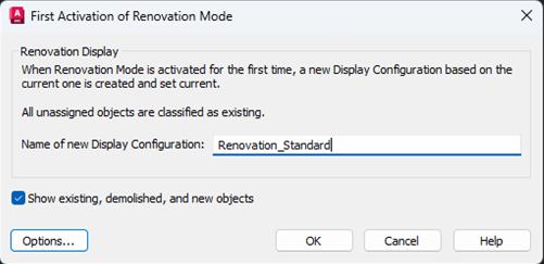
1 – First Activation of Renovation Mode
When working in Renovation Mode and following the recommended workflow, objects are automatically
assigned to Existing, Demolition or New categories. You can assign two-dimensional (2D) and threedimensional (3D) objects to different categories, easily view the drawing as a renovation plan, demolition plan or revision plan, and view objects by category. In plan, section and elevation views, 2D and 3D objects display according to the categories to which they are assigned. The display configurations are controlled by Renovation styles, and these can be customized in the Renovation Options dialog box. With tools on the ribbon you can end Renovation Mode, add objects to categories, and freeze and reset walls to make manual corrections to the edges. This Renovation panel is visible and available only while you are working in an active Renovation session.
Two-dimensional objects, blocks and multi-view blocks keep their own display representation when Renovation Mode is started and are categorized as existing objects. When you delete, modify or create new 2D objects, they display according to the applicable Renovation category. You can explicitly assign them to a category and change their display. Objects that were already categorized in an earlier Renovation phase keep their category and representation. Objects that are created new in active Renovation Mode are automatically marked as New. When an object is selected and a command such as Delete, Move, Rotate or Copy is initiated, objects are assigned to categories and displayed based on the command. For example, pressing Delete identifies objects as Demolition, and moving a door creates both a new and a demolition door and the corresponding wall openings. Existing and New walls automatically clean up with each other, but Demolition and New objects do not interact.
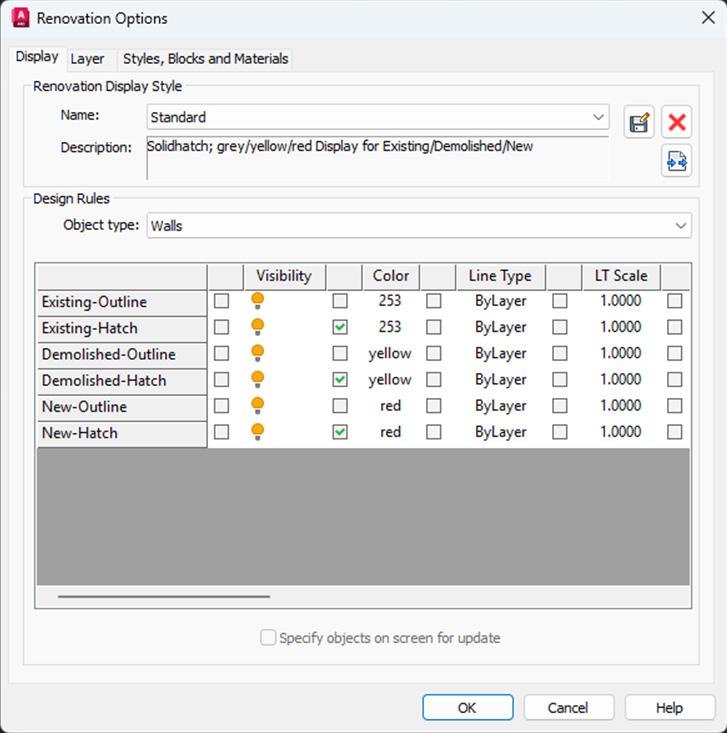
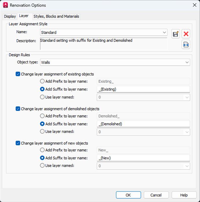
Design rules for New, Demolished and Existing categories by object type are controlled by Renovation styles. You can import Renovation Styles from external catalogs or export to external catalogs in the Renovation Options dialog box. For maximum flexibility, Renovation styles for display and layer assignment can be specified independently from each other and are saved to the current drawing.
In the Renovation Options dialog box, the Display tab allows you to specify the Renovation Display Style as well as set specific design rules for objects such as walls and doors (see Figure 2). The layer tab allows you to set the Layer Assignment Style and specify a prefix or suffix to layers in lieu of changing the layer name (see Figure 3).
The Styles, Blocks and Materials tab allow you to add a prefix or suffix to style/block names to avoid naming conflicts between objects in different Renovation categories See Figure 4). This is much quicker than having to manually rename each object! When the Duplicate Material Definitions box is checked, a copy of the material is automatically generated and assigned to the building object. The corresponding color settings will automatically display.
Once you have finished working in Renovation Mode, ending the session is simple. On the Renovation panel, click the Close Renovation Mode tool (see Figure 5). It is important to note that if changes are made to the drawing after Renovation Mode has ended, the uncategorized objects are automatically assigned to the Existing category when you reactivate Renovation Mode.
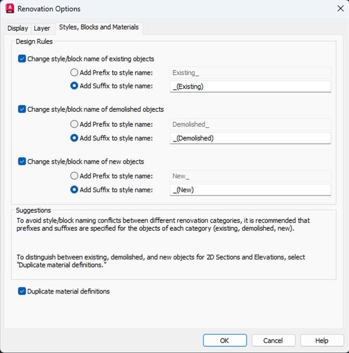
You can change how properties of objects within specific categories are displayed in the drawing by unlocking them, changing them individually per object type and saving them as the Renovation display style. Modifications made are saved to the current drawing. The lock icon to the left of the property signals whether this property can be changed. If the property is unlocked, any changes made to the display are reflected in the drawing,
With the Renovation drawing open in an active Renovation Mode, click Options on the Renovation panel. The Renovation Options dialog box displays. On the Display tab, select the display

style to apply to the current drawing and enter a description. Renovation styles can be modified and saved, deleted, and imported from and exported to an external catalog. Now select the object type for the design rules and then select the checkbox to the left of each property value for the category you want to change. Modify the properties as desired and select Prompt for objects to update. Select the objects to modify or press Enter to select all objects. Changes to the selected properties for the specified object type are applied in the current drawing.
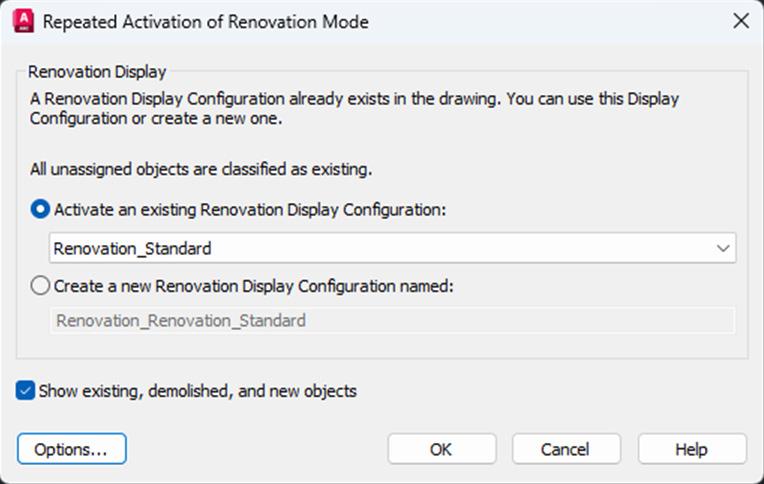
When Renovation Mode is reactivated in your drawing, the existing Renovation display configuration can still be used, or you can create a new one. The objects that were previously categorized in an earlier Renovation phase will retain their representation and category. Any objects that do not yet have a Renovation category will be automatically categorized and displayed as Existing objects. The “Show existing, new and demolished objects” option is automatically selected by default. It is recommended that this option remain selected, as it ensures that categorized objects in your Renovation plan remain visible while switching between the Demolition, Renovation and Revision displays.
To continue working in Renovation Mode, select the Manage tab, then click the Style & Display panel and click Renovation Mode. This will display the Repeated Activation of Renovation Mode
dialog box (see Figure 6). Next you will need to specify the settings in the dialog box, depending on what you want to do. To begin with an existing Renovation display configuration, click the drop-down arrow next to Activate and Existing Renovation Display Configuration, select the display you wish to use and click OK. To begin with a new display configuration, select the Create a New Renovation Display Configuration Named button, enter a name for the new configuration and click OK. Next you can change the display style or design rules of objects by clicking the Options button at the bottom left of the dialog box. Click OK when it’s finished. Then click OK again to exit the dialog box. You are now working in Renovation Mode again.
The display of a demolition plan shows existing construction and those objects categorized as demolished. All new objects, however, are hidden. Display settings for the demolition plan type are located in the options dialog box for Renovation Mode (see Figure 7).
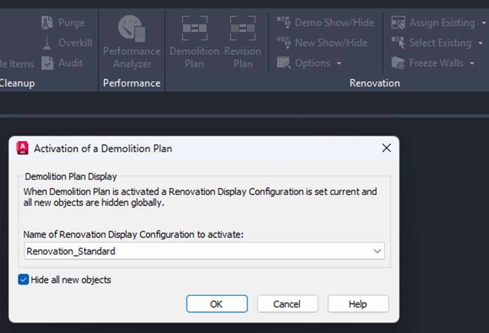
To create a demolition plan, activate Renovation Mode as previously discussed and then select the button for Demolition Plan on the Renovation panel of the ribbon. You can now select a Renovation Display Configuration to activate. The box next to “Hide all new objects” is automatically checked. If you would like for new objects to show while you are working in the drawing, click in the box to de-
select the item and then click OK. You can also click the New Show/Hide button on the Renovation panel. You are now ready to begin a demolition plan. Please note that yellow is automatically assigned by default to demolition objects. This can be changed in the options dialog box for Renovation Mode under the Layer tab.
A revision plan displays new and existing construction objects, but all demolition objects are hidden automatically. Display settings for the revision plan type are located in the options dialog box for Renovation Mode (see Figure 8).
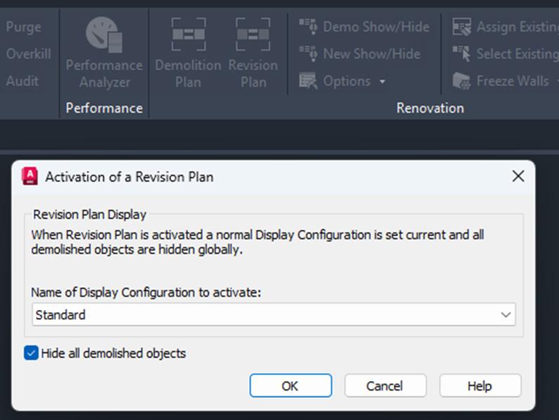
To create a renovation plan, activate Renovation Mode as previously discussed and then select the button for Revision Plan on the Renovation panel of the ribbon. You can now select a Revision Plan Display configuration to activate. The box next to “Hide all demolished objects” is automatically checked. If you would like for Demolition objects to show while you are working in the drawing, click in the box to de-select the item and then click OK. You can also click the Demo Show/Hide button on the Renovation panel. You are now ready to begin creating a revision plan.
Sometimes walls of different renovation categories do not intersect correctly so manual modifications become necessary. This can be done by temporarily suspending Renovation Mode. For example, you may have a plan that includes walls categorized as
Demolition and walls categorized as Existing with wall edges that need to be corrected. Remember, objects categorized as New do not interact with objects categorized as Demolition. When you need to make a manual correction, you temporarily interrupt Renovation Mode by freezing the walls you want to modify and then correcting the edges. These changes are not considered part of Renovation. The option to freeze or thaw walls is only available when Renovation Mode is active.
Let’s make that a little bit clearer. To do a manual modification, click the Freeze Walls button on the Renovation panel of the ribbon. Next select the walls in question and hit Enter. Renovation Mode is now temporarily suspended. Proceed with correcting the wall edges and then click Thaw Walls when finished. Renovation Mode resumes.
The Renovation styles catalog contains display and layer assignment styles. AutoCAD Architecturebased styles for objects are managed with the Style Manager. By default, the Renovation styles catalog is installed in ProgramData\Autodesk\ ACA <version>\enu\Styles. If the Renovation styles catalog is renamed or moved, the styles are disabled and cannot be accessed. Use the Renovation Styles Catalog Settings dialog box to specify a valid catalog.
With the Renovation drawing open in an active Renovation Mode, click Styles Catalog from the Options drop-down menu on the Renovation panel. The Renovations Styles Catalog Settings dialog box displays. Select the “Import renovation styles from catalog” checkbox for drawings to be populated with all Renovation styles in the specified catalog. Clear the “Import renovation styles from catalog” checkbox for new drawings to include standard styles only. Browse to the location of the Renovation styles catalog you want to use. Click OK.

Melinda Heavrin is a CAD Coordinator & Facility Planner in Louisville, Kentucky. She has been using AutoCAD Architecture since release 2000. Melinda can be reached for comments and questions at melinda.heavrin@ nortonhealthcare.org






Ispend a fair amount of my time talking with CAD professionals who are somewhere in the middle of evaluating BricsCAD®. And I am going to be frank with you, what strikes me most in those conversations is not the questions they ask, but the assumptions they carry in with them.
They expect the file compatibility to be messy. They expect their LISP routines to break. They expect an uproar from the users, a loss in productivity, that their standards will need to be rebuilt from the ground up, and they almost always expect to be cut off from the enterprise systems their organization already runs on. The PDM platforms, the PLM environments, and the construction and infrastructure project tools that took years to build and standardize.
Some of those concerns are fair. Most of them are not. Here is what actually surprises teams once they get into a real BricsCAD implementation.
This sounds obvious, but there is a meaningful difference between a file opening and a file working. Most CAD users have experienced opening a DWG in the wrong platform and watching XREFs break, linetypes go missing, or custom hatch patterns render as something unrecognizable.
BricsCAD uses the DWG format as its native file format. Industry-standard DWG. In practice,
external references resolve correctly, sheet sets behave as expected, custom linetypes and hatch patterns display accurately, and the drawing performs the way you built it.
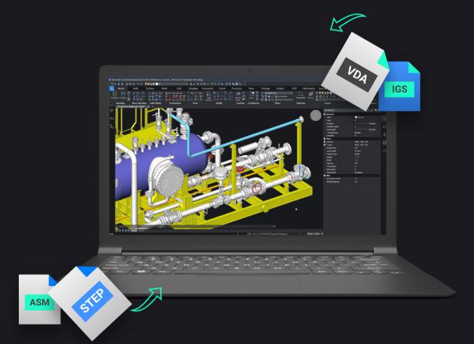
Add in Communicator for BricsCAD to further extend compatibility to 3D, with support for SOLIDWORKS®, Inventor®, CATIA®, Creo®, NX®, STEP, IGES, and many more. For teams working in multiformat environments, this removes a category of problems that has historically required separate software. (See Fig. 1)
The concern going in is almost always the same: we have a PDM platform, a PLM system, or a project data environment that our entire workflow depends on. Will BricsCAD work inside that infrastructure, or will we end up managing files in two separate worlds?
From product data management to construction and infrastructure collaboration to full PLM, BricsCAD V26.2 operates inside your existing environment, not alongside it.
• Autodesk® Vault® integration supports product data management directly within BricsCAD, giving teams better control over their data and workflows without leaving the CAD environment. (See Fig. 2) The Vault connector covers the full range of PDM operations: the Vault Explorer provides direct access from
within BricsCAD, with login and logout, file open options in check-out, check-out-all, or readonly modes, file attachment, and workspace navigation, all built in. File status operations like refresh, check-in, check-out are native to the interface. The control feature set goes further, supporting file property updates, category assignment, lifecycle state management, retrieval of specific revisions, and revision advancement. For teams running Vault as their PDM backbone, these are the daily workflows. Having full control from within BricsCAD
eliminates the context-switching that erodes productivity across a workday.
• Autodesk® Construction Cloud (ACC) integration connects BricsCAD to the ACC environment for smoother AECO collaboration, better data flow, and more connected workflows. BricsCAD operates effectively with ACC through the Autodesk Desktop Connector, and we have ensured compatibility across the workflow’s construction teams rely on most: check-in and check-out, lock and unlock, XRef support, sheet set support, file attachment, BMP rendering,

printing, and publishing within ACC. For teams using ACC as their common data environment, BricsCAD users can participate in that workflow directly. No separate file management process, no manual handoffs. Debating whether BricsCAD works with your ACC environment, the answer is YES!
• Bentley® ProjectWise® integration connects BricsCAD to the ProjectWise engineering content management platform for streamlined AECO collaboration, stronger data control, and alignment with connected industry workflows. For organizations in infrastructure, rail, utilities, and civil engineering where ProjectWise is the established platform of record, this means BricsCAD users can participate in the same disciplined data environment as the rest of the project team.
• Teamcenter® integration: Developed by MechWorks, TCBB connects BricsCAD to Siemens Teamcenter® PLM, managing drawings and revisions from inside BricsCAD, with a smooth transition path for existing Teamcenter users. (See Fig. 3) A dedicated Teamcenter tab in the BricsCAD ribbon provides a direct bridge between BricsCAD as the design system and Teamcenter as the record system. From within BricsCAD, TCBB supports the full document lifecycle: create, revise, and save-as to Teamcenter; check-in and check-out with full status control; metadata synchronization that maps data back and forth between drawings and Teamcenter; X-Ref, OLE, and Data Link support for document hierarchies; smart data search within Teamcenter from the CAD interface; and the Home Browser and Files Status Browser for navigating Teamcenter structure without leaving BricsCAD. For mixed CAD environments, BricsCAD can run alongside a legacy platform within the same Teamcenter infrastructure with no data migration required.
Hundreds of third-party applications have been developed specifically for BricsCAD across disciplines, including AEC, civil, structural, electrical, mechanical, plant design, survey and GIS, facilities management, and more. These are industryspecific solutions built to address the workflows and compliance standards of each discipline, not generic plug-ins.
For implementation teams, this matters practically. Before you build a custom solution or ask a specialty team to change how they work, spend thirty minutes in the catalog. There is a strong likelihood that the tool they depend on already has a BricsCAD version or a direct equivalent. Visit the BricsCAD App Store to discover design tools to further improve your workflow. Implementation gets considerably smoother when the ecosystem your team relies on is already there.
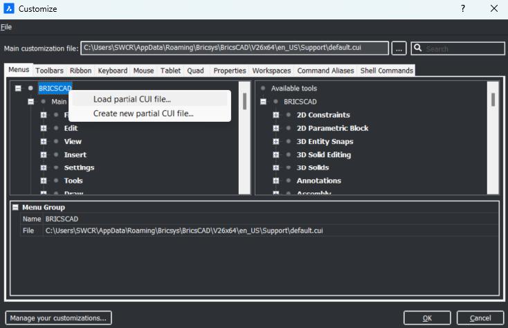
LISP routines load and run without modification in the vast majority of cases. CUI and CUIX files load through MENULOAD, bringing menus and toolbars with them. Custom command aliases are ported directly through the PGP file. (See Fig. 4) Templates, tool palettes, and block libraries are copied to the support file path (or a dedicated location) and are recognized on the next launch.
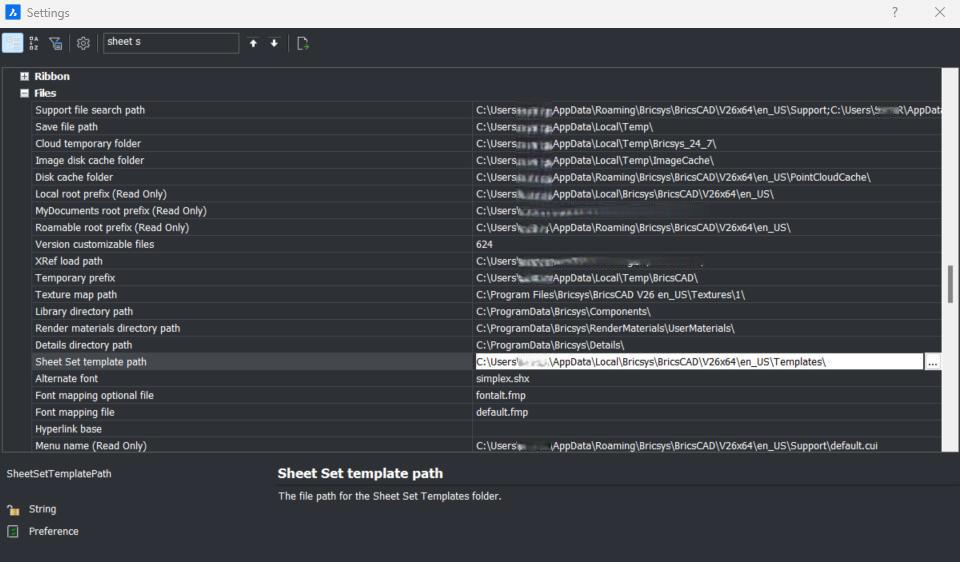
Once configured correctly, the user profiles let you package all of these settings, paths, preferences, workspaces, and startup configurations, etc. into a single exportable file that deploys consistently across an entire team. (See Fig. 5) What takes days to configure manually on individual machines takes minutes when you build it once and distribute it to your team.

Teams with clear leadership and solid CAD standards get through a BricsCAD implementation with minimal and much less disruption. Teams without them struggle. Not because of BricsCAD, but because implementation has a way of exposing gaps that were already there.
The software transition is manageable. What takes more care is establishing buy-in, documenting your company-specific workflows in plain language, and running a structured pilot with real deliverables before the full rollout. Assign two or three experienced users to a self-contained project in BricsCAD first. Their firsthand experience carries far more weight with the rest of the team than any product overview.
The teams that come in expecting disruption often find themselves several weeks into a BricsCAD implementation, running standard workflows, connected to the enterprise systems
they already use, and wondering what they were so concerned about.
BricsCAD implementations succeed because the platform is built to meet organizations where they already are. Once teams experience realworld workflows (DWG files that behave correctly, enterprise systems that stay intact, automations and customizations that transfer cleanly), the conversation shifts from doubt to momentum. What initially feels like a major transition quickly becomes a straightforward upgrade.
For organizations willing to document their standards, empower a few strong users, and run a structured pilot, the payoff is immediate: smoother collaboration, lower licensing costs, and the freedom to modernize without rebuilding years of infrastructure. The hardest part is letting go of assumptions long shaped by legacy CAD platforms.
BricsCAD doesn’t require you to reinvent your environment. It simply gives you a more efficient,
more affordable way to run it. And for many teams, once they see that in practice, they wonder why they waited so long to implement.
Octave BricsCAD® is the true CAD alternative. We are the 2D and 3D CAD alternative that helps you switch smoothly, excel in the detail, and realize better value from day one. Download the free, 30-day trial of BricsCAD. Would you like free lessons? We have that available at BricsCAD Learning. Ready to migrate to BricsCAD? Download the free Migration Guide Follow us today on LinkedIn and YouTube
Octave® provides enterprise software that helps organizations design, build, operate and protect critical industrial and infrastructure assets. Octave supports decisions across the full asset lifecycle where performance, safety and reliability matter and failure is not an option. Octave connects engineering, operational and safety workflows, enabling customers to convert complex operational data into decisions that improve performance,
resilience and incident response across realworld environments. Octave has more than 7,000 employees in 45 countries. Learn more at octave. com and follow us on LinkedIn

Mr. Craig Swearingen is a Global Implementation Specialist and Customer Success Consultant at Octave BricsCAD. Currently, Craig provides migration and implementation guidance, management strategies, and technical assistance to companies which need an alternative, compatible CAD solution. Craig spent 19 years in the civil engineering world as a technician, Civil 3D & CAD power user, becoming a support-intensive CAD/ IT manager in high-volume production environments. Craig is a longtime AUGI member (2009), a Certified Autodesk® AutoCAD® Professional, and he enjoys networking with other CAD users on social media.

DYNAMO ON BORROWED TIME? WHAT AI AND MCP MEAN FOR THE FUTURE OF LOW-CODE
When Dynamo first started making the rounds in AEC, it felt like magic. Yes, I’m a Civil guy, but I would still sit through many Dynamo classes, presentations and demos early on at Autodesk University and other events just to see the power of Dynamo, hoping that one day it would be available for Civil as well to some degree. I always figured that those that truly knew Dynamo, had that early insight and understanding of how much power came with it to automate tasks and make design teams’ lives easier.
Once Dynamo for Civil 3D came around, we could suddenly automate so much! We could automate our corridor modeling workflows, perform clash detections on complex gravity and pressure utility networks, and convert a recently received survey from one standard to another all before lunch. These 3 tasks alone would have taken 1-2 weeks to complete! It was a new superpower, and the barrier to entry felt low enough that non-developers like me could quickly learn it, but still high enough that not everyone would bother to explore the potential.
It’s been a long journey to get to where we are today, which is why I have this lingering thought running through my head lately: “What happens to Dynamo, Grasshopper, GenerativeComponents, and other low code/no code tools like it, if in the very near term all we’ll need to do is put a prompt into an AI agent built directly into the software?” This question gets a lot more real when you look at what’s happening with MCP and agentic AI.
If you haven’t been paying attention to Model Context Protocol (MCP) integrations, now’s the time to start. MCP is essentially a standardized way for AI models to securely read and understand the “context” of your project, allowing them to connect to your data sources and design authoring tools like Revit, Civil 3D, and OpenRoads Designer to see exactly what you see. We’re already seeing early moves from major vendors in this direction, some further along than others, and the trajectory is pretty clear. While MCP provides the context, emerging Agentic AI will allow these models to understand our design intent and take prompted actions inside these applications using specific tool-calling APIs.
Imagine telling your AI agent something like “Create a corridor for alignment “A” using assembly “B” and flag any locations where the daylight intersects the right-of-way.” In the very near term, the AI agent will not only be able to generate the Dynamo graph for us but also execute it. This bridges the gap between the speed of a natural language prompt and the design precision required in AEC. The AI agent handles the complex “wiring,” while the professionals can retain a visible, auditable script. Previously this script would need to have been manually developed by a Dynamo expert.
That’s not science fiction. It’s the reality of where things are heading!
Not quite. In general, AI is only as good as the information we feed into it and have it learn from. From that standpoint, there’s still a very big human element involved and a need for human intervention to perform verification and quality of our designs. The instinct to declare these tools obsolete misses something very important about why they existed in the first place.
Dynamo, Grasshopper, etc. didn’t fully solve automation problems. They did, however, change how designers and modelers think about their workflows. They introduced parametric, logic, and data driven thinking into disciplines that had largely operated on manual, intuition-based processes for decades. To me, it shows that there was a cultural shift paired with a tooling shift.
So, maybe the question to be asking isn’t “will AI replace Dynamo?”, but “What does Dynamo represent moving forward, and can AI replicate that?”
As many of us know, Dynamo represents explicitness. When you build a script or graph, it’s very transparent in the sense that every decision is known and is visible to us. There’s an accountability component baked into this workflow because you can see the logic, audit it, hand it off to a colleague, version-control it, deploy it, and scale it. An AI agent, on the other hand, that “just does it” is essentially a black box by comparison. In AEC, where decisions carry liability, regulatory review, and safety implications, black boxes make a lot of people justifiably very nervous.
My view is that low-code tools like Dynamo won’t exactly disappear, but they will evolve into being relied on as the verification and governance layer that sits between AI-generated actions and production deliverables.
If you think about it, an AI agent might generate a proposed drainage network based on your graded surface and additional design criteria you feed into the AI agent. But before that network or deliverable gets stamped and submitted, someone still needs to validate that the logic was correct and produced accurate results. Furthermore, while AI can “just do it,” a firm requires every project to adhere to specific digital delivery standards. Dynamo graphs will serve as the guardrails, ensuring AI-generated geometry follows the firm’s established standards rather than the AI’s best guess. Because the AI agent processing the prompt is like a black box, that validation is where applications like Dynamo still hold a lot of power.
I might even go as far as to say that AI might actually make Dynamo and those that truly know it more valuable in some ways, not less. If AI agents are generating geometry and data on a scale, we, in turn, need to be building robust checking processes to support automated QA/QC.
And who will be responsible for building these checks? While AI agents will lower the barrier, allowing almost anyone to generate a script via natural language, the responsibility of ensuring that script meets engineering requirements will remain with the experts. If an architect/engineer can put a prompt into an AI agent to design a model, they can just as easily put a prompt into that same agent to create a script and then run it. Very likely, AI agents will be embedded in these low code applications as well, but with that accountability component still being very present and need for a true Dynamo expert to verify and validate.
The group most at risk isn’t the Dynamo power users or the full developers. The risk resides with the middle tier of people who learned just enough Dynamo to be dangerous. These are typically the ones who copy and modify existing graphs without
deeply understanding the logic, and who serve as the “automation person” on their team without that deeper foundation.
If you think about it, if a project manager can prompt an AI agent to do what that person does, the business case for keeping someone in that lane gets thin fast. We’ve seen this pattern before across other industries too, where automation doesn’t just eliminate the bottom of the skill ladder, it eliminates the rungs that exist solely because the technology used to require them.
That said, these professionals are uniquely positioned to evolve into something more like an AI workflow integrator. While a PM can type a simple prompt, the middle skill tier professional understands how to structure complex “agentic” workflows, framing multiple AI outputs and stitching them together into a cohesive project delivery. They already possess that baseline understanding of computational design, how data flows, how lists are structured, and how AEC geometry connects throughout the design process. That foundation gives them a real opportunity to pivot and thrive in this evolving environment.
These are also the professionals who can move from just using automation to truly understanding it. The ones who understand why it works, not just that it works. For engineers/architects, it’ll be those that can look at an AI-generated result and immediately spot the flaw. For designers, it’ll be those who can articulate their intent clearly enough in a prompt for AI to act on it, and then critically evaluate and validate what comes back. From a QA/QC standpoint, if robust automated checking processes are in place, a designer can facilitate cross-disciplinary verification of designs generated from prompts, which starts to flip some of the roles and responsibilities of what we’ve historically done on its head.
As with anything in AEC, the professionals and organizations that can be agile, adaptable and treat this as more than a tooling question are going to succeed. Ultimately, this really isn’t about tooling. It’s way more complex, where workflow, talent, and those that have enough visionary foresight about what expertise is needed to support your
organization in a field that’s increasingly mediated by intelligent systems will be the ones to succeed.
If your competitive advantage today is “we have people who know Dynamo,” you may be left behind very quickly. If your competitive advantage is “we have people who think systematically about design logic, can articulate constraints and intent precisely, and can build and validate automated workflows at scale”, that’s something AI augments rather than replaces.
The tools will change. They always do. What doesn’t change is the need for people who actually understand the problem they’re trying to solve. That’s where the focus and attention should be and will essentially be your secret sauce.
What do you think? Are you already seeing AI starting to encroach on your automation workflows? Or do you think the hype is outpacing reality? Drop a comment! I’d love to hear where your firm is landing on this!

Stephen Walz is the Digital Design Lead for Civil Infrastructure at HDR, a global leader in Engineering, Architecture, Environmental and Construction services. Stephen has been in the AEC Industry since 2003, and with HDR since 2004 working in its northeast and southeast regions. In Stephen’s current role, his primary focus is to work with HDR’s Business, Technical and IT Leadership, as well as our technology vendors, to identify, evaluate and implement new åplatforms/ tools/technologies as it relates to Civil Infrastructure, drive consistency with how HDR is leveraging the various tools and platforms, and identifying ways to build skillsets and overall awareness across HDR to better serve their clients. Stephen can be reached for comments or questions at Stephen.Walz@hdrinc.com

If you spent any time at AUGI CON 26 this year, whether you were in the session on AutoLISP and AI, following the conversation about point clouds and digital twins, or just catching up with peers in the lounge, one theme kept surfacing: the work is getting more demanding. Models are bigger. Deadlines are tighter. And the gap between what the software can do and what your hardware can deliver is widening. That gap is exactly what BOXX was built to close.
APEXX: NEW SILICON. SAME MISSION. AutoCAD®, Revit®, and Civil 3D® are singlethreaded at their core. The hardware that serves them best isn't the one with the most cores, it's
the one with the fastest ones. That's the design philosophy behind every APEXX configuration.
The latest APEXX lineup brings three distinct configurations, each matched to a specific AEC workflow profile:
• APEXX S3- Intel® Core™ Ultra 9 285K | Best for single-threaded CAD responsiveness and viewport speed.
• APEXX A3- AMD Ryzen™ 9 9950X3D | Balanced across modeling, point cloud processing, and rendering.
• APEXX T3- AMD Threadripper™ 9980X |
Built for teams running simulation, large assemblies, or render-heavy pipelines.
We tested the three APEXX models to see which one is best for your workflow. All were benchmarked with the NVIDIA® RTX PRO™ 4000 Blackwell Workstation Edition GPU and 64GB DDR5 memory.
Distributed teams, shared models, remote coordination. These workflows depend on one thing most remote setups get wrong: hardware access.
VDI and thin clients compromise the performance your work requires. BOXX FLEXX doesn't.
FLEXX is a data center-ready platform built for distributed AEC teams:
Revit 2026
Revit 2026
RFO- Render (sec, lower is better)
Revit 2026
RFO- Graphics (sec, lower is better)
Cadalyst AutoCAD 2026: Total Index (higher is better)
Cadalyst
2026:
A few things worth noting from the results:
• The S3 and A3 perform nearly identically on daily modeling and viewport tasks. For most AutoCAD and Revit users, either machine will feel the same in practice.
• The T3's render time of 11.84 seconds is nearly 32% faster than the S3 and A3. If your team is doing heavy visualization or processing large point clouds, that difference compounds quickly across a project.
In keeping with the spirit of this "What's New" issue, we also put Intel's recently released Core™ Ultra 7 processor 270K Plus through its paces, hoping it might offer a competitive price-performance alternative. It's a capable chip, but the Core Ultra 9 285K in the APEXX S3 remained the clear winner for CAD workloads. When it comes to single-threaded performance in AutoCAD and Revit, the 285K remains the Intel benchmark to beat.
• Up to 10 high-density workstations in a standard 5U rack enclosure.
• Liquid-cooled CPU and full size GPU
• Full workstation performance accessible from any connected device.
• Power-only shared backplane- no shared networking, no single point of failure.
• Any module can be inserted or removed without disrupting the others.

Your users in the field, at home, or across offices aren't working on degraded hardware. They're working on APEXX-class performance, streamed to wherever they are.
As AI augmentations layer onto existing CAD and BIM workflows, the performance floor rises. The hardware that's adequate today may not be adequate in eighteen months.
BOXX has spent 25 years building workstations for exactly this kind of inflection point, for professionals who can't afford to have their hardware be the bottleneck.
Visit boxx.com to configure an APEXX workstation or explore the FLEXX platform for your team.

Civil 3D is your engine but pairing it with 2–3 other AEC Collection tools turn it into a full production line that’s faster, more accurate, and easier to manage.
In this article, I’ll walk through practical, lowfriction ways to pair Civil 3D with other tools you already have: Autodesk Docs (Forma Data Management), ReCap Pro, InfraWorks, Vehicle
Tracking, Navisworks, etc. I’ll tailor this towards CAD managers, but any firms, big or small, can take advantage of the “Plus One” mentality. As a CAD manager, you don’t need to turn your team into power users of ten different programs. You do need to define a few core “paired” workflows where Civil 3D stays the primary environment, but other tools quietly handle reality capture, data management, visualization, and analysis in the background.
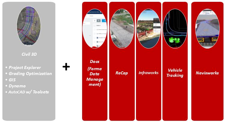
The goal is simple: make the work your team is already doing more efficient, more predictable, and easier to manage on scale.
Civil 3D is still the design and production workhorse for corridors, grading, and plan sets. Your standards, styles, and templates all live there, and that’s not going to change anytime soon. What has changed is the ecosystem around it.
The AEC Collection is designed so models and data move between applications rather than living in isolated DWGs and PDFs.
For most land development shops, the lowesteffort, highestimpact combinations could look like this:
• Civil 3D + Autodesk Docs (Forma Data Management) for controlled project data and reviews.
• Civil 3D + ReCap Pro for accurate existing conditions from scans.
• Civil 3D + InfraWorks for faster concept design and visualization.
• Civil 3D + Vehicle Tracking for integrated swept path checks.
• Civil 3D + Navisworks for easy clash detection.
Civil 3D + Dynamo for endless process automation.
If your project data still lives on a network drive and in email, your team is doing document management manually. Forma Data Management gives you a cloudbased common data environment (CDE) that understands Civil 3D projects and is already part of the AEC Collection.
I wrote a detailed article about the adoption of ACC (Now Forma) in Civil 3D workflows. You can check it out here: https://www.augi.com/augiworld/issue/ january-2026
At a basic level, Forma Data Management gives you:
• Structured folders, permissions, and version control for DWGs, Xrefs, data shortcuts, and PDFs in one place.
• Webbased viewing and markups on drawings and models without needing Civil 3D installed, which means more people can review and comment.
• Civilaware issues and markups originating from Model Coordination and Docs that carry alignment, station, and cutplane context back to the design team.
From a CAD manager’s perspective, the key efficiency gain is reducing friction around “which file, which version, and where are the comments?”. By standardizing Forma Data Management as the home for active project data, you centralize storage, automate versioning, and get traceable reviews, while designers keep working in Civil 3D.
A starting point:
• Stand up a simple Forma Data Management folder structure template for Civil projects (e.g., Admin, Design, Xrefs, DataShortcuts, Sheets, PDFs).
• Move one active job into Forma Data Management and run all formal reviews (internally and externally where possible) through its review workflows.
Capture a before/after on “review cycle time” and number of versioning issues; that’s your internal ROI story.
Most projects live or die on the quality of existing conditions. Traditional survey workflows are not going away, but LiDAR and drones are now common enough that your team needs a consistent way to get that data into Civil 3D. ReCap Pro is your bridge between raw scan data and usable surfaces.
ReCap Pro lets you:
• Import and register laser scans or dronebased point clouds, clean them up, and package them into indexed point cloud projects (RCP/RCS).
Control density, cropping, and segmentation so you don’t overload Civil 3D with unnecessary data.
• Hand off those processed point clouds for direct use in AutoCAD, Civil 3D, and Revit.
Once in Civil 3D, your team can:
Attach ReCap point clouds, create TIN surfaces from them, and extract key features to drive your design base.
• Use those surfaces as the foundation for grading, corridors, and drainage design, backed by highfidelity existing data instead of sparse contours.
Once in Forma Data Management, your team can:
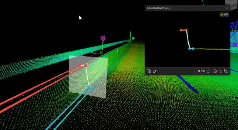
• Utilize point cloud data feature extraction that allows you to extract reference points and linear features, such as a curbs and gutters, from a point cloud dataset.
• Export – All (or part) of your Point Features, Linear Features, or 3D Features, to one of the following exported formats:
• DXF Files (*.dxf)
• LandXML Files (*.xml)
• CSV Files (*.csv)
• These tools are available in the ReCap Viewer within Forma Data Management. Published ReCap point cloud projects have access to these extraction tools in the viewer.
For CAD managers, the win is twofold: you improve accuracy (fewer surprises in the field) and shorten the path from a scan deliverable to a usable Civil 3D surface. Your standards can be specified:
• Where ReCap is required (e.g., complex infill sites, asbuilts, tight utility corridors).
• How point clouds are named, stored in Forma Data Management, and referenced into Civil 3D.
• How surfaces derived from point clouds are classified and labeled in your templates.
Sample Learning: Point Clouds in Civil 3D
Civil 3D is excellent for detailed design but not always the best place to explore alternatives or explain options to nontechnical stakeholders. InfraWorks fills that earlystage gap while maintaining a path back to Civil 3D for detailed work.

With InfraWorks your team can:
• Aggregate terrain, imagery, GIS, and other contextual data into a single model of the project area.
• Lay out conceptual roads, intersections, and grading schemes rapidly, evaluating multiple options with realworld context.
• Exchange data with Civil 3D so preferred options become real corridors, surfaces, and alignments rather than redlines.
For CAD managers, there are two roles InfraWorks can play:
• A quick, visual sandbox for designers to test ideas before investing in full Civil 3D detail.
• A visualization platform where you bring refined Civil 3D corridors and surfaces back in for client, public, or stakeholder presentations.
You don’t need every designer to live in InfraWorks. You need a clear workflow for when it is used, how models are stored in Forma Data Management, and how data moves back to Civil 3D so you don’t end up with disconnected models.
Sample Tutorials: Introduction to Infraworks
Swept path checks are nonnegotiable on most land development projects: fire access, delivery vehicles, school buses, refuse trucks. Many teams still handle this with external tools or manual approximations, which makes it hard to standardize and audit.
Vehicle Tracking gives you:
• A library of design vehicles and tools for swept path analysis embedded directly in Civil 3D and AutoCAD.
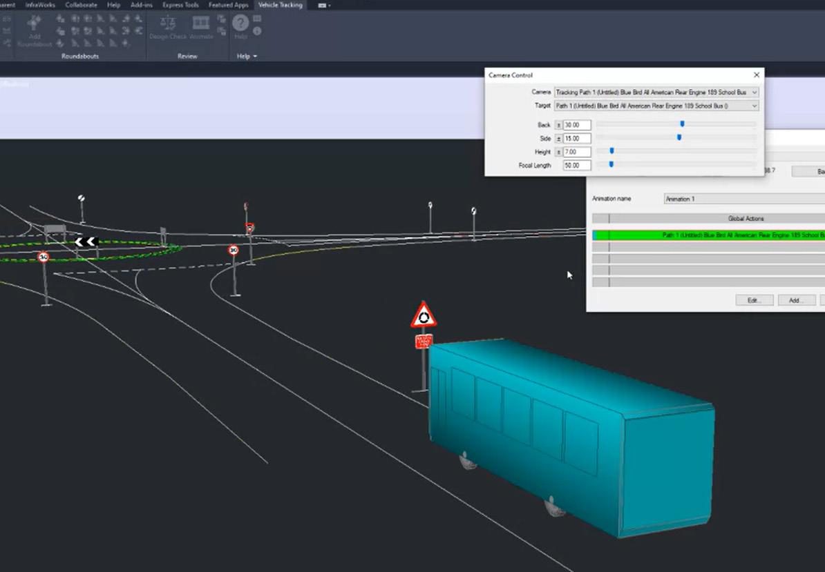
• The ability to analyze vehicle paths through roundabouts, site entrances, parking lots, and internal circulation routes tied to your geometry and corridors.
From a CAD management standpoint, Vehicle Tracking is less about “cool analysis” and more about embedding a repeatable QA step into your design templates and checklists. You can:
• Define which design vehicles are required for standard project types in your CAD standards.
• Provide predefined styles and layers for swept path graphics so they plot consistently.
• Make swept path checks a formal part of your internal review process, not an optional extra.
This keeps review effort and risk down while giving you clear evidence that access and maneuvering have actually been checked, not assumed.
Sample Tutorial: Swept path analysis with Vehicle Tracking in Civil 3D
You can absolutely use Navisworks to clash-check Civil 3D object (corridor, pipes, etc) exports; the key is exporting in a way Navisworks can reliably read, then setting up smart clash tests and tolerances. In just a few simple steps, coupled with very simple CAD standards and settings, you’re minutes away from clash checking just about anything in Civil 3D.
Focus on getting a “clean” Civil 3D file before export:
• Use a dedicated Navisworks export drawing with only the relevant corridors, surfaces, and pipe networks data-referenced in, not your working file.
• Make sure the corridor model is fully rebuilt, with appropriate code set styles so all key elements (pavement, subgrade, daylight, etc.) display as 3D solids or surfaces.
• Turn off or freeze nonessential layers so they don’t clutter the Navisworks model; only visible objects export via NWC.
For checking corridor vs. utilities (or gravity vs. pressure networks), ensure utility networks are modeled in 3D with correct elevations (gravity pipes, pressure pipes, or 3D solids).
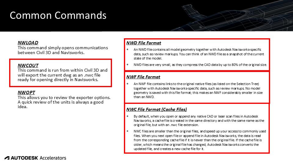
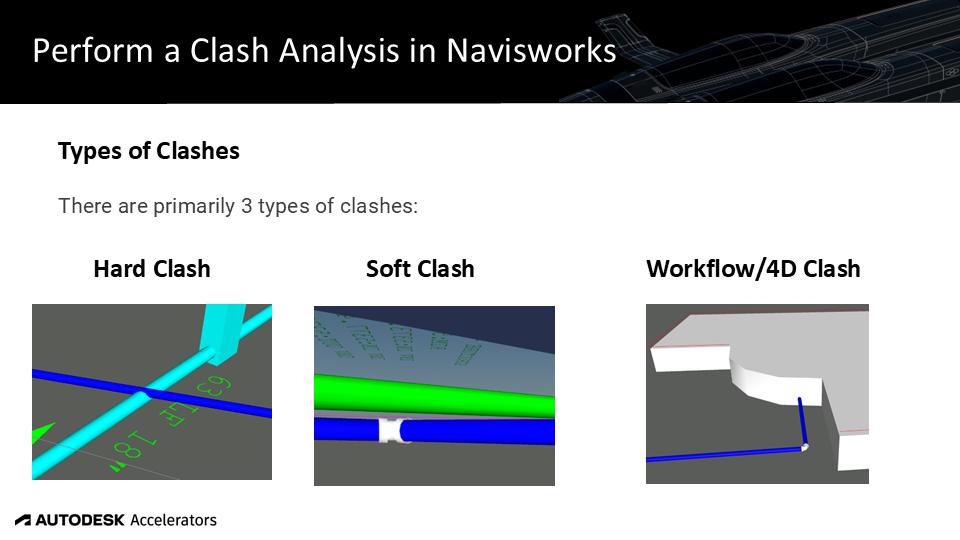
Use the built-in exporter so Navisworks reads Civil 3D geometry correctly:
• In Civil 3D, run NWOPT to review exporter options and verify units and coordinate handling are correct.
• With only the needed objects visible, run NWCOUT and save the corridor model to an .NWC file in your project location.
• The exporter will include Civil 3D objects, surfaces, and xrefs that are visible in the current view, so use layer control to manage what goes across.
Repeat this as needed for other discipline models (e.g., structures, MEP, utilities, Revit models) if they are not already in Navisworks.
In Navisworks Manage:
• Append your Civil 3D corridor NWC along with utility, structural, and any Revit or IFC models into a single coordinated model.
• Verify coordinate alignment (shared coordinates / project base) so the corridor aligns properly with utilities and structures.
• Use Selection Sets to group objects: e.g., “Corridor - Pavement & Subgrade”, “Existing Utilities”, “Proposed Utilities”, “Structures”.
This makes it much easier to create targeted clash tests (corridor vs. utilities, subgrade vs. structures, etc.).
Use Clash Detective in Navisworks Manage to compare corridor elements against other systems:
• Create a new clash test (e.g., “Corridor vs Proposed Utilities”) and set Set A = corridor solids/ surfaces, Set B = pipe/utility networks or 3D solids.
• Apply appropriate tolerances (clearance values) using clash rules and tolerances so you can check either “hard” clashes or maintain a buffer (e.g., 1 ft vertical clearance).
• Optionally, enable rules such as “Ignore items in the same layer” or discipline-based rules to reduce false positives.
Run the clash test to generate clashes and use viewpoints/comments to document issues; you can then export clash reports or integrate with ACC/ Navisworks issues for tracking.
A few practical tips when using Navisworks for corridor clashes:
• If corridor components come through as surfaces instead of solids, consider extracting corridor solids in Civil 3D (e.g., for pavement, subgrade) so clashes behave more predictably.
• Use a simplified style for the “Navisworks export” drawing: no contours, labels, or unnecessary linework, just 3D design geometry and key references.
• For pipe networks, you can still use Civil 3D’s Interference Check for quick checks, but Navisworks gives you a more holistic, multi-discipline clash environment and better reporting.
Simple Tutorial: Export a road corridor from Civil 3D to Navisworks
As you may know, the opportunities in Dynamo are almost endless!! There’s a ton you can do, and there’s been some awesome AUGI articles on Dynamo. One of my favorites recently was written by Lukas Drbohlav on “Property Sets for Pipe Networks in Civil 3D 2026 and how to Extend Them with Dynamo”.
Here’s a link to that article: https://www.augi.com/ augiworld/issue/february-2026.
You have three main Dynamo-based alternatives: pure Dynamo clash scripts inside Civil 3D, paid “off-the-shelf” Dynamo graphs, and hybrid workflows that pull clash data from Navisworks back into Civil 3D for visualization and resolution.
Dynamo for Civil 3D can directly compare geometry in the DWG and flag both hard and soft clashes without leaving Civil 3D.
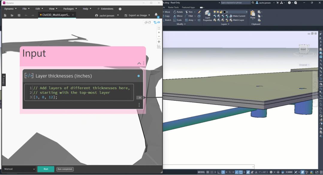
Typical scripts:
• Compare 3D solids (e.g., corridor solids, Revit imports, structures) against pipe networks and drop a marker/solid at each clash location.
• Compare gravity vs. pressure networks, identify where separation falls below a set clearance, and place nodes or solids on a dedicated “CLASH” layer.
• Use a clearance parameter so the script reports either physical intersections or proximity below your standard (e.g., 1 ft vertical).
These are great when you don’t have Navisworks Manage licenses but you still want repeatable clash analysis embedded in design workflows.
Several consultants sell ready-made Dynamo scripts targeted at Civil 3D clash work:
• Utility Clash Detection scripts that check clearances between networks and place markers for clashes with user-defined separation values.
• “Clash Detection with Clearance Values” that supports corridors, utility networks, Revit-derived solids, and other 3D geometry, dropping 3D markers wherever clashes occur.
• Gravity-pipe-only clash detection graphs that take two pipe groups, a clearance value, and layer name, then draw circles at clash locations.
These can save time if you don’t want to build and debug your own graph library, especially for standard gravity/pressure network checks.
Learn Dynamo: https://primer2.dynamobim.org/ dynamo-for-civil-3d
You can also use Dynamo to post-process Navisworks clash results back in Civil 3D:
• Some scripts read a clash report (coordinates) exported from Navisworks, then place circles or markers at those coordinates directly in the Civil 3D model so designers can see clashes in context.
• Other custom graphs focus on automatic clash resolution, for example shifting pipes
horizontally to remove multiple clashes in one run based on defined rules.
This hybrid approach keeps Navisworks as the clash “engine” but uses Dynamo to automate how results are visualized and addressed in Civil 3D.
Compared to alternatives:
• Civil 3D’s native Interference Check works for gravity pipe networks only and is limited in automation/reporting.
Navisworks offers richer clash rules, multi-discipline 3D context, and coordination with ACC, but adds steps and relies on external software.
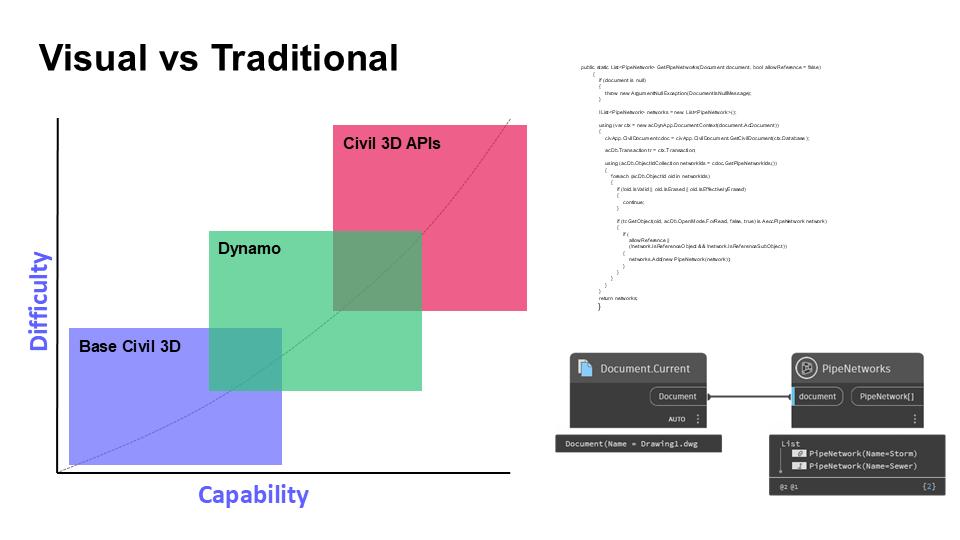
• Dynamo gives you customizable, in-model clash checking, can include both gravity and pressure networks and arbitrary 3D geometry, and can embed your firm’s clearance rules directly into scripts.
CAD and BIM managers are usually the ones accused of “throwing new software at people.” The reality with the AEC Collection is that you already own the software; what’s missing is a deliberate, phased rollout.
A practical roadmap could look like this:
1. Pick one workflow pair to pilot. For most land development groups, that’s Civil 3D + Autodesk Docs or Civil 3D + ReCap Pro.
2. Define success in operational terms. Examples: fewer lost files, faster review cycle, fewer toporelated RFIs, better asbuilt capture.
3. Document a simple, twopage workflow. Where files live (Docs structure), who does what, and when the secondary tool enters the process.
4. Run one live project through the new workflow. Keep training focused: “Here is exactly how this project will work,” not “Here’s everything Docs/ReCap can do.”
5. Capture metrics and feedback. Use that to refine your standards and justify rolling the workflow out across more projects.
Only after that first pairing is stable should you add the following: maybe InfraWorks for concept work on larger sites, or Vehicle Tracking where access and circulation are complex.
The AEC Collection will not magically make your Civil team more efficient just because it’s installed. The real leverage comes from a small number of welldesigned workflows where Civil 3D remains the primary environment and other tools quietly support the lifecycle around it: capturing reality, managing data, exploring options, and validating design decisions.
Your role as a CAD manager is to:
• Decide which workflows matter for your firm’s projects.
• Standardize how those workflows are executed, documented, and supported.
• Measure the impact so you can prove the value of doing more than just “Civil 3D plus a file server.”

Shawn has been a part of the design engineering community for roughly 20 years in all aspects of design, construction and software implementations. He has implemented and trained companies across the Country on Civil 3D and other infrastructure tools and their best practice workflows. Shawn can be reached for comments or questions at sherring@ prosoftnet.com.
Let me introduce myself. Some of you may already know me. My name is Shaun Bryant, sometimes affectionately known as ‘CADjedi’ or ‘SCB’. I have recently assumed the mantle of authoring Inside Track (for the second time). After a conversation with Todd Rogers (Editor-In-Chief), I requested that we take Inside Track in a different direction, so that we offer YOU, the reader, the INSIDE track.
I have been using CAD for 38+ years (primarily AutoCAD), but I have also had professional experience of the AutoCAD specialised toolsets, such as AutoCAD Architecture, AutoCAD Electrical, and AutoCAD Mechanical, to name a few. I have also managed the Revit function of a highly respected UK architect’s studio. I also have experience and expertise with BricsCAD and DraftSight. I have over 90 AutoCAD titles in the LinkedIn Learning library, and I’m an Autodesk Certified Professional. I have spoken at Autodesk University for the last nineteen years (yep, 19) and last month (February), I delivered my first DraftSight class at 3DEXPERIENCE World 2026 (3DXW26) in Houston, Texas.
It’s with that experience and expertise that I want to offer you the INSIDE information. The INSIDE Track. Those tips, tricks, and workflows, that might not even involve software applications. I have been there, done it, and you’ll often see me wearing the T-shirt. I want to pass on what I know so that you can work smarter, not harder. I also hope you’ll always be learning from INSIDE Track, as I believe we ALL have value, and should be given the opportunity to learn and obtain the knowledge we need to move forward.
Here goes…
It’s very easy to get into the same routine. I was a CAD manager for nine years, and trust me, it could have easily just been a 9-5 getting the drawings out by 5pm on a Friday before the weekend. But I didn’t want it that way. I was the young upstart at my company at the time. Early twenties, first drafter to be sent on an AutoCAD training course. My boss saw promise, and within a year, I was running the CAD
function, looking after twenty-five drafters, some still on the drawing board, some straight on to AutoCAD. I wanted to make the CAD function a shining light for the company. It was my responsibility to do so. Here’s a condensed version of how I did that.
The company I worked for was the special operations branch of a large petro-chemical organization. Projects were worked on all over the world. Different time zones, different drawing delivery times, you name it. The internet boom was just kicking in, and we had just had ADSL installed at the office. I developed a shift system to make sure we had 24/7 CAD team coverage Monday through Thursday, with a team leader for each shift. The team leaders reported to me during a Friday morning meeting with progress. The team leaders were able to use email to communicate with their peers working locally all over the world, and send drawings, revisions, and variation orders day-on-date, at local project time. This not only kept projects current but made sure that drawings were delivered ahead of project milestones, building more efficiency and productivity within the company.
My first AutoCAD training course set me on a path to where I am today. I’ll always remember my instructor, Andy Coulson, who taught me the intricacies of AutoCAD (Release 12, I think – it’s been a while). I could see how getting everyone off the drawing board and in front of a CAD workstation would further enhance the CAD function of the company. I made a business case to higher management to get my remaining drafters trained up on AutoCAD. But I didn’t just ask for the budget for the training. I sat down with my drafters still on the board, and monitored times taken for drawings to be revised and/or completed. I then got my trained AutoCAD drafters to replicate the same drawing workflows. A comparison of the times was made to get an idea of how much quicker this was. That was then aligned with the costs of the training, to get an approximate Return On Investment (ROI). At the time, it made the
CAD function about 65% more efficient. A no-brainer, you might say. Suffice to say, management approved the AutoCAD training. That said, I then build in a bi-annual training budget request for training on new versions of AutoCAD and other associated applications (ArcGIS was one back in day). Your CAD function is only as good as the knowledge of your CAD team. My argument is this if management countered a training budget request: -
Management: “What happens if we train them and they leave?”
My counter: “What happens if we DON’T train them and they STAY?”
As a content creator, instructor, and author, I cannot stress this enough. Learning is continuous. It should not stop for you, or for your team. Fight to learn if you must, create the appropriate business argument, such as my ROI example above. But ALWAYS be learning.
I mentioned this earlier. Initially, this was set up for my team leaders to report back to me, but it developed into a lot more. Once the reporting was completed, the meeting often became a couple of hours to discuss the overall CAD function and how improvements could be made. I decided to leave it as an ‘open door’ session so that all my CAD team could feel comfortable to stop by and talk about individual requirements, such as training, appraisals, and ideas about how to make processes and workflows more efficient. This is where I learnt a valuable CAD managerial skill. Listening. Your CAD team are your bedrock. Their opinions MATTER. Their expertise is what keeps the wheels turning. LISTEN to your team, and take it all in. Make sure you set up a specific day and time for that information download. Trust me, many a new workflow was put in place after one of those meetings that made the CAD function productive, and profitable. It also made the CAD team members feel valued as part of a cohesive team.
As you have probably gathered, this month’s INSIDE Track has a bias towards CAD
management and my experience of that. I hope, during my tenure, I was a good CAD manager. For all you CAD managers out there, I do hope that these witterings of mine will give you some ideas for your CAD management and allow you and your CAD team to improve and inspire each other to develop and move forward.

Shaun ‘CADjedi’ Bryant is a seasoned CAD and BIM veteran with over 38 years of experience in the industry. As a CAD subject-matter expert and instructor with practical experience in AutoCAD, BricsCAD, DraftSight, and Revit, Shaun creates clear, structured learning content that helps engineers and designers understand complex CAD and BIM workflows and apply them effectively in real project environments. He is known for breaking down detailed engineering processes into content that has helped over half a million learners strengthen core CAD skills, improve workflow efficiency, and communicate technical information more effectively.
Alongside his instructional work, Shaun advises organisations on improving CAD communication standards and building stronger capability frameworks within technical teams through his company, CADFMconsultants. He also a huge advocate for user communities such as AUGI, building resilient connections between application vendors and their users.
Shaun is also the owner of the Not Just CAD brand that includes The Not Just CAD blog and podcast. He is a true techie geek and runs CADFMconsultants // Not Just CAD from ‘The Workshop’ in East Yorkshire in the UK.
If you have some news to share with us for future issues, please let us know. Likewise, if you are a user of a featured product or news item and would like to write a review, we want to know. shaun.bryant@cadfmconsult.co.uk