
HPAC - Modern Hydronics Spring 2026

Page 1


MODERN HYDRONICS

SPRING 2026

GEO SYSTEM FIX HEAD ENERGY FACTS COASTING MODE

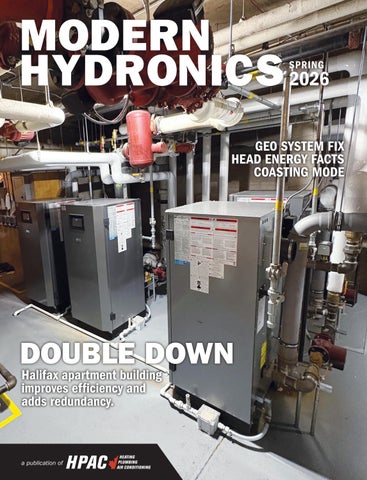
DOUBLE DOWN

Halifax apartment building improves efficiency and adds redundancy.

Navien introduces its full line of HVAC products, featuring new NAZ Heat Pumps, NAS Air Handlers, NAM Cased Coils, and other forced-air components. Deliver a whole-home AHRI matched Navien comfort system when pairing with the NPF Hydro-furnace, including a powerful dual-fuel system with gas-powered NPF and the NAZ Heat Pump.

To learn more about Navien HVAC comfort, visit us at navieninc.com NEW NAZ Air-to-air heat pump inverter-driven heating and cooling systems

MH4

GEOTHERMAL Heat Pump Hiccups

Reviewing a problematic geothermal/boiler system design and proposing a fix.

By John Siegenthaler

MH8

30 MECHANICAL MINUTES

Head Energy

In this episode John Siegenthaler walks us through the concepts behind head energy in closed-loop hydronic systems.

MH10

INSTALLATION

Double Up

Halifax apartment complex retrofit replaces two boilers with four for greater efficiency and redundancy.

By Thomas Renner

MH18

MH14

INTEGRATED DESIGN EFFICIENCY IN EVERY DROP: PART 4

Retrofitting buildings with high efficiency hydronics solutions to meet decarbonization targets.

By Zachary Londo, Jean-Claude Rémy & Chris DesRoches

BUILDING BLOCKS DISTRIBUTED COMFORT

The first of a six-part series on the fundamentals of hydronics to boost general hydronics knowledge in the plumbing and heating industry.

By Michael Breault

H20 DESIGN Keep It Flowing

Allowing water in a circuit to keep moving is an antifreeze alternative to prevent potential freezing in concrete slabs.

By John Siegenthaler

MODERN HYDRONICS

EDITOR

ASSOCIATE PUBLISHER

NATIONAL ACCOUNTS

ACCOUNT COORDINATOR

MEDIA DESIGNER

CIRCULATION MANAGER

PUBLISHER

CEO

Doug Picklyk (416) 510-5218 DPicklyk@hpacmag.com

David Skene (416) 510-6884 DSkene@hpacmag.com

Amanda McCracken (647) 628-3610 amccracken@hpacmag.com

Kim Rossiter (416) 510-6794 KRossiter@hpacmag.com

Emily Sun esun@annexbusinessmedia.com

Urszula Grzyb (416) 442-5600, ext. 3537 ugrzyb@annexbusinessmedia.com

Peter Leonard (416) 510-6847 PLeonard@hpacmag.com

Scott Jamieson

HEAT PUMP HICCUPS

Reviewing a problematic geothermal/boiler system design and proposing a fix.

An installer is asked to create a three-zone radiant floor heating system using a 5-ton (60,000 Btu/h) single-speed geothermal water-to-water heat pump as the primary heat source, and a mod/con boiler as the auxiliary heat source.

The heat pump is supplied by four earth loops made of 1-in. HDPE tubing, with each loop being 500 feet long. Each earth loop passes through the foundation and is manifolded inside the building.

Each of the three zones will have a sixcircuit manifold station with nearly identical circuit lengths. All the floor heating circuits are underfloor tubing with aluminum plates stapled tightly to the underside of the subfloor and well insulated.

The designer sets up a primary sec -

ondary system where each heat source connects to the primary loop using a pair of closely spaced tees (as shown in Figure 1 above).

Each manifold station is also supplied from a pair of closely spaced tees installed in parallel “crossovers” of the primary loop. The designer did this to keep the supply water temperature to each manifold station equal. The system has seven identical 1/25 HP circulators.

Two ¾-in. boiler drain valves installed at the ends of the interior headers serving the earth loops are used for filling and purging the earth loop circuits.

The two heat sources are controlled by a two-stage setpoint controller. When there’s a demand for heat from any of the zones that controller looks at the temperature at the supply temperature sensor (Ts), and uses the following logic:

Stage 1: If Ts ≤ 115F then heat pump = ON; If Ts ≥ 117F the heat pump = OFF

Stage 2: If Ts ≤ 112ºF then boiler = ON; If Ts ≥ 125ºF the boiler = OFF

However, when put into operation the heat pump is short cycling, the boiler

runs much longer than the heat pump, and the owner becomes increasingly upset with both the frequent cycling of the heat pump and the amount of natural gas consumed by the boiler, especially considering that the latter was only supposed to operate as a backup to the geothermal heat pump.

SHORT CYCLING DILEMMA

There are several details that are either wrong or have alternatives that will improve the performance of this system.

Following is my list of suggestions:

1) A 1/25 HP circulator might be adequate for a zone, but it’s not going to have sufficient flow and head to adequately supply the earth loop connected to a 5-ton heat pump. Minimum earth loop flow is often established based on maintaining turbulent flow, which enables good convective heat transfer. For a 1-in. HDPE pipe operating with 25% solution of propylene glycol antifreeze, and a minimum loop temperature of 30F, that flow needs to be about 5 gallons per minute (gpm) per loop. Thus, the overall flow

Figure 1. Example of a geothermal and boiler primary secondary system where each heat source connects to the primary loop using closely spaced tees.

passing through the heat pump is about 20 gpm. There’s no way a 1/25 HP circulator is going to come close to this requirement, especially when considering head loss through the earth loop circuits and the heat pump.

2) There’s no air separator or expansion tank in the earth loop. Both are needed for optimum performance and minimal pressure variation in any closed loop hydronic system.

3) As shown in Figure 1, all earth loop circuits must be filled and purged simultaneously. While possible, this requires much more flow than can be forced through typical boiler drain valves. Purging an earth loop of this size requires a flow of at least 16 gpm (4 gpm per loop). The valves used to force flow through this configuration should be at least 1.25-in. full port ball valves.

4) Both circulators on the heat pump are “pulling” flow through their respec -

tive heat exchangers (e.g., the heat pump’s evaporator and condenser). Some coaxial heat exchangers used in heat pumps have relatively high flow resistance, which creates high pressure drops when operating at the required flow rates. This situation could cause the circulators to cavitate, especially if the static pressure in the earth loop is low. It’s always better to locate circulators so that they “push” flow into high flow resistance components. The same holds true for the boiler circulator.

5) The controller on/off settings for stage 1 are much too close, especially for a low thermal mass radiant panel. This likely causes the short cycling.

6) The temperature at which stage 2 turns off the boiler is several degrees higher than when the heat pump turns off on stage 1. This causes the boiler to remain on and likely drive more heat into the distribution system than necessary,

SIMPLY GENIUSTM

which could lead to an overshoot in room temperature. It also increases natural gas usage relative to what is necessary.

7) The expansion tank is poorly placed relative to the primary loop circulator. It pumps water toward rather than away from the point where the expansion tank connects to the system. This will cause the primary loop pressure to drop when the primary loop circulator is on, again leading to the possibility of cavitation.

8) Two of the purging valves on the radiant branch circuits are upside down.

9) There’s no pressure relief valve in the system. All closed loop portions of any hydronic system with a heat source should also have a pressure relief valve.

10) There will be some flow imbalance between the manifold stations due to the use of direct return distribution piping. The zone 1 crossover will get more flow than that of zone 2. The zone 2 crossover will get more flow than zone 3. Balancing

valves need to be used in each crossover connected to direct-return piping mains, especially when the supply and return mains are long as would likely be the case with all three manifold stations.

11) The supply temperature sensor for the staging controller should be downstream of both heat sources. As shown in Figure 1 it senses heat input from the heat pump, but not (directly) from the boiler. If the room thermostat wasn’t satisfied quickly, this would keep the boiler on until the return water temperature climbed a few degrees above 125F.

12) The air separator should be available to both heat sources, not just the boiler.

13) The location of the backflow preventer and pressure reducing valve on the make-up water system is reversed. The backflow preventer should always be installed upstream of the pressure reducing valve.

14) There is no way to isolate either heat source from the remainder of the system if necessary for service.

RIGHTING THE WRONGS

There are multiple ways to correct the errors discussed above. Rather than addressing them individually, Figure 2 (next page) shows a system configuration that eliminates them all.

Both heat sources can operate individually or in parallel supplying heat to a buffer tank. The mass of the tank stabilizes the system against short cycling.

The temperature of the buffer tank is controlled by a two-stage outdoor reset controller rather than a setpoint control.

The heat pump is the fixed lead heat source, and the boiler the fixed second stage. As the outdoor temperature increases the temperature of the buffer tank is reduced. This increases the heat pump’s COP and the boiler’s efficiency.

The distribution system is zoned with valves and supplied by a pressure-regulated variable speed circulator. This reduces circulator count and greatly reduces the electrical energy required to operate the distribution system.

Each manifold station is supplied by home run piping. The headers supplying each branch of the distribution system are as short as possible and generously sized (maximum flow velocity of 2 feet per second).

The headers are also configured as reverse return. This combination of details, and the fact that all three manifold stations are identical, eliminates the need for balancing valves.

Each heat source can be isolated from the remainder of the system if necessary for service.

Check valves are used to prevent flow reversal or heat migration through either heat source when it is off.

If you sell, service or specify hydronics products you need to attend the 11th edition of the Modern Hydronics Summit.

Whether you’re a hydronics newbie or an established “wet head” the Summit is the place-to-be to step-up your hydronics game.

Here’s why you’ll want to attend:

• See all the newest in hydronics technologies

Hydronics 101 sessions are sponsored by - perfect for newer technicians!

Master Class sessions are sponsored by - designed for experienced pros!

• 3 educational session levels

• Hydronics Haul-away prize packages

• A chance to win Blue Jays tickets and test instruments

• Sweet Heat Installation Contest winners announced

• And so much more!

in exhibiting?

A combination air/dirt separator and expansion tank have been added to the earth loop system.

Each earth loop can be isolated by ball valves, allowing for faster filling and flushing.

A pressure relief valve and properly configured make-up water assembly have been added to the system.

The earth loop circulator is pumping away from the expansion tank and thus increasing pressure in the earth loop circuits and heat pump evaporator when operating.

BEFORE PICKING UP THE TOOLS

Small details are easy to overlook. When you review plans for an upcoming system remember to check all the basics such as hydraulic separation of circulators, pressure relief, proper location and sizing of expansion tanks, isolation valves, purging provisions and controller settings.

It’s a lot easier, and a whole lot less expensive, to spot these details and correct them in the planning or review stage compared to changing components on-site with a frustrated customer looking over your shoulder. <>

John Siegenthaler, P.E., has over 40 years of experience designing modern hydronic heating systems and is the author of Modern Hydronic Heating (4th edition) and Heating with Renewable Energy (visit hydronicpros.com).

Figure 2. Eliminating all of the potential errors from the design in Figure 1

OHEAD ENERGY

In this episode John Siegenthaler walks us through the concepts behind head energy in closed-loop hydronic systems. BY DOUG PICKLYK

n January 13th HPAC magazine was joined by contributing writer John Siegenthaler for another episode of 30 Mechanical Minutes, the free webinar series. This edition featured a discussion on the concept of head energy in closedloop hydronic systems. The educational episode was sponsored by PEXhouse. com, Canadian online wholesaler for plumbing, heating and hydronics.

Registrants to the live webinar were asked how they would define “head” in a hydronic system. From the 167 responses, roughly 40% referenced the pressure required to circulate fluid through a system, while 25% referred to resistance, as in the head is resistance to flow or friction. Another 20% equated head to height, either the actual height within a system or the energy needed to lift water a certain height. And others thought head had to do with the weight of the water in the circuit.

Siegenthaler was amused at the variety of answers and admitted, “Most of them do have some relationship to what head and differential pressure are in a system, but none of them are really complete or concise.”

So, he shared his definition: “Head in a hydronic system is the mechanical energy contained in a fluid.”

He then went to explain how mechanical energy exists in many different forms, like kinetic mechanical energy (any object that’s moving has kinetic energy), and potential energy that has to do with elevation above the ground.

He then brought up the first law of thermodynamics: “Energy cannot be created or destroyed, only changed in form.”

For example, when stopping a car, applying the brakes converts kinetic mechanical energy into thermal energy.

“In a hydronic application, a circulator converts electrical energy into mechanical energy, and we just happen to call that energy head,” he explains.

He notes there are three different ways mechanical energy can manifest in a fluid. When a fluid is under pressure it has pressure mechanical energy. If it’s moving it has kinetic energy. And if it changes elevation, it’s changing its potential energy.

He then referenced Daniel Bernoulli, a Swiss physicist from the 1700’s, who came up with the equation that adds up these different forms of mechanical energy to arrive at the total energy, or head, in the fluid.

“If we could imagine an ideal hydronic system that had a frictionless fluid (and there’s no such thing as a frictionless fluid), and you could somehow start the fluid moving through that hydronic system, you could completely turn off any circulator and the fluid would circulate forever,” says Siegenthaler.

However, he points out that in any real system there’s going to be friction between the fluid and the surfaces of the components the fluid moves through, and that’s going to dissipate that mechanical energy.

“So that’s why we have to keep a circulator running,” he says, “We’re re-injecting energy.”

He then invited attendees to go through a thought experiment. Picture a 1-in. diameter copper pipe leading into a circulator, and a 1-in. pipe exiting the circulator. The flow rate coming into the circulator is 10 gallons per minute (gpm), and the temperature of the incoming water is 100F, and the pressure at the inlet of the circulator is 10 psi.

The circulator is running, and he asks: “Has the water’s flow rate increased leaving the circulator?”

The answer is no. If you have 10 gpm coming in, you have 10 gpm going out. In a closed-loop hydronic system the flow rate stays the same through the system.

Next question: “Is the water velocity higher leaving the circulator?”

It’s a 1-in. pipe in, and a 1-in. pipe out, so the answer is no. The velocity is not any faster.

Next question: “Has the water’s temperature increased going through the circulator?”

A purist might say yes, as there is some friction inside a circulator, but it’s insignificant. So, from a practical standpoint there is no heat gain.

Final question: “How do we know head energy is being added to this water?”

The answer is revealed at the pressure

gauges. An increase in pressure is the evidence that head energy is being added. Like a thermometer measures thermal energy changes, pressure gauges measure change in head energy.

“We can actually calculate the amount of head energy added if we know the pressure increase,” says Siegenthaler.

Using a formula, he shows how head energy is measured in feet. “Think of head as the number of foot-pounds of mechanical energy that’s been added to each pound of fluid as it’s going through the circulator.”

When asked, “What’s the purpose of increasing the pressure in the fluid?”

“Well, water is always going to flow from higher pressure to lower pressure, so when we have a higher pressure at the outlet of the circulator, the water’s going to move away from the circulator and ultimately towards the inlet of the same circulator. You can think of the dif-

ferential pressure that has developed as the impetus for flow.”

A circulator is the only device in a hydronic circuit that adds head energy, and everything else the fluid goes through (pipes, fittings, valves, heat exchangers, heat emitters, boilers, heat pumps, etc.) dissipates that head energy. Adding up that dissipation calculates the head loss.

Siegenthaler then showed a head loss curve on a graph. “I like to call the head loss curve of a circuit its fingerprint. It’s the unique characteristic of a circuit.”

He then overlayed a head loss curve on a chart showing the pump curves for various circulator pumps. The pump curve represents the ability of the circulator to add head energy.

“When we create a circuit and we put fluid in there, and we turn the circulator on, that system immediately seeks a condition we call hydraulic equilibrium,” he says. It’s a condition where the head

energy being injected by the circulator is exactly the same as the head energy being dissipated by friction.

“I want to stress, hydraulic equilibrium doesn’t mean the circuit is going to provide the correct flow rate you’re looking for. It’s simply providing a balance between the rate of head input and the rate of head dissipation. Where the curves cross is that hydraulic equilibrium.”

To conclude, he notes that when designing a system, you don’t have to hit your target flow rate exactly, but you want to be reasonably close.

“With circulators, we don’t want to operate near the ends of the pump curve. Ideally, we want to be in the middle third of the pump curve. That’s where the wireto-water efficiency is high.”

To view the webinar (or any of the previous 22 episodes) visit hpagmag.com, or subscribe to the magazine’s YouTube channel youtube.com/@hpacmag <>

DOUBLE UP

Halifax apartment complex retrofit replaces two cast iron boilers with four mod con boilers for greater efficiency and redundancy.

For some heating projects, the hardest part of the job isn’t getting the new system in. It’s getting the old system out.

The team at City Wide Mechanical in Halifax found such an assignment in retrofitting the heating system for an 86-unit, four-story apartment complex. The project required eight weeks to complete and included the removal of two extremely heavy boilers and an elaborate plan to minimize inconvenience for tenants while maximizing system efficiency.

Matt Austen, project manager, said the installation required splitting the system in half, and the team replaced aging inefficient cast iron boilers with four modulating condensing units.

“We did the project in two stages,’’ Austen said. “That ensured that the in-floor heat sections of the building could have their own dedicated low temperature boilers. The low-temp boilers are far more efficient than heating the whole building at high temp and mixing it down.”

INEFFICIENT SYSTEM

Austen’s top priority for the new system is efficiency. The existing system included the two aging boilers that were prone to breakdowns and set up in a design that wasted energy.

“The first floor and domestic hot water for the building were all done at high temperature,’’ Austen explained. “They were mixing it down to do the upper three floors, which is inefficient.”

The City Wide team replaced the old cast iron boilers with modern modulating condensing boilers. The install required careful planning so that residents maintained thermal comfort as workers completed the retrofit. Austen said his team tackled the project in two stages.

“Since both of the (original) gas boilers were tied into the same system, we needed to remove one of the gas boilers, install two new boilers and tie them into the system temporarily. But we also needed to take over the load for the entire building.” Austen’s crew then moved on to the second stage of the project, removing the second boiler and installing two more of the higher-efficiency units.

Finally, City Wide needed to shut the entire system down temporarily to split the system in half to improve overall effi -

ciency. “We got all the program controls working and created two separate systems with their own expansion tanks,’’ Austen said. “Essentially, there are now two separate automated heating systems in the same mechanical room, rather than one.”

The benefit of the new system is redundancy and automation through controls that combine to deliver reliable and consistent heat and hot water.

“We wanted redundancy on both sides,’’ Austen explained. “That’s why we went from two boilers to four. If we ever lost one for any reason, we would still have something working.”

OLD WITH THE OLD

The task of removing the original cast iron boilers (likely installed more than two decades ago) proved laborious and timeconsuming. “Some building owners won’t do it because the removal cost is so expensive, and each section is 6- to 10-feet long, maybe around 500 pounds,’’ Austen said. “We took sledgehammers to break them apart.”

The boiler breakdown was just the beginning. Workers then needed to haul away the sectional pieces from the basement. “Removing those big cast iron sectionals is a giant undertaking, especially if there are stairs or an elevator involved,’’ Austen said. “There’s just so much weight.”

Cast iron boilers were commonplace in multi-residential projects decades ago, but more building owners are swapping out those units for energy efficient condensing boilers.

“Cast iron sectionals can crack in half, normally because of temperature differences,’’ Austen noted. “Once they crack, they’re expensive to replace. That’s normally the straw that

Ampex® Insulated Radiant Floor Heating Panel

Building with Ampex® Panel

Improved Thermal Comfort: Consistent grid pattern of the panel allows for uniform heat distribution.

Durable Installation: The nub height accommodates multiple tube sizes and protects the tubing from damage when the panel is walked upon by other trades.

Reduces waste at site: Light and manageable panel size reduces waste due to damage on site.

Easier, faster installation & optimum performance design

Ampex Insulated PEX panel is designed to provide the most cost-effective installation and performance for hydronic radiant floor heating systems for new construction and renovations. Ideal for basements, car garages, slab-on-grade areas and exterior use for snow and ice melt applications on driveways and walkways.

Quick & Easy Installation: Quick and easy walk-in installation of PEX tubing without the need for staples and zip ties and completely eliminating the strain of working at 45-degree angles.

Built-in Vapor Barrier: The large, four-sided interlocking shiplap connector system makes for a quick, easy, and secure installation while maintaining the continuity of the vapor barrier and eliminating the need for a dedicated 6 mil. polyethylene (unless specifically required by local building code).

SWEETER THAN EVER!

Over $12,000 worth of hydronic equipment will be won including:

Thank you CB Supplies and Grundfos Canada for rewarding Canadian excellence in hydronic installations!

Send us pics of your installation. Include a brief description of the particular challenges that you faced with this installation and how you overcame the obstacles. Submissions are limited to one per contractor, per category. Deadline to enter is July 31, 2026. All submissions will be featured on screen at Modern Hydronics - Summit 2026.

There are three categories:

• Commercial installations

• Residential new build

• Residential retrofit

The three winners will also be announced by John Siegenthaler at the Summit. In addition to having your winning entry shared across our social media channels you’ll also be interviewed by HPAC’s editor and featured on the cover of the October edition of HPAC!

breaks the camel’s back with the building owner.” Austen has seen owners repair older boilers only to find they need repair again the following year. “They are realizing they can install new condensing boilers for the same cost as repairing the cast iron boiler.”

City Wide also had to ensure proper venting, which created several challenges. “Since we could not shut the building down, we had to temporarily vent the first two boilers out the side of the building while we dropped four vents down the existing clay lined chimney,’’ Austen explained. “This prevented a prolonged shutdown. Once the vertical venting from Centrotherm was installed, we connected them to the existing venting we had sidewall vented.”

MODERN BOILERS

The crew installed four NTI TFTN600 boilers, which have a 97.8 thermal effi -

ciency and heating capacity of 585 MBH. The units included remote monitoring and diagnostics, an setup wizard and built-in zone control for up to three heating zones plus domestic hot water.

“The two boilers are cascaded together with a 10-1 turndown ratio and are far more efficient than the existing equipment,” Austen said. “We get a lot more output, and we also get increased redundancy.”

Austen also said the ease of setting up the units makes them ideal for retrofit projects. “For multi-story residential and commercial buildings, the controls on these units for wiring and programming are pretty simple,’’ Austen said.

The units are also much easier to physically handle than the heavy cast iron boilers. The heat exchanger at the heart of the boiler includes a 10-year warranty, which is critical for building owners.

The boilers include an outdoor reset

on the high and low temperature systems. Austen installed Grundfos pumps with strainers, which help protect the pumps and boilers from iron and debris.

CONDENSING CONVERSIONS

The retrofit by City Wide is just one example of a trend in Canada to move towards modern condensing technology.

“These units run all day and all night,’’ Austen said. “Everyone relies on it. When the heat and hot water go down, the landlord is the first person the tenant is going to call. It’s expensive if we have to go out there in the winter. We’ll try to nudge the building owners along and convince them to convert to a condensing boiler. It’s an important part of their building.” <>

Thomas Renner writes on building, construction and other trade industry topics for publications in North America.

EFFICIENCY IN EVERY DROP – PART 4

Retrofitting buildings with high-efficiency hydronics solutions will help meet decarbonization targets.

Retrofitting existing buildings to achieve Canada’s 2050 zero carbon targets is quickly becoming a focus for building owners when considering long term maintenance and upgrade planning of building inventory. The resources required for this transition are staggering, as outlined in The Canada Green Buildings Strategy discussion paper released in 2022.

“At the current rate of retrofits, which is under 1%, Canada would need 71 years to retrofit all public and commercial buildings and 142 years to retrofit all residential buildings. This clearly is not fast enough. To retrofit all existing buildings by 2050 would require 3% – 5% of buildings to be upgraded each year and between $20 and $32 billion in investment annually.”

Every component in a building has a serviceable life, including the building itself. Eventually the envelope must be repaired or replaced to ensure optimal operation. This can be considered a ‘deep retrofit’ and is the most invasive and expensive form. This should be planned to happen alongside smaller piecemeal mechanical upgrades. This article will consider only the mechanical system which can be replaced/upgraded prior to an eventual enclosure upgrade.

Consider the example of an air-cooled

chiller servicing a commercial building such as a condo, office building or school that is due for replacement. Rather than replacing it with a like-for-like chiller, a reversible air-to-water heat pump can be installed instead. When a heat pump is installed, it would be selected for the cooling requirement, since that is what it’s replacing. Going forward, instead of shutting down the chiller in the winter now the heat pump system can be put to work in the winter as well.

While it may not have the capacity to heat the entire building on the coldest day of the year, it will be able to work most of the winter. And in the instance of a chiller retrofit, there is likely already a boiler in the system for heating during winter. The heat pump would be used as a first stage of heat in the system, and (as was covered in Part 2 of this series) heat pump systems are significantly different than cooling systems and typically will require the use of buffer tanks, heat exchangers and more pumps (in most

cases) than chiller/boiler systems, but it’s well worth it as it will provide a return on investment and help decarbonize.

VENTILATION RETROFITS

Any building that has a fresh air supply needs to exhaust the stale air in some fashion. Some older buildings will not have dedicated exhaust systems, relying instead on the leakage of the envelope to exfiltrate the stale air. If airtightness is to be improved, the leakage strategy will not end well, and a dedicated mechanical fresh air supply and exhaust system is needed.

Although it introduces more components, modern systems can incorporate air-side energy recovery which helps reduce overall heating and cooling demand while improving indoor air quality.

A building with a central fresh air supply and a central exhaust system is the perfect case to implement energy recovery via central air handing units or a dedicated outdoor air system (DOAS) with

Figure 1. Using boiler as a replacement for heat pump at cold temperatures.

energy recovery ventilation units (ERVs). If there is no central system, perhaps a decentralized ventilation system like zone ERV’s can be implemented.

If this approach is taken, the heat pump that replaced the chiller may have been previously undersized for heating purposes but can now meet more of the load since heat recovery on the air side has been implemented.

This also means less use of the boiler for supplemental heat since the heat pump’s available capacity is now closer to the building’s heat load. Does this sound familiar? This brings us full circle back to our theme of the four pillars: A holistic approach where the individual pieces of the system must be considered according to how they work together as a whole.

higher delta-T than a heat pump can handle, there may not be adequate flow to move the same amount of Btu’s. Going from a 20F delta-T to a 10F delta-T means that we need to double the flow.

Older systems with larger delta-T requirements would have piping sized for lower flow rates, so you must consider the need to alter the existing mechanical room piping strategy to best implement heat pumps.

To minimize the need for glycol throughout the whole system, using hydraulic separation via a heat exchanger approach in cold climates (brought up in Part 3) checks a lot of these boxes.

By ensuring that we have enough energy delivered on the primary side of the heat exchanger via the heat pump, sized for the flow and temperature differential

“A moderate retrofit today is better for overall emissions than waiting 10 or 20 years to implement a deep retrofit.”

By doing a little bit more now and planning the replacement of different pieces of the system in synergy, we can accomplish much more than the business-asusual approach over the long term.

When it comes to replacing chillers with heat pumps in existing systems, or putting in a new system, there are several facts that must be considered, and we will connect the dots to Part 2 in an applied system.

BUILDING WATER TEMPERATURE AND FLOW RATES

Traditional boiler heating systems are sized for a 20F degree delta-T (supply water versus return water). Today’s airsource heat pumps typically work in the 10F delta-T range at very cold ambient temperatures (below -10 C). This introduces two other challenges to consider. If the original system is sized for a

the heat pump wants, you can deliver the heat on the secondary side of the building at a lower flow rate and a higher temperature difference. Doing this will enable use of the existing distribution system and the terminal units without any changes, minimizing inconveniences during a mechanical retrofit.

The second challenge may be the supply temperature of the heat pump. It may be insufficient depending on the temperature the existing heat emitters in the building were sized for. Modern commercial heat pumps can typically generate about 130F water when it is -20C outside, with some equipment able to operate at even lower outside temperatures. If the existing system was sized for 160F to 180F fluid using high temperature emitters, then a complete replacement of these emitters is required to deliver the proper heating capacities using lower

supply temperatures.

This provides a good opportunity to evaluate the use of a large surface area low-temperature radiant system alongside the main heat source replacement.

There are numerous retrofit options available, including low mass wall or ceiling panels, or pouring over the existing floor structure. Premanufactured panels are the least invasive and may have aesthetic architectural finishes.

However, this often comes with a higher upfront investment. Installing tubing in the floor with a thin overpour is slightly more involved but comes with the benefit of incorporating the building’s mass for better resiliency with a heat pump

Of course, asking 130F to 140F from heat pumps means a significantly reduced COP (coefficient of performance), but it is still more advantageous than standard heat sources. Generally, we want to use the lowest supply temperature feasible to increase the efficiency of the heat pump. Using 110F to 120F system temperatures provides a good balance between efficiency and heat transfer for most areas in North America when using radiant systems.

This also has the added benefit of increased comfort while providing lower operating cost. Additionally combining this with radiant cooling or chilled beam technology will provide comfort and additional operating cost savings, making the investment even more productive.

BUILDING LOADS

This brings us back to the concept of the chiller upgrade and keeping that boiler in the system as supplemental heat.

In two charts we illustrate the ways these systems are typically applied. The boiler can be used to completely replace the heat pump as the heat source when it’s too cold (see Figure 1, opposite page). This greatly simplifies the hydronic design and controls needed by simply switching over to the boiler based on a predetermined outside temperature.

INTEGRATED DESIGN

Typically, this method will be used to find a good balance between offsetting building emissions and operating costs with simplicity in mind. This method is most applicable when the ambient design temperature is much colder than the lowest outside temperature the heat pump can work at, so a boiler sized for the full peak load is required anyway.

With this approach, the heat pump unit is sized for cooling, and you get what you get in heating mode, with a switchover to the boiler on the coldest of days — a dual fuel system.

The second method would be to use the boiler to supplement the building load when the heat pump is working at maximum capacity but it’s still not enough (see Figure 2).

The advantage to this configuration is that in milder climates (where the design temperature is within the heat pump’s operating range), the boiler may not need to be sized for 100% load on the coldest of days and can be smaller.

This is advantageous in all-electric buildings where using an electric boiler for the full load can be costly in terms of the utility feed needed.

According to ASHRAE’s 25-year average weather data, the Toronto climate spends on average 350 hours (about 14.5 days added up) below -10C. So designing a heat pump system beyond -10C just costs more and does not provide much benefit since there are only 350 hours of operation below this temperature where auxiliary heat is used.

Looking at a harsher climate like Edmonton, which spends about 962 hours between -10C and -20C, then it might make sense to integrate the heat pump to operate more in order to achieve more savings with a supplemental strategy, depending on the project constraints and goals.

The common point of these climates, whether Toronto or Edmonton, is they both spend 50% of the year between -10C and +10C, and this is where all the

savings exist. Operating heat pumps below -10C at reduced efficiencies for fewer hours doesn’t return much energy and carbon savings.

CONTROL STRATEGY

Either way, using supplemental heat at the same time as the heat pump is not without design considerations to be mindful of.

It requires well considered mechanical room piping (for example a primary/secondary arrangement) and control strategy since heat pumps and boilers will have a different requirement for flow and operating temperatures.

The piping layout and controls integration are equally important to get both devices to work in synergy, rather than fighting each other and causing cycling.

The climate and terminal unit constraints must be considered to weigh the options versus the reward. Usually, these factors along with project goals will steer you to a happy compromise of efficiency and decarbonization improvements versus cost and simplicity.

THE TIME IS NOW

Building retrofits must be conducted at a much larger scale for Canada to meet its emissions reduction targets. By simplify -

ing and breaking down the problem into smaller subsets we can make decarbonization retrofits more financially palatable for building owners.

A moderate retrofit today is better for overall emissions than waiting 10 or 20 years to implement a deep retrofit, so let’s get on with it!

Concluding this series of four articles, we cannot end without pointing out that all this requires good knowledge and understanding of the individual parts and their total sum.

One would be well advised to reach out to companies and organizations that provide knowledge, support and then listen carefully to what they have to say in order to achieve success, promised savings, occupant comfort, and of course profitability for all. <>

Zachary Londo, PE, is a senior design engineer with GF Building Flow Solutions (Uponor) zachary.londo@georgfischer. com; Jean-Claude Rémy is a business development manager with GF Building Flow Solutions (Uponor), Jean-Claude. Remy@georgfischer.com; and Chris DesRoches, P.Eng., is the business development manager, heating and cooling, with Swegon North America (chris. desroches@swegon.com).

Figure 2. Using a boiler (gas or electric) to supplement heat pump at cold temps.
Ambient Temperature

HYDRONICS BUILDING BLOCKS

DISTRIBUTED COMFORT

H B B HYDRONICS BUILDING BLOCKS

The first of a six-part series of articles on the fundamentals of hydronics to boost general hydronics knowledge in the plumbing and heating industry. BY MICHAEL

Greetings and welcome to the first of a six-part series where I will cover some basic building blocks of hydronics over the course of 2026. My name is Michael Breault, and in my 25-plus years in hydronics I have seen things, wonderful things, weird things and things best forgotten. In this series I want to share some ideas, thoughts, insights and maybe a few scary things to avoid.

First, about me, I have been in HVAC for 33 years and focused mostly on hydronics for about 25. I have been on the tools, on the wholesale counter, provided manufacturing tech support and training, handled product management, been a director of business development, and now I consult and work for a manufacturer’s representative.

Yes, I have observed the industry from all facets, and I am very passionate about this niche of the business.

To be clear, this series is not intended to be the final word, or the Gospel according to Mike, but it will cover hydronics in general, and for this first article I’ll focus on the why — why hydronics is worth getting passionate about.

HISTORY

It all started well over 2,000 years ago with the famed Roman baths and the ancient underfloor heating hypocaust system. There are many examples of similar systems in various civilizations as hot water systems abound throughout history. More recently, European innovations date from the 17th to 19th Century.

There are examples of greenhouses using heated water in pipes around the 17th century. By the early 1900s iron pipes embedded in concrete or plaster carried hot water, leading to early hydronic radiant heating systems in buildings like the Royal Liver Building in Liverpool, England (1911) featuring around 119,000 sq. ft. of radiant heating within its walls.

Famed architect Frank Lloyd Wright incorporated residential radiant heating in the 1930s, specifying water-filled pipes for superior comfort.

A lot has changed since then. Mainly we can install high efficiency heat sources and low-cost pipe in thin slabs plus so much more. What hasn’t changed is the comfort and efficiency these systems provide.

SYSTEM EFFICIENCY

In Canada the primary competitor to hydronics for heating buildings is forced air. The physics is simple. The more dense a medium the more energy it can hold, and water is 800 to 3,600 times denser than air (depending on temperature, elevation and other factors). Simply put, water is a superior conveyor belt for energy distribution.

System efficiency, from a heat generating perspective, can be similar in both boilers and furnaces, you can achieve 98% efficiency. But the distribution efficiency, as explained often by John Siegenthaler, leans heavily in favour of hydronics.

Consider the following (borrowed from Siegenthaler): The distribution efficiency

for a space heating system equals the rate of heat delivery, divided by the rate of energy required by the distribution equipment.

Consider a hydronic system that delivers 120,000 Btu/h at design load conditions using four circulators operating at 85 watts each. The distribution efficiency of that system is: 120,000 Btu/h divided by 340 watts equaling 353 Btu/h per watt of energy.

Compare that with an 80,000 Btu/h furnace with a blower that operates at 850 watts. So dividing the rate of heat delivery by the rate of energy required equals only 94 Btu/h delivered per watt.

The hydronics system has a distribution efficiency almost four times higher than the forced air.

And identical buildings can have significantly different heat losses based on the type of heating system. Although results vary, hydronic radiant heated homes have, in general, shown lower heating energy usage than forced air.

Homes with forced air and others with electric baseboard convectors found air leakage rates up to 26% higher and energy usage between 20% to 35% higher than radiant heated homes.

The main factor that contributes to this loss is temperature stratification. Temperature at the ceiling is warmer than at the floor.

Radiant reduces, if not outright removes, stratification and drafts, and that leads to improved human comfort.

And in my opinion, improved comfort is the first and the most important consid -

eration when heating or cooling a building, and it should be the primary objective of the designer or installer. If you understand this ... you’re halfway there.

Most people will feel uncomfortable in a room that has many cool surfaces even if the room’s air temperature is about 70F/21C. This is due to the asymmetrical distribution of forced air systems.

Radiant heating heats the objects in a space via radiation, and these “masses” of heat help to evenly heat the space.

A properly designed and installed hydronic radiant heating system will control both air and surface temperatures of a building to maintain an optimum comfort level for the occupants.

Those interested in hydronics are probably familiar with Dan Holohan who has referenced a concept called “Cold 70” (check out the book “Hydronic Radiant Heating ” by Dan Holohan). I’ll let you read about it, but it encapsulates why radiant and hydronics is more comfortable. Your body temp relative to the objects in a space is key.

ENERGY SAVINGS

The heart of hydronics systems is the heat source which primarily includes modern modulating boilers, and soon will include more air-to-water and water-

to-water heat pumps. Typically, we spend more than 50% of the heating season requiring less than 50% of a heating appliance’s capacity. This is why many forced air furnaces are twostage with a 60% capacity and 100% capacity split, so a 100,000 Btu/h two-stage furnace fires at 60,000 or 100,000 Btu/h. Whereas a modern modulating boiler with a 10:1 turndown rate can fire at any where from 10,000 to 100,000 Btu/h as required to maintain a set target water temperature.

Additionally, we can not only modulate the firing rate, but we can also change the water temperature too. We do not need design temperature water if it’s +10C outside. We achieve this through outdoor reset (a topic for another day).

THE OPPORTUNITY

Hydronics is more than just efficiency and comfort, it’s also design friendly and flexible. Forced air often leads to unsightly décor (bulkheads in basements for ductwork and multiple floor registers that need to remain unobstructed, or unsightly air handlers on the wall with modern mini-split systems).

Hydronics, and radiant heating, is a system you can design with, not around. And yes there are options. Hydronics

lends itself very easily to zoning (heating different areas of a building with varying amounts of heat). More than one heat source can be used, and heat sources can be swapped out in the future. And the heat emitters used throughout a building can change to suit the space (don’t get me started on towel warmers).

You can also combine domestic hot water with the heating system for more efficiency. And you can connect snow and ice melt systems, heat the swimming pool and more.

So, by now you may be sold on hydronics, and you may be wondering, why doesn’t every building use hydronics? Well, selling hydronics and radiant systems often comes with a higher price tag than forced air systems, and that’s where things get tricky.

When consumers are faced with the options it’s seldom an apples-to-apples comparison. A true comparison would have to incorporate one zone, one heating appliance (single stage condensing?) and one thermostat. Pricing out that system misses out on the many benefits of hydronics that forced air can’t match.

Remember, you are selling comfort, and there is a cost to that. And the ability to be flexible and add more features over time makes hydronics adaptable.

The reality is, hydronics and radiant dominates the luxury home market, but comfort, efficiency and design flexibility should be available to all. My hope is that by dropping this hydronics knowledge in this brief article I have lit a fire and stirred a greater interest in you.

In future issues of HPAC I will be sharing the basic building blocks to get you on the road to a greater understanding of hydronics system components and their capabilities. Stay tuned. <>

Michael Breault owns Gemini Hydronic Comfort and Control Solutions and supports Hydronic Systems in Southwestern Ontario.

Radiant heating heats the objects in a space via radiation, and these “masses” of heat help to evenly heat the space.

KEEP IT FLOWING

Allowing water in a circuit to keep moving is an antifreeze alternative to prevent potential freezing in concrete slabs exposed to cold.

The “classic” method of zoning a hydronic system is to start and stop flow through a zone circuit based on calls from a room thermostat. This can be accomplished by simply turning a zone circulator or a zone valve on and off.

Although this approach has worked in hundreds of thousands of systems, there are situations where it’s not ideal. One is zoning a slab-on-grade floor heating system in a commercial building with large overhead doors. During very cold weather, water in the embedded tubing closest to the overhead doors can freeze if the thermostat controlling the zone turns off flow for several hours.

This can occur if the zone thermostat is turned down several degrees for any reason (night setback, weekend setback, worker “prank”, owner frustrated with fuel cost, etc.) Believe me, it happens!

This condition makes the slab just inside an overhead door “thermally vulnerable” due to infiltration of cold outside air under the door seal, as well as conduction heat loss through the slab.

The latter is of particular concern when there’s no thermal break in the slab under the door. Figure 1 (above) illustrates the situation.

One way to prevent a potential freeze is to use an antifreeze solution in the system. However, that can get expensive in

ºF outside air temperature

thermostat controls state of diverter valve call for heat: AB to A= open, AB to B = closed no call for heat: AB to A=closed , AB to B=open

four zone circulators run continuously during the heating season.

leakage under door seal

thermal break in slab without flow, or antifreeze, this tube can freeze solid conduction heat loss

systems that may have several hundred gallons of total volume.

In addition to added cost, antifreeze brings along “baggage” such as higher viscosity, lower specific heat, pH maintenance, and a propensity to leak through any threaded joints that are not perfectly executed.

There are ways to design around these nuances, but they involve compromises

in performance relative to systems using only water.

An alternative approach to freeze protection is to operate the system with water but keep that water moving through the floor heating circuits even when no heat needs to be added to the zone.

This movement allows low temperature heat stored within the interior portions of the slab to be relocated to the

Figure 2. A multi-zone system using a three-way diverter valve.
Figure 1. Concrete with no thermal break between indoors and out creates thermal vulnerability for the slab.
“Although it might seem obvious. Be sure the circulator used for a constant flow zone is installed between the diverter valve and the manifold station.”

more vulnerable floor areas just inside the overhead doors. Think of it as “Robin Hood” for Btus: take them from where they’re abundant and drop them off where they’re needed.

In a multi-zone system this can be done by using three-way diverter valves as shown in Figure 2. The circulator in each zone operates continuously during the heating season. Each zone thermostat determines the status of its associated diverter valve. When a zone thermostat calls for heat, the path from its inlet port (AB) to outlet port (A) is open. This allows flow return -

ing from the manifold station to flow to the return header and back through the hydraulic separator to the heat source.

An equal flow rate of heated water flows from the header to the zone’s supply manifold. In this state, the path from the inlet port (AB) to port (B) is closed. None of the flow returning from the manifold station recirculates back to the supply side of the system.

When a zone thermostat is satisfied, the actuator operating the diverter valve moves the internal ball so that the path from inlet port (AB) to port (B) is open and the path from (AB to A) is closed.

This allows recirculation of water returning from the manifold station without adding heat.

Each zone operates the same way, and completely independent of the other zones. Outdoor reset of the supply water temperature at the outlet of the hydraulic separator is preferred to minimize any overshoot or undershoot in space temperature.

THEY’RE NOT ALL THE SAME

If you install systems using this approach be sure to check the porting of the threeway valves before connecting them to piping.

Most three-way diverter valves use a chrome plated ball to determine the flow path, but there are differences in how these balls are drilled. Some use an “L” pattern ball, while others use a T-pattern ball. The differences are illustrated in Figure 3 (next page)

Diverter valves with an “L” drilling have their common (AB) port on the side rather than the “run” of the valve, as shown in Figure 3. Flow returning from a zoned manifold would enter this side port, change direction by 90 degrees, and exit through whichever port (A or B) is open. The orientation of the three-way diverter valves in Fgure 2 assume that the valves have an “L” drilling pattern.

Diverter valves with a “T” drilling have their common (AB) port on the “run” of the valve, as shown in Figure 3

When installed in the correct orientation, “T” pattern valves do the same thing as valves with “L” drilling.

Figure 4 shows an example of a diverter valve with a “T” drilled ball in a diverting application.

The AB port is at the top. The pipe connected to the AB port leads back to the return side of the floor heating manifold station.

The A port is on the bottom of the valve. When the path from port AB to port A is open flow returning from the manifold station is routed to the lower side port on the hydraulic separator, and eventually back to the heat source.

The B port is the side port. When the path from port AB to B is open flow coming from the return side of the manifold station is routed back through a circulator and on to the supply side of the manifold station. This would be the flow direction whenever warm water is NOT passing from the hydraulic separator to the supply side of the manifold station. I like to call this the system’s “coasting” mode.

If the water temperature leaving the hydraulic separator is regulated by properly set outdoor reset logic the diverter valve will usually be routing flow from port AB to port A.

If the water temperature leaving the hydraulic separator is

“overheated” relative to what’s currently needed to maintain the building’s set point, or if there are significant internal heat gains from equipment, lights, sunlight, occupants, etc., the flow path will switch from port AB to port B (e.g., “coasting” mode).

In Figure 4 a check valve is present after flow has passed through the A port and headed for the hydraulic separator. This valve prevents the possibility of flow reversal in the rare (but possible) event that the constant flow portion of the system was not operating but another zone supplied from the same hydraulic separator was operating.

Although it might seem obvious, I’ve seen it “messed up,” so I’m going to state it: Be sure the circulator used for a constant flow zone is installed between the diverter valve and the manifold station, as shown in Figure 2

ALTERNATIVE TO ANTIFREEZE

Last February I wrote an HPAC article on using antifreeze in hydronic systems, and I stated that antifreeze is the ultimate form of freeze protection, especially during prolonged power outages in buildings with no backup electrical generator or battery system. That remains true.

Still, many modern commercial or municipal garages now have backup power system that can keep circulators running. The constant flow systems discussed above leverage that capability, and in most cases support a design that doesn’t require antifreeze. <>

John Siegenthaler, P.E., has over 40 years of experience designing modern hydronic heating systems and is the author of Modern Hydronic Heating (4th edition) and Heating with Renewable Energy (visit hydronicpros.com).

Figure 4. Example of a diverter valve with a “T” drilled ball.
Figure 3. The difference between a three-way “L” pattern ball valve and a T-pattern ball.

SOME SIMPLY STAND OUT

BUILT-IN FEATURES

Smart components that simplify design and enhance reliability

• Combines heating and/or cooling in one compact unit

• High-efficiency fin tube slant coil with an expanded surface area to optimize heat transfer performance

• ECM variable-speed motor delivers quiet, adaptive airflow

SYSTEM BENEFITS

Efficient, quiet, and future-ready comfort delivery

• Hydronic heating and cooling with no indoor refrigerants

• Quiet operation for improved comfort

• Compatible with IBC’s HPX and other heat pumps

• Supports radiant heating and hydronic zone upgrades

• Compatible with standard heating and cooling thermostats

The Perfect BALANCE

Engineered for Precision, Performance, and Comfort.

IVAR precision-manufactured stainless steel manifolds support reliable fluid distribution across radiant heating, cooling, and snow/ice melting systems. Engineered for long-term performance, they deliver consistent comfort and performance in residential and commercial applications.

Why IVAR Manifolds?

• Complete & Convenient: Manifolds come in a single box, including all necessary components.

•Flexible Configurations:

◦ 1" and 1 ¼" headers with 2 to 12 loops, ideal for standard flow applications

Now offering high flow, large-diameter manifolds engineered for large residential, commercial, and institutional systems.

◦ 1 ½" headers with 6, 8, 10, or 12 loops for higher flow needs

◦ 2" headers with 10 or 12 loops for maximum flow capacity

•Optimized Performance: Integrated flow meters on all 1" and 1 ¼" manifolds (optional for 1 ½" and 2") enable precise loop balancing for maximum efficiency and superior comfort.

•Seamless Integration: Pair the IVAR Manifolds with our premium VIPERT™(PE-RT) Oxygen Barrier Tubing, specifically designed for radiant systems, to create a complete total system solution.

Expert Support You Can Count On

Leverage our in-house hydronic expertise with LoopCAD design and layout support.

Turn static files into dynamic content formats.

Create a flipbook