Digital supplement to
Technology Handbook
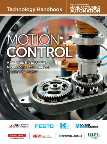
MOTION CONTROL A look into the products, technologies and solutions shaping the market
SOLVE YOUR MACHINING PROBLEMS WITH HIGH-PRECISION LINEAR SHAFT MOTORS Our Linear Shaft Motor’s patented magnetic design is extremely efficient, so it operates cooler than similar linear servos. It does not require an external heatsink, so its moving mass is smaller. Multiple form factors available to meet speciic force and space requirements!
DYNAMIC, ADVANCED CONTROLLERS Nippon Pulse provides chip, board and box-level motion controllers, so you can build a system from scratch or plug-and-play. Let us help you get started with the right electronics for your application!
n i p p o n p u l s e. co m i n fo @ n i p p o n p u l s e. co m
e l e c t ro m ate. co m s a l e s @ e l e c t ro m ate. co m
Technology Handbook | MOTION CONTROL
M
The Need for Smaller Components
oore’s Law, popularized in 1975, states that the number of transistors in a dense integrated PCB circuit doubles every two years, resulting in smaller electronics. While the rate of shrinking has declined since 2015, the demand remains for smaller and more compact technology. The motion control industry is not exempt from this trend. Many applications need to be small and portable, such as devices used in the military or medical industries. Aerospace industries are always seeking lighter solutions to reduce weight wherever they can. Robotics are becoming more complex with more moving parts in tighter spaces, and every articulated joint needs to be controlled somehow. As veteran members of the industry, ADVANCED Motion Controls® recognizes the pressing need for compact, lightweight servo drives. For this reason, we offer two standard groups of what we call “Micro-sized” servo drives. FlexPro
FlexPro™ is AMC’s newest family of digital servo drives. With cutting edge engineering, FlexPro™ is meant to deliver the capabilities of AMC’s already powerful and diverse product selection into smaller applications. The IMPACT™ (Integrated Motion Platform And Control Technology) architecture allows FlexPro™ servo drives to maintain the intelligence and power of larger-sized servo drives while fitting into much more compact packages. The FE060-25-EM is the first drive in the series with many more to come. It has the highest power density of any AMC drive to date. At just 1.5 x 1 x 0.6 inches (38 x 25 x 16 mm) in size, the footprint of the drive is approximately the same as two standard postage stamps. In other words, four of these drives can fit on a standard business card. Even with its small size, the FE06025-EM can supply brushed, brushless, stepper, and linear servo motors with up to 25 amps continuous current and 50 amps peak current. More power, network, and feedback options for FlexPro are on the way! µZ
The µZ (Micro-Z) group is a subset of AxCent servo drive family. Introduced in early 2014, the µZ drives are tiny analog 2 MANUFACTURING AUTOMATION · Technology Handbook Motion Control
PCB-mount servo amplifiers. µZ servo drives are designed to drive brushless and brushed DC motors at a high switching frequency. To increase system reliability and to reduce cabling costs, the drives are designed for direct integration into your PCB. Weighing in at just 8.5 grams, µZ Drives output 10A peak and 5A continuous and operate with a bus voltage range of 10-36VDC. Designed without the need for a heatsink, the µZ’s are true featherweights with a high power to weight ratio. The µZ’s are fully protected against over-voltage, undervoltage, over-current, over-heating, and short-circuits. Depending on the model, the drives interface with digital controllers that have analog ±10V or PWM/Direction commands. These servo drives require only a single unregulated isolated DC power supply, and are fully RoHS (Reduction of Hazardous Substances) compliant. Customs
We’re happy to develop custom micro-sized servo drives, including ones that use the same IMPACT™ architecture that makes FlexPro™ possible. Final Thoughts
Micro-sized drives are perfect for cobots (collaborative robots), AGVs, fixed robotics, mobile robotics, animatronics, portable devices, lab automation, military equipment, aerospace, medical equipment, and truly any embedded application that requires a compact and/or lightweight solution. The need for smaller servo drives is only going to increase in the coming years, and anyone who knows ADVANCED Motion Controls knows that we are always up for task. Bring it on. Written by Jackson McKay, Marketing Engineer
ADVANCED Motion Controls® 3805 Calle Tecate Camarillo, CA 93012 USA Tel: 805.389.1935 www.a-m-c.com
ELECTROMATE 6221 Highway 7, Unit #15 Vaughan, Ontario, Canada L4H 0K8 Phone: 877-SERVO98 Email: sales@electromate.com www.electromate.com
2O19
ROBOTICS BUSINESS REVIEW
RBR
50
COMPANY
Servo Drives and Motion Control Solutions for Your Industry
A u t o m a t e d S t o ra g e
ADVANCED Motion Controls® servo drives are distributed & installed worldwide; from production facilities to extreme environments; from the ocean depths to the vacuum of space; and from start-ups to multi-national companies.
Fa c t o r y F l o o r
N o w a v a i l a b l e - F l ex P r o ™ , o u r smallest, most adaptive servo drive to date! Order Fulfillment
Medical
Material Handling
Wa r e h o u s e
Harsh Environments
Ask us about standard, modified, and custom solutions to meet your exact demands.
C a m e ra C o n t r o l
D e fe n s e
Fa b r i c a t i o n
Te l e p r e s e n c e
Camarillo, CA 93012 805.389.1935 a-m-c.com
Tra n s fe r L i n e s
6221 Highway 7, Unit #15, Vaughan, Ontario, Canada L4H 0K8 • Phone: 877-SERVO98 Email: sales@electromate.com • www.electromate.com
Technology Handbook | MOTION CONTROL
Putting automation in motion faster (with less stress)!
A
s rewarding as automation is when it works as planned, designing a machine or system, selecting the right components, soliciting bids, then assembling, commissioning and debugging everything can stretch a project timeline over many months. Think of the headscratching, design do-overs, procurement snafus, parts spread out on the floor, the commissioning tedium. Motion control technology has been getting better with each new generation. Now – some would say finally – the tools for more efficient planning and prosecution of automation projects are catching up to everyone’s benefit. Festo’s new open source Automation Suite approach focuses on providing seamless connectivity to condense project timelines and reduce the cost, risks and aggravation. The bodes equally well for conventional and Industry 4.0 applications. The platform is an expanding portfolio of mechanical and electrical components, downloadable software and online configurators that are integrated and optimized to simplify and accelerate each step of a project, from planning and design through commissioning, and even beyond to component lifecycle management. Everything works well together and is compatible. For examples, Festo just introduced two next generation servo drives, the CMMT-AS for servo motors up to 2500W and pint-sized CMMT-ST for stepper motors with low power requirements up to 300W. These compact, best-in-class drives perform exceedingly well as standalone products with Festo or third party motors. Their optimal pairings are with Festo’s new EMMT-AS synchronous servo for challenging, dynamic jobs or for the
CMMT-ST, the proven EMMS-ST stepper motor. However, as an integral part of the automation suite, these drives offer additional, unique benefits: They can be commissioned in literally minutes using the new, PC-based Festo Automation Suite software, another platform innovation. With this free downloadable software, only five easy steps are needed to parameterize and configure an entire drive system using a CMMT-AS or CMMT-ST, from the mechanical system to the system controller. The software is very intuitive, with a clean looking interface that’s easy to customize. Navigation is similar to a web browser, and the commissioning wizard only retrieves settings that are really needed, which makes the software easier on new users.
See how the Festo Automation Suite makes life easier. Click here. There is a CMMT-AS plug-in for the Automation Suite to enable expert users to make advanced optimizations or integrate a CMMT-AS drive into the program of Festo’s CPX-E controller with just two clicks rather than the 100 or so it would take otherwise. There also is a plug-in for fast, easy conditioning of another new product – the CPX-AP-I remote I/O control module.
For more on the Festo Automation Suite software, click here
4 MANUFACTURING AUTOMATION · Technology Handbook Motion Control
For more about Festo’s new CMMT-AS servo drives, click here Many Festo customers have become familiar with another powerful digital planning tool – the Handling Guide Online, a configurator which enables engineers to design a Festo Cartesian handling system in as little as 20 minutes. (When the Festo Motion Control Package is ordered along with a Festo handling system, the user gets a complete optimized hardware and software package, usually in just a few weeks, all pre-wired and pre-tested to get that system up and running in no time. Cartesian motion applications can be configured and the system integrated quickly into brand name host PLCs without special programming expertise.) Besides the Handling Guide Online and Automation Suite, Festo’s growing roster of digital engineering support tools now includes Festo Projects, which simplifies project planning and the lifecycle management of Festo components and Festo Dashboards, for visualizing cloud-based data and supporting big data analytics for preventive maintenance and other advanced management processes.
For more on Festo’s electric automation portfolio, click here For more on the Handling Guilde Online and Festo Motion Control Package, click here, and here
5300 Explorer Drive Mississauga, ON. L4W 5G4 Phone: 1 877 GO FESTO festo.canada@ca.festo.com • www.festo.ca
Faster. Better. Connected. Seamless connectivity in industrial automation
Many challenges and lots of potential to become: • Faster. With design and engineering tools from Festo • Better. With the broadest product portfolio of pneumatic and electric components for maximum scalability and solutions at all levels • Connected. Smooth and seamless automation thanks to mechanical, electrical and intelligent connectivity of hardware and software from Festo
www.festo.ca Technology Handbook Motion Control · MANUFACTURING AUTOMATION 5
Technology Handbook | MOTION CONTROL
MINI ACTUATOR - INTEGRATED SERVO DRIVE
H
armonic Drive LLC, the leader in high precision motion control announces new FHA mini actuators with an integrated servo drive. This evolutionary product eliminates the need for an external drive and greatly improves wiring while retaining high-positional accuracy and torsional stiffness in a compact housing. The FHA-C Mini Series is a family of extremely compact actuators that deliver high torque with exceptional accuracy and repeatability. As part of the FHA-C Mini family, an integrated servo drive version utilizing CANopen® communication is now available. Since it communicates via CANopen, only 4 wires are needed: CANH, CANL, +24VDC, 0VDC. A single-turn 14bit (16384 cpr) gear output sensing encoder has been integrated along with a single-turn 15bit (32768 cpr) motor input sensing encoder providing a true absolute encoder that does not require a battery within 360° of rotation of the output. Our engineering team incorporated more features and capabilities without greatly impacting the size and mass of the actuator.
Key Features: • Actuator + Integrated Servo Drive utilizing CANopen communication • 24VDC Nominal +7-28VDC Supply Voltage Range • Single Cable with only 4 wires needed: CANH, CANL, +24VDC, 0VDC • Zero Backlash • Dual Absolute Encoders • Panel Mount Connectors with 4 exit options • Output Sensing Encoder 14bit (16384 cpr) resolution • Input Sensing Encoder 15bit (32768 cpr) resolution • Control Modes Including Torque, Velocity, and Position Control, CSP, CSV, CST • Harmonic Drive HDL Software The FHA-C Mini series actuators with an integrated servo drive are among the latest products developed at HDLLC in Peabody, MA.
With over 50 years of experience, our expert engineering and production teams develop enabling technologies and products to meet the needs of an evolving motion control market. We are very proud of our outstanding company history. Our high-precision, zero-backlash Harmonic Drive® gears and Harmonic Planetary® gears have, and continue to play critical roles in robotics, spaceflight applications, semiconductor manufacturing equipment, factory automation equipment, medical diagnostics and surgical robotics.
About Electromate Electromate’s Core Purpose is to help Manufacturers compete globally by building better machines using differentiated automation technology. We specialize in Robotic and Mechatronic Solutions for the Industrial Automation marketplace. Respected by customers as a premier source for High Performance Automation and Motion Control Components & Systems, Electromate® specializes in AC & DC Servo/Stepper Motors & Drives, Motion & Automation Controllers, Positioning Systems & Actuators, Feedback Devices, Gearing Products and HMI’s & Operator Displays, all supported via extensive product selection, just-in-time delivery, dedicated customer service and technical engineering support. With over 3000+ satisfied customers, Electromate® is a market leader in providing successful solutions for the Industrial Automation industry. We pride ourselves on providing our customers with Precision Technology & Quality, backed by over 100 years combined experience in technical engineering support from our responsive customer service team. Electromate is the exclusive distributor for Harmonic Drive® products in Canada, except for the province of Alberta.
Harmonic Drive and Harmonic Planetary are registered trademarks of Harmonic Drive LLC.
About Harmonic Drive LLC Harmonic Drive, LLC engineers and manufactures precision servo actuators, gearheads and gear component sets. We work closely with both Fortune 500 and companies of all sizes to understand their application requirements and provide a standard or, in most cases, a custom-engineered solution to enable the success of their design project. 6 MANUFACTURING AUTOMATION · Technology Handbook Motion Control
HARMONIC DRIVE LLC 247 Lynnfield Street, Peabody, MA 01960 Toll Free: 800-921-3332 Phone: 978-532-1800 www.HarmonicDrive.net
ELECTROMATE 6221 Highway 7, Unit #15 Vaughan, Ontario, Canada L4H 0K8 Phone: 877-SERVO98 Email: sales@electromate.com www.electromate.com
FHA-C Mini Actuator with Integrated Servo Drive
The Servo Drive is in the Actuator!
The FHA-C Mini Series is a family of extremely compact actuators that deliver high torque with exceptional accuracy and repeatability. As part of the FHA-C Mini family, an integrated servo drive version utilizing CANopen® communication is now available. This evolutionary product eliminates the need for an external drive and greatly improves wiring while retaining high-positional accuracy and torsional stiffness in a compact housing. • Actuator + Integrated Servo Drive utilizing CANopen communication • 24VDC Nominal +7-28VDC Supply Voltage Range • Single Cable with only 4 wires needed: CANH, CANL, +24VDC, 0VDC • Zero Backlash • Dual Absolute Encoders
• Panel Mount Connectors with 4 exit options • Output Sensing Encoder 14bit (16384 cpr) resolution • Input Sensing Encoder 15bit (32768 cpr) resolution • Control Modes Including Torque, Velocity, and Position Control, CSP, CSV, CST • Harmonic Drive HDL Software
Harmonic Drive LLC 247 Lynnfield Street Peabody, MA 01960 800.921.3332 www.HarmonicDrive.net
Electromate 6221 Highway 7, Unit #15 Vaughan, Ontario, Canada L4H 0K8 (877) SERVO98 (737-8698) www.electromate.com
Harmonic Drive®, Harmonic Planetary® and Quick Connect® are registered trademarks of Harmonic Drive LLC. Electromate is the exclusive Canadian distributor of Harmonic Drive® products (except the Province of Alberta).
Partners in Precision
Technology Handbook Motion Control · MANUFACTURING AUTOMATION 7
Technology Handbook | MOTION CONTROL
Hybrid Design for Hybrid Applications Lafert presents the HPS Series of permanent magnet motors for automated equipment applications where induction motor performance falls short of the mark, or servo motor cost and complexity is impractical. It’s no accident that HPS Series motors are well suited to filling this motor capability gap; the motor construction integrates the cost-effective induction motor stator housing and stator winding with high-performance permanent magnet servo motor rotor technology. The hybrid design is a highly efficient synchronous motor which outperforms induction motors and offers tremendous value for speed control applications. Lafert is an industry leader in permanent magnet motor technology and has proudly manufactured HPS Series motors for over fifteen years. HPS motors are available from stock with standard power ratings to 50 HP for 230, 460, 575 V input. Mounting options include modular base mounts with or without standardized IEC and NEMA flanges.
Reduced Losses, Increased Reliability Energy efficiency has not been a traditional performance consideration for motion control applications, but efficiency has direct reliability and performance implications for motors and systems. All HPS Series motors significantly exceed the current requirements for induction motor efficiency (NEMA Premium®) with motor efficiency performance at or above the “Super Premium” (IE4) level. The increased motor efficiency is due to the HPS Series permanent magnet rotor construction, which reduces the electrical rotor losses to zero. Induction motor rotor losses are defined as the electrical power converted to heat by current flow (I2R) in the rotor, which typically accounts for 10 – 15% of total losses. Eliminating the rotor losses delivers a dual benefit of increased energy efficiency and reduced heat generation;
HPS Series motors create less heat per unit of mechanical power delivered to the load. This explains the reduced thermal rise and thermal time constant, and the increased maximum ambient temperature and overload capability of HPS Series motors. The industry rule of thumb, which states that each 10°C rise in motor winding temperature reduces insulation life by half, establishes the case for correlation of reduced motor losses with longer field service life. With less waste heat to be eliminated from the enclosure, HPS motors require less material volume and surface area to remain cool. Space and weight savings will vary, but a reduction of approximately 50% can be expected compared to induction motors.
High Performance, Without Feedback The HPS Series construction implements a synchronous motor design, which means the shaft speed is synchronized with the rotating magnetic field developed by current in the stator windings. This contrasts against the asynchronous operation of induction motors, Rating
3 HP, 3600 rpm
7.5 HP 3600 rpm
where the shaft speed lags the rotating stator field speed by a value proportional to the motor load (the “slip”). HPS Series motors address the speed control uncertainty inherent to asynchronous motors, and can eliminate the need for costly and complex slip mitigation measures, like encoders. HPS Series motors are engineered and optimized for sensorless control by variable frequency drives, with near-universal support from drive manufacturers.
Leveraging Lineage, Learning More In addition to the benefits of synchronous operation, HPS Series motors inherit two characteristics from the servo motor with performance implications for motion applications. First, the reduced weight and dimensions of HPS Series permanent magnet rotors yield higher torque-to-inertia ratios than induction motors. Higher torqueto-inertia ratios are desirable because they support higher system dynamic response and repeatability. Second, the synchronous motor torque-producing mechanism enables the flat torque curve across a wide speed range and a shorttime 300% peak torque capability. Contact Lafert to learn how and why the unique construction and capabilities of HPS Series motors can drive top performance from your next motion control application.
CLICK HERE to download Lafert’s HPS Series Technical Catalogue.
Motor Type
Frame Size
Weight (lbs)
Inertia (10-3 lb-ft2)
Volume (ft3)
HPS
71
14.5
22
0.19
NEMA Premium® (Aluminum Body)
90
40.3
43
0.38
HPS
90
35.2
31
0.38
NEMA Premium® (Aluminum Body)
112
78.1
204
0.71
8 MANUFACTURING AUTOMATION · Technology Handbook Motion Control
Technology Handbook Motion Control · MANUFACTURING AUTOMATION 9
Technology Handbook | MOTION CONTROL
T
maxon drives set the world in motion
he maxon motor combines electric motors, gears and DC motor controls into high-precision, intelligent drive systems that can be custom-made to fit the specific needs of customer applications. maxon motor helps provide innovative solutions at competitive prices for numerous applications in various markets, such as industrial automation, medical technology, security technology, instrumentation, communications, and consumer applications, among others.
Offering solutions that fit your customized needs maxon motors manufactures small, high-quality brush and brushless DC motors ranging in size from 4 mm to 90 mm. maxon’s rhombic wound ironless rotor motors provide exceptionally high efficiency, low EMI emissions, fast acceleration, no preferred rotor position, torque constants and long service life. The drive components are assembled and designed within our modular system according to your individual needs. You can combine, according to your requirements, motors with 10 different product classes with planetary, standard or special gearheads, feedback devices, brakes and control electronics.
Brushed and brushless configurable DC motors more versions, more power
speeds of up to 120,000 rpm. They run very smoothly and are highly efficient in standard or sterilizable versions (up to 2,000 autoclave cycles). Ideal for use in hand-held surgical tools and industrial spindles. maxon motor’s X drives are extremely powerful and are now available in maxon’s online shop, where customizing the drives is easy. Customers can fit the drives with specific mechanical and electrical components specific to their application needs. It is possible to customize the shaft lengths, winding types, ball bearings and much more. When combined together with maxon encoders and planetary gearheads, you form a high-precision, robust drive system ideal for any application from aerospace to medical to robotics. In fact anywhere that requires a compact, powerful, quiet and strong drive system. The X program is a lean and automated process which ensures that all configurable drives are ready for shipment within 11 working days. In addition, detailed product data may be viewed immediately online and 3D CAD data for the configuration is available for downloading. Visit dcx.maxonmotor.com for more information.
Now even stronger, more efficient and with yet more combination options: There are new additions to the maxon family of X drive products. Several long versions of brushed DC motors, with higher torques and more power, have been added to the product range along with matching planetary gearheads. Each of the 3-stage versions can now be combined with the next smaller motor. This saves space, weight and costs. In addition, maxon launched a brushless DC motor (ECX) line to its configurable online program. These motors are available with diameters of 8, 16 and 19 mm achieving 10 MANUFACTURING AUTOMATION · Technology Handbook Motion Control
ELECTROMATE 6221 Highway 7, Unit #15 Vaughan, Ontario, Canada L4H 0K8 Phone: 877-SERVO98 Email: sales@electromate.com www.electromate.com
TRA CONFIGURABLE
Gearhead, motor and encoder tailored to your needs.
11DAYS
READY IN
Assemble your individual maxon DC drive: You can configure the gear stages, the motor bearings, the shafts, the encoder and much more. Design your custom drive online today and your finished drive will ship from Switzerland in 11 working days.
dcx.maxonmotor.com
Technology Handbook Motion Control · MANUFACTURING AUTOMATION 11
Nippon Pulse provides chip, board and box-level motion controllers, so you can build a system from scratch or plug-and-play. Let us help you Technology Handbook | MOTION CONTROL get started with the right electronics for your application!
n i p p o n p u l s e. co m i n fo @ n i p p o n p u l s e. co m
e l e c t ro m ate. co m s a l e s @ e l e c t ro m ate. co m
Linear Shaft Motor servos and electronics to solve your machining problems
D
esign engineers run up against all kinds of issues when designing a new application – ensuring the motors meet force and size requirements, making sure the electronics to run the application are welldesigned, and keeping costs down, just to name a few – and Nippon Pulse has made it our goal to help “ease the pain” of common machining concerns, with help from our patented Linear Shaft Motor and our dynamic electronics. Nippon Pulse’s Linear Shaft Motor is a brushless, high-precision direct drive linear servo motor with a tubular design. The linear actuator consists of only two parts: a magnetic shaft and coil assembly (forcer), and has a non-critical air gap, so the motor does not wear or require maintenance. The motor is driven and controlled by the flow of current.
Nippon Pulse’s Linear Shaft Motor is available with 12 different frame sizes (ranging from 4mm to 60.5mm shaft diameters) and each size has a variety of form factors depending on your space and force requirements. The motor has an acceleration force of up to 2340N and continuous force up to 585N. Nippon Pulse has the largest selection of linear motors of any manufacturer in the world! The Linear Shaft Motor can replace ball-screws, pneumatics, U-shaped motors and other linear motion systems. Nippon Pulse can also accommodate stroke lengths as short as 20mm and as long as 4.6 meters. How else can we ease your pain?
Heat and Motor Efficiency
Controller Options forMACHINING Every Application SOLVE YOUR PROBLEMS
Thought was given to every aspect of the design of the Linear Shaft Motor to make it the most efficient motor possible, and according to an independent study, the Linear Shaft Motor is 50 percent more efficient than similar coreless linear servos. Linear motors heat up due to unused energy. When heat is generated, it must go somewhere. One side effect of heat is the thermal growth of the load the coil is attached to, and the subsequent heating of the bearings, grease, and any sensors attached. Over time, the heating and cooling cycles can have negative effects on both mechanical and electronic components. Thermal growth is likely to cause issues with binding and increased friction. This is where many applications utilize heatsinks to reduce the impact of thermal growth, but heatsinks are bulky, take up extraneous space, and add mass to the application, even if the motor itself is compact and lightweight. In comparison, the Linear Shaft Motor’s ironless magnetic design utilizes all the magnetic flux, which allows us to generate force more efficiently. This greatly reduces the amount of heat generated, rendering heatsinks unnecessary. Because the heatsinks are not required, the motor can fit into smaller spaces.
In addition, by preventing wasted energy, the cost of operating the system also decreases.
Force-to-Size Ratio
Nippon Pulse manufactures a variety of options for servo control, WITH HIGH-PRECISION LINEAR SHAFT MOTORS from ultra-precise motion control with a variety of interpolation Our Linear Shaft Motor’s patented design is extremely efficient, functions, or simpler options formagnetic basic control. so it operates cooler than similar linear servos. It does not require an Among our chip, board and box controller options, you have external heatsink, so its moving mass is smaller. the flexibility to fully customize your application’s controller or Multiple form factors available to meet speciic space requirements! choose a ready-to-use solution that canforce getand you moving right away. Our goal is to impress you, not just satisfy your needs. DYNAMIC, CONTROLLERS Which option gives youADVANCED the most control? Talk to our engineers today toNippon determine the best solution for your Pulse provides chip, board and box-level application. motion controllers,
12 MANUFACTURING AUTOMATION · Technology Handbook Motion Control
so you can build a system from scratch or plug-and-play. Let us help you get started with the right electronics for your application!
n i p p o n p u l s e. co m
Nippon Pulse i n fo @ n i pAmerica, p o n p u l sInc. e. co m 4 Corporate Drive, Radford, VA 24141 Phone: 540-633-1677 info@nipponpulse.com www.nipponpulse.com
e l e c t ro m ate. co m
ELECTROMATE s a l e s @ e l e c t ro m ate. co m 6221 Highway 7, Unit #15 Vaughan, Ontario, L4H 0K8 Phone (905) 850-7447 sales@electromate.com www.electromate.com
SOLVE YOUR MACHINING PROBLEMS WITH HIGH-PRECISION LINEAR SHAFT MOTORS Our Linear Shaft Motor’s patented magnetic design is extremely efficient, so it operates cooler than similar linear servos. It does not require an external heatsink, so its moving mass is smaller. Multiple form factors available to meet speciic force and space requirements!
DYNAMIC, ADVANCED CONTROLLERS Nippon Pulse provides chip, board and box-level motion controllers, so you can build a system from scratch or plug-and-play. Let us help you get started with the right electronics for your application!
n i p p o n p u l s e. co m i n fo @ n i p p o n p u l s e. co m
e l e c t ro m ate. co m s a l e s @ e l e c t ro m ate. co m
Technology Handbook Motion Control · MANUFACTURING AUTOMATION 13
Technology Handbook | MOTION CONTROL
4 Ways to Navigate AGVs with the safePGV
N
avigating through warehouses can be a challenge for even the most advanced AGVs. So, it is important that the right guidance system is in place to ensure that material handling tasks can be performed accurately and reliably. The compact safe position guided vision (PGV) positioning system from Pepperl+Fuchs enables SIL 3/PL e-compliant safe absolute positioning of even the smallest AGVs. The PGV works with the following four guidance options: Data Matrix code tape, colored lanes, control codes, and Data Matrix tags. Data Matrix Code Tape
Data Matrix code tape is the most common means of AGV control for the safePGV. It is used for detailed and continuous absolute positioning and guidance of AGVs. The 2-D Data Matrix codes printed on the tape provide X,Y, and Z positions and 360° of angular feedback to the safePGV read head.
like light and glossy floors. Colored lanes can also be combined with code tape to enhance system availability. Control Codes
Control codes are commonly used to initiate AGV actions like starts, turns, and stops. Control codes are 1 meter in length and are installed parallel to the Data Matrix codes and colored lines. Each of the 1000 unique codes available can initiate different user-specified actions. Typically, control codes are installed directly next to Data Matrix code tape. This provides full positional information and outputs a user-specified number whenever a control code is scanned. Instead of using a specified position to initiate an action, the control codes (the number) can be programmed and installed in different places at different times. The AGV’s location can be changed or duplicated throughout the route—the number is the only constant identifier. Data Matrix Tags
Our Data Matrix code tape is self-adhesive and can track position for up to 6 miles when combined with the safePGV. The adhesive tape is easy to install, has high mechanical stability, and is resistant to high temperatures, chemicals, grease, and UV radiation. Pepperl+Fuchs also offers a clear, protective laminate adhesive cover that can be installed on top of the code tape for extra protection. Colored Lanes
While Data Matrix code tape offers more position data, colored lanes are simpler to use, cost less, and are more flexible. The safePGV is designed to track both colored tape and painted lines with widths up to 40 mm in the standard red, blue, green, and yellow. Pepperl+Fuchs software helps users quickly determine which color is best for their factory floor. Colored lines provide accurate angular feedback and Y-axis positional information, and the safePGV can track colored lines as far as they can be installed. Line readability is unaffected by background color and reflectivity because the safePGV focuses directly on the region of interest, ignoring outside influences 14 MANUFACTURING AUTOMATION · Technology Handbook Motion Control
85 x 85 mm Data Matrix tags are made up of 16 Data Matrix squares and provide all the positional information the safePGV offers.This includes X,Y, and Z positions, 360° of angular feedback, and a unique tag number. Adhesive and just as durable as code tape, the tags are easy to install and are highly resistant to chemicals, abrasions, and heat. Because of the high number of code squares in a single area, the tags offer the widest range of tolerance on the X and Y axes. This allows the safePGV to stay on track, even with rapid movement, and provides redundancy if some of the code squares become damaged or unreadable. Since the safePGV can automatically switch between tag mode and lane tracking, safePGV users can decide to use colored lanes or code tape to guide AGVs from one Data Matrix tag grid to the other.
Gerry Paci Product Manager, Advanced Positioning and Vision Systems gpaci@us.pepperl-fuchs.com
www.pepperl-fuchs.com
Leading the way. Reinventing positioning. Revolutionizing safety. SIL 3/PL e with One Sensor safePXV and safePGV Safe absolute positioning or AGV navigation with
just one sensor Direct connection to safety PLC Unique combination of 2-D camera and multi-color Data Matrix code tape www.pepperl-fuchs.com/safe-positioning
Technology Handbook Motion Control · MANUFACTURING AUTOMATION 15
Technology Handbook | MOTION CONTROL
Hollow Shaft Multi-Turn Kit Encoders for Motors, Robots
P
OSITAL’s new hollow-shaft absolute kit encoders are designed for servomotors, stepper motors, robot joints, or anywhere else their hollow center configuration can contribute to an optimal mechanical layout. Hollow shaft kit encoders are especially well suited to robots and cobots. Weighing in at just 110 g, with an outer diameter of 80 mm, these devices can be integrated directly into the joints of the robot arms. Their open-center form factor leaves room for designers to route mechanical components, cables or pneumatic/hydraulic lines through the centre of the joint. Their slim design (only 17.8 mm deep) and the large central opening (30 or 50 mm) make them ideal for other applications as well, including servomotors or drives. Like other kit (or modular) encoders, these devices are intended to be installed inside the housing of a motor or other machine, measuring rotary motions directly from the host machines drive shaft. A special feature of POSITAL’s new hollow shaft kit encoders is a multi-turn measurement range, powered by the company’s Wiegand energy harvesting technology. This eliminates the need for backup batteries and significantly reduces maintenance requirements. POSITAL hollow shaft kit encoders are cost effective and feature non-proprietary SSI and BiSS C communications interfaces.
These new products use a capacitive measurement system that delivers a high level of accuracy (+/- 0.02°) while being relatively insensitive to contamination by moisture or dust. Installation and commissioning are straightforward: a few simple steps and the measuring system is ready for use, no complex calibration procedures required.
16 MANUFACTURING AUTOMATION · Technology Handbook Motion Control
POSITAL-FRABA Inc. 1800 East State Street, Suite 148 Hamilton, NJ 08609, USA Phone: 609-750-8705 info@fraba.com www.posital.com
ELECTROMATE Inc. 6221 Highway 7, Unit #15 Vaughan, Ontario, L4H 0K8 Phone (905) 850-7447 sales@electromate.com www.electromate.com
MEET OUR NEW KIT ENCODER FAMILY!
POSITAL Takes a Fresh Look at Motor Feedback Precision motor feedback for servo and stepper motors Flexible encoder solutions for small drives, robots Incremental, absolute, singleturn and multiturn variants Fast and easy installation with factory-friendly alignment tolerances Low sensitivity to dust and moisture Good resistance to shock and vibration
www.posital.com
PREVENTING HAZARDS Motion monitoring on an external unit combines safety functions with machine efficiency BY MARCEL WÖHNER AND JÖRG FORCHT
M
otion monitoring enables efficient machine operation – but standards also demand maximum safety. With an external monitoring unit, safety functions can be implemented as standard on frequency converters and servo amplifiers of various performance classes and from various manufacturers; in most cases this can be achieved very economically. The objective of safety technology was and always will be to prevent potentially hazardous movements. Nothing, then, is more obvious than to have a close
connection between safety technology and motion generation. For technical and economic reasons, the drive electronics – servo amplifiers and frequency converters – have remained as nonsafety-related components in very many applications. In such applications, the required safety is guaranteed through additional safe components, which bring the drive to a de-energized, safe condition in the event of a fault, or safely monitor the movement of the connected motor. Motion monitoring has two main tasks: it must detect any violation of the limit values and then trigger an
18 MANUFACTURING AUTOMATION · Technology Handbook Motion Control
appropriate safe reaction. It must also detect any potential errors in the encoder system and likewise trigger an appropriate error reaction. Retrofitting safety Even with external, safe motion monitoring systems, it is possible to implement many of the safety functions that are defined in IEC 61800-5-2 by reusing the existing actuator and sensor technology, even on older drive systems. This is significant, particularly where a retrofit is involved, because it means the cost of exchanging the drive, motor and sensor technology can be saved. Existing drive functions can also continue to be used. What’s more, it is no longer necessary to undergo the sometimes-complex process of converting the existing drive program to a new system, along with the additional training required to program the safety section.
Motion monitoring has two main tasks: it must detect any violation of the limit values and then trigger an appropriate safe reaction.
The task of the external devices is to detect motion. The safety characteristic data of the employed sensors, e.g. rotary encoders or proximity switches, is significant in determining the safety level that can be achieved. Different solutions to suit the various requirements are available to monitor movements with external monitoring devices. At the highest level, it is important to distinguish between so-called standard encoders and “safe” encoders. Pre-assembled adapter cables simplify connection of the external monitoring devices. These are inserted between the drive and feedback encoder and record the motion monitoring signals. Appropriate adapters are available for all common drive manufacturers and drive models. Another advantage of using external motion monitoring modules is the fact that the safety system is independent from the employed drive system. So all the safety functions, special motion generation functions and motion control functions can be implemented within the usual system.
Compatibility with encoders An important requirement for solutions
with external safety is the ability to evaluate all standard sensor systems (rotary encoders in various designs, incremental encoders (TTL, HTL), Sin/Cos encoders) up to Performance Level (PL) d of ISO 13849-1 and two proximity switches up to PL e. This is made possible via feasibility checks within the external safety component that monitors the sensor signals. As a result, it is possible to achieve diagnostic coverage of up to 90 per cent on the encoder system. Through appropriate warning messages, a potential encoder failure can be detected early. It is also possible to use internal encoder diagnostics and to react to a potential fault signal from the rotary encoder with a protection violation. If a higher PL is required, this can be achieved by using an appropriately certified, safe rotary encoder. The important factor here is the correct interaction between encoder and safety relay. The documentation belonging to the respective encoder describes the requirements of the monitoring device, which must be met in order to use the device and to claim the certified safety-related characteristic data. If a certified, safe sensor cannot be used, it is still possible to achieve a higher PL with little effort. An additional proximity switch is fitted so that it scans the hazardous movement on a toothed wheel or shaft coupling, for example. The monitoring device can now continuously compare the established speed values from both encoder systems (standard rotary encoder and proximity switch). If the values are no longer feasible, the monitored axis is brought to a stop. As a result, motion monitoring up to PL e is possible with two standard components. Monitoring for broken shear pins or gear monitoring can also be implemented in the same way. Safe motion monitoring solutions with external monitoring devices can be used in conjunction with standard, certified Sin/Cos encoders designed for
up to PL e. As a result, safe motion monitoring can be implemented up to the maximum PL with only one encoder. If there are only a few safety functions to be linked to motion monitoring, individual relays provide an appropriate solution. Reacting to errors The more complex the task, the more beneficial existing add-on functions of the external monitoring devices are likely to be. In the event of an error, e.g. if a speed-monitoring function reacts, a drive should always be shut down as quickly as possible. Long transmission times to centralized safety systems and their program cycle times can often present a problem. With local stop outputs, which can drive the safety functions SS1 (Safe Stop 1) and STO (Safe Torque Off) directly, motionmonitoring modules can trigger a stop of the corresponding axis just a few milliseconds after the monitoring function has reacted. Thanks to integrated delay stages, it is even possible to implement the SS1 function, after an emergency stop signal has first been transmitted to the drive and after the drive’s STO function is activated when the set delay time has elapsed. This way, an axis can still be brought to a controlled standstill in the event of an error, before the controller inhibit makes braking impossible. If you need to shut down not just one but multiple drives simultaneously, a cascading function can allow you to do it simply, within a few milliseconds; this is independent of fieldbus times or task cycles on the controller. In their independence of the rest of the system, external motion monitoring systems allocate for future developments, both on the drive and the encoder side. | MA Marcel Wöhner is a product manager and Jörg Forcht is a product developer at Pilz GmbH & Co. KG. pilz.com
Technology Handbook Motion Control · MANUFACTURING AUTOMATION 19
SADZD
STANDARDIZING MACHINE DESIGN An Ontario-based manufacturing technology provider uses PC-based control to improve automation efficiencies BY SHANE NOVACEK
O
ld adages advise against reinventing the wheel, but what is a manufacturer to do when customers all want different wheels? Answering this question for global manufacturers every day is RAMP, Inc., an automation technology services provider located in Waterloo, Ontario. RAMP develops custom solutions that balance highly tailored manufacturing functionality with standardized connectivity, operation and maintainability. RAMP has tackled many large-scale
automation projects across North America and Europe in numerous industries. The company has deep application experience in many markets, with particular strength in energy recovery and automotive projects, and also has major clients in healthcare and consumer products manufacturing, electronics assembly, food production, and scientific research at various universities and institutes. With increasing domestic manufacturing activity in industrialized countries, manufacturers need more efficient production methods to improve global
20 MANUFACTURING AUTOMATION · Technology Handbook Motion Control
competitiveness. “For example, there is a strong push in domestic automotive manufacturing to increase the adoption of techniques such as lightweighting to make vehicles more fuel efficient and handle better when driving,” says Michael Balzan, director of RAMP. “The burgeoning electric vehicle market is also driving manufacturing investments and will continue to rapidly expand in the near future. We see major developments in machine autonomy, with IoT becoming more pervasive across industries.” These transformative changes push manufacturers to adopt nextgeneration manufacturing technologies, and the engineering team at RAMP can handle all the design aspects, including mechanical components, automation and controls. RAMP projects can involve the manufacturing of new products without predefined processes, and they can also modernize and replace legacy systems. To cover the entire application spectrum,
With standardized machine design, RAMP customers that have multiple divisions or facilities can move crossfunctional teams between facilities and still learn new processes quickly.
RAMP follows a structured project management development (PMD) model that stresses agile engineering. This supports concurrent project development and engineering to optimize all processes. “RAMP provides customers a significant value-add through proper and thorough engineering analyses of the end users’ products and processes,” says Jeff Kerr, manager of mechanical design at RAMP. “We start this at the outset of system implementation – even before we think about the control platform. We cross-functionally examine all requirements and break them down into individual conceptual designs. This way, we ensure that all mechanical and control components are fully compatible, resulting in the best possible solutions for customers.”
Agile engineering RAMP exudes creative engineering ideas through the company’s breadth of knowledge in diverse industries,
and the company identifies potential risks upfront. From the first customer visit, the RAMP team manages risk with proof-of-concept consultation backed by practice-proven design techniques. “A strength at RAMP is our ability to rapidly customize solutions according to each customer’s unique needs,” explains Stephen Gugeler, manager of control systems at RAMP. “We can accommodate multiple part types and rapid changeover requirements while providing standard interfaces and production methodologies. Regardless of the particular machine type or range of products they’re manufacturing, custom solutions from RAMP are designed to be inherently familiar.” With standardized machine design, RAMP customers that have multiple divisions or facilities can move crossfunctional teams between facilities and still learn new processes quickly. This
understanding spreads across engineering, technician and maintenance teams so all personnel can operate new machines and navigate changing manufacturing processes more easily. A recent RAMP client to integrate custom-built machinery is CORE Energy Recovery Solutions based in Vancouver, British Columbia. A RAMPbuilt machine installed in 2018 at CORE manufactures energy recovery ventilators (ERVs) that increase air exchanger energy efficiency in residential and commercial buildings. The ERVs are used in the CORE Mustang cross-flow exchanger line. The RAMP machine takes base materials, including a patented polymer membrane and aluminum foil, through the machine process that laminates layers of membrane and corrugated aluminum in various heights and pitches unique to each customer recipe. The
Members of the RAMP engineering team, from left: Martin Pinnau, mechanical technician; Stephen Gugeler, manager of control systems; Jeff Kerr, manager of mechanical design; and Stephen Slothouber, controls program lead. Technology Handbook Motion Control · MANUFACTURING AUTOMATION 21
In order to minimize wiring distances over to field devices, RAMP uses a machine-mounted EtherCAT Box I/O in IP 67 protection throughout the system.
second half of the machine takes the laminated materials through a high-precision vacuum conveyor designed and built by RAMP. This custom sheet layer then has separating materials placed on it using a unique pick-and-place process with common pick positions but recipedriven place positions varying from 250 mm to one metre. Finally, the layers are stacked across multiple dimensions and heights to create the last recipe-driven dimension and then exited off a conveyor to the operator. PC control software RAMP has used PC- and EtherCATbased control technology from Beckhoff Automation for over four years and has since increased its usage across the organization. “The Beckhoff control platform is the standard on three of our primary systems, including this web handling system for CORE, as well as our moulding machinery and measurement equipment used in automotive applications,” Gugeler says. TwinCAT 3 software from Beckhoff allows RAMP to handle PLC and motion control, plus I/O mapping and configuration in a single software solution. The RAMP team creates code using various IEC 61131-6 languages, ensuring that the company’s standards-based approach extends to software engineering.
TwinCAT also helps RAMP leverage open, vendor-neutral technologies like the OPC UA standard for secure connectivity to higher level databases such as Amazon Web Services (AWS) and SAP. RAMP uses a variety of TwinCAT tools for high-speed data analysis and advanced code development. “TwinCAT 3 excels in all areas of PLC and motion control programming, but goes far beyond this,” Gugeler says. “For example, ScopeView makes troubleshooting and modification efforts faster and more efficient. And since the platform directly integrates with Microsoft Visual Studio, RAMP can take advantage of standard computer science tools and methods, such as C# for UI development. This means we can fully leverage emerging engineering talent from local universities and colleges. These new engineers entering the workforce are very familiar with IDEs like Visual Studio, but may not have interacted with a traditional PLC before.” Industrial PCs Based on the application requirements and specifications from CORE Energy Recovery Solutions, RAMP required a high-powered industrial PC (IPC) to handle all automation software and Windows applications, as well as the company’s recipe and data acquisition
22 MANUFACTURING AUTOMATION · Technology Handbook Motion Control
solutions. “We needed an IPC that could run our applications at a one millisecond update rate to provide maximum control over the process. That led us to the high-power, cabinet-mounted C6930 IPC from Beckhoff,” says Steve Slothouber, project control lead at RAMP. The C6930 that RAMP selected features a fourth-generation Intel Core i5 processor (two cores, 2.7 GHz). RAMP connects the C6930 IPCs to CP2916 multi-touch control panels to display dashboards that run on an HMI server for local and web-based access. The dashboards are filled with overall equipment efficiency (OEE) information and important data from existing validation systems. RAMP uses two CP2916 panels with 15.6-inch displays for HMI hardware, allowing for easy operation and process control. To cover I/O requirements, RAMP standardized on an EtherCAT system that offers analog and digital devices rated in IP 20 and IP 67 for all data acquisition and machine safety requirements. The IP 20 EtherCAT terminals result in a smaller enclosure footprint and permit a free mix of safe and nonsafe I/O in the same segment. Highdensity (HD) EtherCAT terminals, which offer as many as 16 I/O channels in a 12-mm wide terminal housing, promote space savings. These also greatly
reduce wiring effort through DIN rail installation and cage clamp wiring connections. “The EtherCAT I/O system provided the high-speed networking and fast scan times we needed while ensuring flexible network topologies,” says Matt Buchwald, electrical design lead for RAMP. “The CORE application requires high-end control technology that can react to production changes and adjust output controls in under 10 milliseconds.” The application also had to integrate with various third-party field devices on different networks, and each protocol had to be managed in the central controller. In this case, the EtherCAT I/O system directly connects to EtherNet/IP hardware required on the machine. This included devices installed on web handling equipment, vision system hardware, automatic power tensioning controls and dispensing units. In order to minimize wiring distances to field devices, RAMP uses machinemounted EtherCAT Box I/O in IP 67 protection throughout the system. “This allows us to place our field inputs and outputs closer to the application and reduce overall cable length and cable track requirements,” says Buchwald. “Integrating all safety systems on the same EtherCAT network via TwinSAFE I/O further reduces overall cabling and electrical assembly time. The safe inputs and outputs efficiently connect with safety doors, light curtains, area scanners and e-stops. TwinSAFE also handles Safe
“Even before we think about the control platform, we cross-functionally examine all requirements and break them down into individual conceptual designs. This way, we ensure that all mechanical and control components are fully compatible.” Torque Off (STO) functionality on some hard-wired motion control equipment.” For drive technology that would reduce cabinet space, RAMP applied 24-mm wide EL7211 servomotor terminals for some of the machine’s motion control requirements. “We can use one low-cost 48-volt power supply for the EL7211 drives, significantly reducing space and cost requirements for servo drives,” says Gugeler. Beckhoff stepper technology also factors into the application, with AS1020 stepper motors used for low-cost control of motion, velocity and position. These are driven by EP7041 stepper motor modules rated at 50 V DC, 5 A, with built-in incremental encoder for resonance-critical applications. For higher power and load requirements, the RAMP machines also incorporate AX5000 series digital compact servo drives for high-end position control, electronic gearing, velocity control and super-imposed position control. The drives connect to AM8000 series servomotors, which
The drives used in RAMP’s soluctions connect to Beckhoff Automation’s AM8000 series servomotors to handle conveyance, pick and place, web lamination, tension control and height adjustments for the production line.
cut up to 50 per cent of motor cabling and connectors, to handle conveyance, pick and place, web lamination, tension control and height adjustments for the production line. Lowering costs As the machine control system for CORE Energy Recovery Solutions evolved over a year of development, RAMP repeatedly added new field devices for data acquisition. “We were initially concerned about over-taxing the IPC from a data-processing perspective, but the system capably handled continual increases in data, even while handling all automation and control functionality,” says Balzan. “The stakes were high in this tight deadline project, because if the CPU and RAM couldn’t keep up, it would have required a major redesign.” Since RAMP first transitioned to PCbased control and EtherCAT technology, the company has had ample time to compare metrics with older generation PLC- and PAC-based systems. “We clearly increased control quality, improved system reliability, increased productivity and boosted OEE for all RAMP solutions with PC-based control,” says Gugeler. “Specifically, we improved PLC cycle times by 30 per cent and reduced control system costs by approximately 30 per cent.” With the results apparent in the company’s engineering approach to networking technology, RAMP continues to use PC-based control to create fully customized machines with the efficiency found in standard, series production machines. | MA Shane Novacek is the marketing communications manager for North America at Beckhoff Automation. beckhoff.ca
Technology Handbook Motion Control · MANUFACTURING AUTOMATION 23
BREWING A BETTER BEER A new process automation system at Sleeman Breweries provides internal process and recipe control BY GREG HOOD
T
en years ago, tourists looking for a taste of the local life in Southern Canada may have asked for one of the region’s best wines. Today, it’s all about craft beer. From entrepreneurial newcomers to large-scale producers, brewers in
Canada are cashing in on the thirst for craft beer. The number of microbreweries – producing less than 25,000 cases of 24 – has more than doubled in the last seven years. The explosion in craft beer popularity had one company – Sleeman Breweries – bursting at its production seams. The third-largest brewer in Canada, Sleeman brews and distributes popular beers from lagers to pale ales. With a notorious past in bootlegging and a brewing history dating back to 1834, the company has re-emerged as a powerful presence in the craft beer market. Sleeman operates three brewing production facilities located in Ontario, Quebec and British Columbia.
Modernizing craft brewing An increase in craft beer demand is ideal for a company like Sleeman, but running out of production capacity is not. At its Okanagan Spring Brewery
24 MANUFACTURING AUTOMATION · Technology Handbook Motion Control
(OSB) in Vernon, British Columbia, the company was struggling to meet market demand for its OSB beers. The management team was looking for ways to increase output beyond the maximum of eight brews per day. If unable to increase production capacity at OSB, the company could be faced with the need to build a new facility at a high capital investment cost. At the time, Sleeman had engaged third parties to produce enough to meet customer demand – not ideal for managing costs, ensuring consistent quality and flavour, and meeting delivery deadlines. Not only was the facility limited in its ability to increase production, the existing infrastructure was based on an antiquated, semi-automated control system. Changes to the brewing process – including adding new recipes – needed to be made manually, which increased the risk of human error or inconsistencies. Throughout the
Batch reporting was ad hoc and required operators to input numbers on paper, limiting real-time access to critical information such as pressure and flow rates. approach based on the PlantPAx distributed control system (DCS) from Rockwell Automation and McRae’s own Meridian BrewSoft and BrewSight software. The system includes reporting and historian software that collects, tracks and records key process data to pinpoint brew cycle trends, allowing operators to proactively make changes to brews as needed. A library of process objects provides predefined controller code and faceplates, and the new system helps Sleeman operators more quickly configure new batches and build recipes. McRae customized the solution for brewing applications with its software solutions, which provide operators with Better control for control of the process through web inbetter brews The Sleeman team worked with Mc- terfaces. Allen-Bradley PowerFlex 525 Rae Integration, a system integrator and PowerFlex 755 drives deliver motor for Rockwell Automation, to design control in the brewing process and help and implement an integrated process communicate device diagnostics to the automation system to increase capacity, control system. To complete the implementation, reduce risk and provide access to realMcRae worked with Sleeman’s IT time production data. The Sleeman team was hoping to team to install VMware virtualized servers. The Sleeman team standardize on one solution had implemented redundant across its facilities. A single servers at its Vernon facility platform would enable execua few years earlier, but found tives to view production metthe costs of the equipment rics and operations data for all 50% and additional storage space facilities from the corporate difficult to maintain. The location. With one common VMware virtualized servers platform, in-house mechanics and electricians also could Within two weeks of provided automatic redundancy for production data more easily transition from implementing the new process one facility to another and automation system, with better data recovery and expanded data storage. keep parts storage stream- Sleeman increased its beer production One virtualized server can lined. by 50 per cent. replace up to four physical “A single platform would backup servers, helping to give us insights across the line and between facilities, so we could offset the equipment hardware costs. build on successes and meet our goals It also provides the Sleeman team for continuous improvement while with the ability to create copies of the continuing to make great beer,” says virtualized servers to run simulations offline and test production changes Stefan Tobler, brewmaster at OSB. McRae implemented a phased before they are made. production process, operators needed to be at the right place at the right time. If the operator was not on the line to move production forward, brewing would be on hold. These constraints limited Sleeman’s ability to respond quickly to changes in consumer taste or trends in the industry. The manual approach also hampered access to accurate and timely production metrics needed to fully control the brewing process. Batch reporting was ad hoc and required operators to input numbers on paper, limiting real-time access to critical information such as pressure and flow rates.
Ready for more beer Within two weeks of the implementation, Sleeman increased production by 50 per cent at its Vernon facility, going from eight brews to 12 brews per day. The brewing team can now complete all brews on-site without using third-party producers. And they have avoided the cost of a new facility or significant equipment upgrades or additions. Additionally, operators have gained more control over the brewing process. With web browser–based recipes, operators can more easily build a new recipe, create a test batch, and store the recipe in the system for additional testing and production. Brewing managers can make process and recipe changes via a web browser interface, without additional personnel. Management can check on any production issues leveraging the PlantPAx system’s trending capabilities and the BrewSight software’s reporting. With exception reporting, the system creates reports to track progress as the brews reach fermentation and emails management if any brew variables deviate. The brewing team can take any corrective action needed and reduce downtime, rather than reworking and blending off the brew in small amounts later. “Craft brewing involves a lot of small changes in recipes – based on water, incoming malt and other variables – plus adding new recipes,” says Tobler. The software upgrades have kept the brew quality high while increasing production speed. The Vernon facility now has a two-hour brew cycle, with improved consistency in flavour and quality. The Sleeman team is not done – they plan to implement the PlantPAx platform throughout the rest of the Vernon facility, including the tank farm and packaging lines. As the standardization across all areas of Sleeman’s facilities expands, corporate visibility will improve, allowing the company to more effectively make decisions that will grow their business. | MA Greg Hood has worked at Rockwell Automation for more than 20 years, and is currently the solutions and applications business development manager. rockwellautomation.com
Technology Handbook Motion Control · MANUFACTURING AUTOMATION 25
DON’T MISS OUT on your next issue of
IT’S FAST, IT’S EASY AND IT’S FREE! SOFTWARE: Why small business environments cannot follow the enterprise approach. p.24
CYBERSECURITY: Keeping plant floor secure in ADVANCED WARNINGS: your the Industrial Internet of How the connected industry can help you predict and prevent failures. p.20
TECHNOLOGY: Cloud and Fog computing will advance SCADA systems. p.22
INDUSTRY WATCH: Making sense of Big Data, IIoT and Industry 4.0. p.10
BACKSTORY: Boost your business by expanding into international markets. p.30
Things era. p.12
Your resource for Canada’s industrial automation news
AutomationMag.com
50 years of
Glad
PM 40065710
PM 40065710
Ontario plant celebrates milestone anniversary p.18
NOVEMBER/DECEMBER 2017
MARCH/APRIL 2017
DOMESTIC INVESTMENT Ontario manufacturer purchases a new vertical machining centre, slashing lead time and internal costs. p.16
MAY17 AC Branding Front Cover Banner (MA).qxp_Layout 1 4/20/17 3:32 PM Page 1
Automation, electromechanical, cabling, and interconnect products from 300+ manufacturers.
thinkallied.com thinkallied.com MA_AlliedBanner_May.indd 1
MA_mar_Apr_ 2017.indd 1 MA_AlliedCover_JanFeb .indd 1
2017-04-21 11:48 AM
2017-03-01 9:51 AM 2016-12-21 9:16 AM
HERE’S HOW: FOR FASTEST SERVICE VISIT
AutomationMag.com AND CLICK THE SUBSCRIPTION BUTTON
AutomationMag.com