Digital supplement to
Technology Handbook
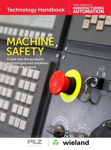
MACHINE SAFETY A look into the products, technologies and solutions shaping the market
PHOTO: GENKUR / ISTOCK / GETTY IMAGES PLUS / GETTY IMAGES
Technology Handbook | MACHINE SAFETY
IO-Link Safety: Transforming the Future of safety communication and diagnostics.
W
ith manufacturing companies moving into industry 4.0, data generated on the plant floor is increasing in importance. IO-Link has been a great success in reducing installation cost, providing greater flexibility and increased data to the user while keeping the communication universal. The machine safety market has many of the same needs as the standard machine control. The systems need easier installation, which includes wiring simplification and simplification of product configuration. Installers are also looking to have fewer components to stock while still having the flexibility to use the best product for the application. Direct device to controller wiring is currently the most common architecture. While this architecture is well known and universal it does lead to increased wiring cost and decreased immunity to noise and wiring faults. Since IO-Link was such a great success IO-Link safety is a natural progression to the technology. The IO-Link safety standard is defined in the IEC 61139-2 standard and can meet Ple or Sil 3 according to EN ISO 13849-1 and IEC 61508/62061 standards respectively. IO-Link safety acts as an extension of the existing safety networks like Profisafe and enables communication down to the safety component unlocking the path of data held in the component. Just like the existing IO-Link communication, IOLink safe communication comprises of 3 main parts apart from the safety PLC: 1. The IO-Link safety master; the gateway between the higher-level network (ex. Profisafe, CIP safety, FSoE etc.) and the IO-Link safety device. 2. The Cable; typically, an unshielded m12 3 wire cable with a length of up to 20m. 3. The Safety component ex: Light curtain, Area scanner, door interlock etc. The safe communication remains noise resistant due to its 24v signal level. It can carry up to 32bytes of data bidi-
rectionally at up to 230,4kbit/s, allowing safety, diagnostics, configuration, and additional features to be transferred. In addition to IO-Link safety communication many devices will also be able to function in OSSDe (standard dual channel safety signal) mode when the configuration of the device is needed but an io link master is not in the system. What makes IO-Link safety communication safe is the addition of the Black channel principle already in use in existing safety networks and the addition of safety measures in the communication that include: • Message numbering • Time expectation via a watchdog timer • Device authentication on startup • CRC (Cyclic redundancy Check). By using the standard M12 connection a typical safety device that used to have up to 12 wires which could take over 1 hour to wire in traditional ways can now be connected in less than a minute. The connection is less prone to wiring errors and since IO-Link safety provides identification data a device connected in the incorrect port can be detected and corrected immediately. The IO-Link safety masters are even downward compatible with standard IO-Link devices making your system even more universal.
2 MANUFACTURING AUTOMATION · Technology Handbook Machine Safety
Pilz will be introducing in the first half of 2024 its first IO-Link safety devices. The Profisafe IO-Link safety master will include 4x IO-Link master ports compatible for both standard and Safe IOLink devices and 4 Traditional safety IO ports allowing you to take advantage of the new components but also supporting exiting safety components on the market. The next generation of the advanced light curtain PSENopt II Advanced will take advantage of IO-Link for configuration for applications where Blanking, Muting etc. are required and additional diagnostics will be provided like single beam evaluation. The future PITgatebox with IO-Link Safety will also help reduce cost and provide more flexibility and reduced cabling complexity by allowing up to 15 Pilz SDD (Safety Device Diagnostics) enabled safety components to be daisy chained to the IO-Link PITgatebox allowing 16 safety devices to be connected a single IO-Link Safety port. Keep an eye out for all the innovations that will be introduced in the coming year to make your plant smarter and safer. Written by: Guillaume Lavoie, CMSE® Product Manager at Pilz Automation Safety Canada L.P. www.pilz.ca
We make Canada safer. A little bit every day. ™
Safely. Find out more: www.pilz.com/we-automate-safely Pilz Automation Safety Canada L.P. - Mississauga, ON Website: www.pilz.ca Email: info@pilz.ca Phone: +1 905 821-7459
Technology Handbook | MACHINE SAFETY
Your Ultimate Q&A on Power Bus Systems Are there any disadvantages or challenges associated with decentralized power systems?
What is a decentralized power bus system?
A decentralized power bus system typically refers to an electrical power distribution system that is designed to manage electrical power in a decentralized or distributed manner over multiple points. In a decentralized power bus system, the power distribution is streamlined, and power is supplied closer to the point of use.
A typical centralized power system
How does a decentralized power bus system differ from a centralized one?
In traditional power distribution systems, power is often centralized and transmitted over long distances from power supply cabinets to various machines or motor drives. Decentralized power distribution significantly simplifies the power pathway by reducing the physical distance between a piece of equipment and its power source.
What are the key components of a decentralized power bus system?
Two key components of a decentralized power distribution system are a multiwire main power bus cable and tap-off modules. The Tap off modules are designed to connect and draw power from the bus cable to individual devices, such as motors on a conveyor line. Depending on the system and application scenario, the incoming power could come by one of the taps or through an incomer box.
What advantages does a decentralized power bus system offer? A decentralized power bus systems offers multiple advantages to modern factories. Firstly, it significantly simplifies the design and fabrication of power infrastructure within factories and warehouses that use large conveying systems or machine
A Decentralized system using podis
Some decentralized systems use an insulation piercing technology (IPT) which can be destructive to the copper conductor of the main power cable, resulting in voltage drop and deterioration of the system over time. However, newer technologies such as the podis® power bus use a non-damaging copper displacement technology which prolongs the system’s performance and lifespan.
What applications are best suited for decentralized power bus systems?
Applications such as large conveyor systems used in airport baggage handling or warehouse automation are perfect applications for decentralized power bus systems. In addition, automated machining centers and material handling equipment also work well with decentralized power. Components of the podis power bus Copper Displacement
cells. Significant cost reductions are achieved by minimizing complex wiring and associated electrical conduit throughout the factory or warehouse.
A decentralized power distribution system using a power bus also adds flexibility to power infrastructure by allowing motors and machinery to be connected and disconnected anywhere along the bus quickly and easily. This allows factories to effortlessly and rapidly adapt by shortening commission time. Lastly, and unique to the podis® system, is the considerably accelerated installation time. The unique taps take only minutes to install, saving valuable time during deployment and subsequent changes.
4 MANUFACTURING AUTOMATION · Technology Handbook Machine Safety
How are faults managed in a decentralized power bus system?
Managing faults in a decentralized power bus system involves a combination of protective measures, monitoring, and control strategies to ensure the reliability and safety of the system. Integrated circuit breakers or fuses, current monitoring sensors at the start of a power bus or temperature sensors placed on equipment or motors may all be integrated into a decentralized bus system.
What standards exist for decentralized power bus systems?
In the US, standards such as UL 2875 (Signal and Power Distribution for Industrial Control) and UL 1277 (Standard for Electrical Power and Control Tray Cables) dictate the use of power bus distribution systems.
The Typical Pipe And Wire Installation... - Miles of metal conduit and junctions stuffed with wire
Revolutionize Your P o w e r Di s t r i b u t i o n
0
WASTE
88%
FASTER
100% POWER
- Messy wiring - Time-consuming installation - Complicated system architecture - Changes require system-wide shutdowns and extensive cable changes - Time-consuming fault locating - Material waste
The podis® 5G16 cable provides up to 60 A. + Taps are installed and moved freely without the need for major system or cable changes + Insulation piercing tech with 100% connection guarantee requires no stripping + Faster installations & changes + Faster fault-finding and increaased uptime + Reusable components + Zero waste!
LEARN MORE www.wieland-a americas.com
SAFETY STANDARDS
A3’s new safety standard for industrial mobile robots specifies safety requirements that systems integrators should implement when deploying the robotics systems. BY SUKANYA RAY GHOSH
6 MANUFACTURING AUTOMATION · Technology Handbook Machine Safety
R
obotics in automation for manufacturing facilities has evolved significantly over the years. There has been a notable shift towards greater humanmachine collaboration, especially with the increase in applications for different types of collaborative applications. Another type of robot deployed on factory floors and warehouses today is the autonomous mobile robot (AMR) or industrial mobile robot (IMR). Typically used for material handling applications, IMRs often operate in
PHOTO: IMAGINIMA / E+ / GETTY IMAGES
MOBILE ROBOT SAFETY 2.0: SAFE INTEGRATION GUIDELINES
specifies requirements for integrating, configuring and customizing an IMR or fleet of IMRs into a site, according to a press statement announcing the publication of the standard. The new standard is accredited by the American National Standard Institute (ANSI). “With the rapid development of mobile robot capabilities, it’s more important than ever for the safety of human workers to have common safety requirements and expectations for IMR systems and system integrations,” said Carole Franklin, director of robotic standards development at A3, in the statement. “The R15.08 Part 2 is muchneeded guidance toward ensuring safe integration practices for IMRs and will be a solid foundation for future work in this area.” This recent document, ANSI/A3 R15.08-2: • Describes different types of IMRs and aspects of IMR systems • Covers the adaptations necessary for the application and the facility in which the IMR(s) will be used • Describes safety requirements when IMRs interact with workstations, charging stations, and other equipment • Explains safety considerations regarding the deployed operating environment
dynamic environments alongside human workers and other machinery. Safety is, therefore, of paramount concern when implementing them in a factory setup. For several years now, the Association for Advancing Automation’s (A3) Robotics Standards Development Committee has been working on an ANSI standard for mobile robot safety. ANSI/RIA R15.08-1, a type-C standard, debuted in 2020 and features technical requirements for the design and manufacture of industrial mobile robots.
Taking the safety standard a step further, in October this year, A3 published the second installment of its safety standard for industrial mobile robots (IMR) – ANSI/A3 R15.08-2. The standard provides guidance on safe integration practices for these systems. The document R15.08-2, the American National Standard for Industrial Mobile Robots (IMRs) – Safety Requirements – Part 2: Requirements for IMR system(s) and IMR application(s) provides safety requirements for deploying IMRs into an industrial environment. R15.08-2
“A paradigm shift has occurred in recent years with the continued advancement of mobile robots in the workplace, and this shift demanded safety requirements beyond what is offered in other robot safety standards,” noted Franklin in the press statement. “With Part 2 of the R15.08 standard, system integrators now have specific requirements that will help them ensure they’re deploying the safest mobile robot systems available in their customers’ facilities.” The need for a safety standard In an interview with Manufacturing AUTOMATION, Carole Franklin discussed the need for the safety standard and the objective behind releasing the guidelines for systems integrators.
Technology Handbook Machine Safety · MANUFACTURING AUTOMATION 7
The R15.08 family of standards is intended for safety requirements for mobile robots in the industrial setting. Franklin shared that this standard follows the structure of A3’s first standard for industrial robots – ANSI/RIA R15.06 – is a national adoption of ISO 10218. “The new part [R15.08-2] is setting safety requirements for the system integration of a system of those machines into the user’s facility. So, the intended user for Part 1 is the manufacturer of the robots, the IMRs. And for Part 2, the intended user is whoever is doing the integration or what in our industry, we call integrators. Right now, we’re working on a Part 3, which will give safety requirements to the ultimate user of the system of machines so that they can continue using and operating them safely throughout the lifecycle of the machine. We’re in the fairly early stages of drafting part three. We’re trying to follow a structure that our committee members and hopefully users of the standards if they are coming to it from the R15.06 world, will find familiar,” explained Franklin. Conventional industrial robots are fixed in place and have different safety implications from IMRs. They are contained in a safeguarded space where they are either enclosed physically or have sensor-based guarding that
protects people from approaching too closely, while the robot is working in an automatic mode. Collaborative applications are built for human-machine collaboration where people are able to work alongside them with proper safety precautions and training in place. Since these robots are also fixed in place, people are expected to treat the area where they function as a hazard zone, explained Franklin. People approaching them to perform tasks in collaboration with the robot should be trained to be aware of this, she added. “In the mobile [robot] world, you could have a worker in a warehouse who has no intention of interacting with the robot at all, has no task related to the robot, and is completely unaware of the robot. Nevertheless, the robot can approach them. When the robot can now move around the facility, it brings its hazards with it as it moves. It’s very important to have the robots be capable of detecting the human and avoiding them so that you know that there is collision avoidance,” shared Franklin. Collision avoidance is very dependent on the navigation system of the machine. “Currently, my understanding is that the collision avoidance or navigation systems out there today, cannot be certified
8 MANUFACTURING AUTOMATION · Technology Handbook Machine Safety
as having a safety function at a performance level greater than B. Depending on the hazard presented, you might want a performance level greater than that. You might want a performance level C or D. The current edition of the R15.06 says there has to be Category 3 PLd safety level. So, the difficulty is that the sensing and navigation technologies aren’t there yet for mobile robots to be certified for collision avoidance at that level,” noted Franklin. She added that it is therefore very important that the IMR system be carefully planned out. IMRs are generally added to existing facilities as opposed to spaces that are purpose-built for them. So, it is important to assess the deployed operating environment and make sure that it is set up for the robots to operate safely. “Each robot system is so unique, that assessing its risks and hazards is not only important but also in some cases, very challenging. It’s very challenging, but it’s also important to do a thorough risk assessment. It’s not just the size and the weight and the speed involved. It also depends on what other equipment is on the robot. So, whether it’s got something hazardous in its grippers, or if it’s got a payload that could slosh. So, you can’t just say that the smaller lighter robots are ‘safe.’ You have to consider the whole system,” shared Franklin.
PHOTO: ICHIGORIDER / E+ / GETTY IMAGES
SAFETY STANDARDS
Safe IMR deployments With a guideline now available for implementing IMRs, where do safety considerations come in when adding mobile robot systems? Safety should be a part of the process right from the very beginning, said Franklin. A preliminary risk assessment should be part of the quoting of the project and the initial vendor selection. It has to be designed in from the start and planned for. Franklin explained that it cannot be a situation where the entire system is designed and then safety guidelines are added in. Franklin shared the primary focus points in the newly published safety document for systems integrators. “Number one, do your risk assessment. Like with our R15.06 risk assessment is a requirement to say that you’re in compliance with our R15.08 standard. The more familiar you get with the concept of risk assessment, the more you realize it’s actually iterative. It’s not a single step in the process. It’s a whole process. And you have to keep doing it over and over again throughout the whole design process for the robot system,” she said. Number two, she noted, is that systems integrators have to consider the entire facility where these mobile robots are being deployed with the same amount of care that would be applied when adding a robot cell with a fixed-in-place robot. “The amount of care that goes into designing a robot cell and controlling every aspect of it, from the dimensions to the machinery that’s in there, to how people access it - that’s a great deal of care put into designing the robot cell for a variety of reasons, safety being clearly an important one. You have to put that same amount of care into designing the entire workspace now where these mobile robots are going to be operating,” she noted. Franklin explained that in a metaphorical sense, the whole facility where they can operate is like their robot cell. A human could be exposed to their hazards in that entire space. “You have to consider the entire deployed operating environment and you also have to compare it back to what the
“It’s very important to have the robots be capable of detecting the human and avoiding them so that you know that there is collision avoidance,” says Carole Franklin of A3. manufacturer specified as the operating environment. This point is related to the second point, but you can consider it a third point of its own. If you’re undertaking an act of integration of these robots, you have to be sure you’re familiar with the information that the manufacturer of the robots has provided. One of the things that an integrator should do is compare the manufacturer-specified operating environment to the deployed operating environment and see if there are any mismatches. If there are mismatches, it’s not necessarily a showstopper, but you have to figure out what are the hazards arising from those mismatches, and how can we mitigate them. So, for example, if the manufacturer says the robot is stable if it’s operating under a certain degree of inclination and as an integrator, you go to your proposed site and realize they have some ramps that are at a greater degree of inclination than that, you know that wouldn’t be safe to operate those IMRs,” noted Franklin. She added that the integrator would have to figure out a suitable solution, such as preventing robots from accessing the ramps or building in some kind of add-on ramp that makes the ramp longer but also shallower, or so on. “With every robot system, they’re so unique that it all comes back to the risk assessment for your particular unique system, identifying what those hazards are and coming up with plans to mitigate them,” shared Franklin. Franklin explained that systems integrators are the actual crucial connection points in ensuring safety for both fixed-in-place and mobile robots. They are the bridge between the manufacturer of the IMRs and the IMRs system, and the ultimate user of the IMRs. It is absolutely crucial that there’s a flow
of information. Relevant information from the manufacturer flows through the integrator to the ultimate end user. Franklin noted that they play a very crucial role and need to be familiar with all safety standards of the machines they are integrating. She further explained that all safety standards are reviewed and updated every five years or sooner if there is a need for it due to constantly evolving technologies. It is, therefore, necessary for all stakeholders to be retrained on the updated versions to remain compliant with the safety standards. Each safety standard is part of an ecosystem of interrelated standards that have to be considered in reference to one another. Franklin explained that in order to apply each safety standard correctly, all stakeholders, including manufacturers, systems integrators and the end users, need to understand the reference standards as well. “A lot of the foundational safety concepts in machinery safety are consistent. We are using many of the same reference standards in our R15.08 as we do in our R15.06. So, you also have to pay attention not just to when one standard is updated, but also when updates to those reference standards get made,” she noted. She added that at the International Robot Safety Conference (IRSC) which is conducted annually, A3 discusses all the updates and changes that have taken place in safety standards in the past year. It is a good place to keep track of important standards. The use of technology and the adoption of robotics is an improvement on safety as it takes humans away from performing hazardous tasks, said Franklin. The safety space is quite conservative because it relates to people’s lives. New technologies have to prove themselves as being at least as good as what they’re replacing. The R15.08 committee is considering developing technical reports to address emerging topics such as mobile robot technology advances. Such topics will likely include multi-sensor fusion, additional stability testing, stability validation and additional dynamic stability testing. | MA
Technology Handbook Machine Safety · MANUFACTURING AUTOMATION 9
TAKING THE REINS: Women in leadership roles inspiring change. p. 12 IS CANADA READY FOR AIOT?: AIoT promises to bring the power of AI to operational technology. p. 12
CASE STUDY:
Automated welding system increases speed of production using EtherCAT and PC-based control. p. 14
CONNECTED SOLUTIONS How the latest technologies are solving critical problems in manufacturing. p. 14
CASE STUDY: Honda’s retooling strategy for future-proof facilities. p. 16
TECHNOLOGY: Top five trends in motion control for 2023 p. 14
CASE STUDY:
Improving performance specs on custom machines with vendor support. p. 16
CYBERSECURITY: Building secure connected factories of the future p. 18
CATCHING UP WITH INDUSTRY 4.0: Canadian manufacturers lag in technology adoption p. 8
THE BIG PICTURE: An overview of Canada’s participation at Hannover Messe 2023. p. 22
FAR-SIGHTED VISION: Artificial intelligence will allow machine vision implementaion in a growing capacity. p. 16
THE BIG PICTURE Notes from the field: Trends in artificial intelligence shaping the industry today p. 24
Your resource for Canada’s industrial automation news
Your resource for Canada’s industrial automation news
SYSTEMS INTEGRATOR OF THE YEAR
Your resource for Canada’s industrial automation news
Your resource for Canada’s industrial automation news
Systematix offers solid support to client Leggett & Platt Lakeshore throughout its automation journeys and beyond. p.10
TOP 10
UNDER 40 Joshua Pickard from Eigen Innovations shares what motivates him to work in this industry. p.6
COBOTS
LEND A HAND
TOP TRENDS IN 2023
A heavy equipment maker adds cobots to its high-mix low-volume manufacturing environment. p.10
Automation technologies and solutions to consider this year p.8
FLIP FOR
OFFICIAL SHOW GUIDE 2022
2022 SHOW GUIDE OFFICIAL him to work in this industry. p.6 Innovations shares what motivates Joshua Pickard from Eigen
environment. p.10 high-mix low-volume manufacturing A heavy equipment maker adds cobots to its
UNDER 40
TOP 10
FLIP FOR
LEND A HAND
COBOTS
Your resource for Canada’s industrial automation news Your resource for Canada’s industrial automation news
technology. p. 12 power of AI to operational AIoT promises to bring the IS CANADA READY FOR AIOT?:
control. p. 14 of production using EtherCAT and PC-based Automated welding system increases speed
CASE STUDY:
Messe 2023. p. 22 participation at Hannover An overview of Canada’s THE BIG PICTURE:
in technology adoption p. 8 Canadian manufacturers lag INDUSTRY 4.0: CATCHING UP WITH
implementaion in a growing capacity. p. 16 Artificial intelligence will allow machine vision
FAR-SIGHTED VISION:
the industry today p. 24 artificial intelligence shaping Notes from the field: Trends in THE BIG PICTURE
Canada’s #1 Resource for Industrial Automation Leaders & Decision Makers
SUBSCRIBE NOW
automationmag.com