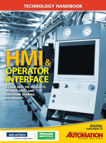
TECHNOLOGY HANDBOOK
HMI & OPERATOR INTERFACE
A LOOK INTO THE PRODUCTS, TECHNOLOGIES AND SOLUTIONS SHAPING THE MARKET
DIGITAL
SUPPLEMENT TO
MACHINE DESIGN • SYSTEMS • TECHNOLOGY
TECHNOLOGY HANDBOOK
HMI & Operator Interface
Smart Operator Panels
T
he evolution of operator interfaces has moved quite far beyond the push button technology. Once, the intelligence resided in the operator’s brain and considerable experience and training were required to operate any complex piece of machinery or process. The evolution of the operator panel is actually two parallel tracks. First is the movement of that intelligence from the operator’s brain into the operator panel itself. So, we now refer to them as “smart operator panels”. The other track is how the evolution of the operator panel tracks Moore’s Law, making them incredibly more powerful and less expensive over and over. Smart operator panels permit the operator to have access to large amounts of information in one location, on one or just a few screens. This may include process data, quality data, performance of the cell, unit or batch, as well as controls for the system themselves. What is a Smart Operator Panel? It’s a computer – an embedded computer complete with input/output, memory, a processor, and a display in an enclosure that is suitable to the environment the panel will be used in, from rack mount to enclosures that are waterproof or explosive proof. It serves many functions formerly handled by multiple devices. It is a control panel, with push-button analogs and displays. It can be used as a data-logger, and sometimes a sequence-of-events recorder, and can provide “help” functions that can assist operators with decision support. Advantech WebOP Series Advantech offers Operator Panels which are designed with RISC platform and provide real-time OS and built-in Microsoft® WinCE 6.0 OS platform bundled with Advantech’s WebOP Designer software, an easy to use integrated development tool featuring solution-oriented screen objects, highend vector graphics, Windows fonts for multi-language applications, recipes, alarms, data loggers and operation logging. WebOP Designer software also includes online/offline simulation and other utility programs such as Data Transfer
2 MA • Technology Handbook HMI & Operator Interface
Helper (DTH); recipes editors and text editors. WebOP runtime, a part of WebOP Designer, guarantees reliability and performance because of the minimum system overhead, high communication data rates, sub-second screen switching, and 24/7 operation. The Operator Panels are compact flat-sealed, waterproof, with IP66 rating and 0 to 50C operating temperature range and level 4 ESD protection. They come in a variety of LCD sizes from 3.5” to 12.1” with 512MB on board SLC type storage and 128KB backup FRAM. They support independent isolation design and have a built-in CANBus function. There’s a standard Micro SD slot for static data storing use. With various communication interfaces, including RS232/422/485, Ethernet and USB ports, these Operator Panels can easily connect to a variety of equipment. Also, they are compatible with over 300 of the most popular PLCs on the market, including: Allen Bradley Micrologix, CompactLogix and ControlLogix, Modicon. Quantum, GE 90, Siemens AG Simatic S7, Mitsubishi. FX/Q, Omron Sysmac FINS/TCP, C/CV/CS/CJ, and Yaskawa MP, the WebOP series and WebOP Designer software provide an outstanding price/ performance ratio for a variety of factory automation needs. They come in the WebOP-2000 and 3000 series. Visit Advantechs’ WebOP Minisite for much more information.
Advantech Industrial Automation 11380 Reed Hartman Highway, Cincinnati, OH 45241 Toll Free: 1-888-576-9668 Phone: 1-513-742-8895
www.advantech.com
TECHNOLOGY HANDBOOK
HMI & Operator Interface
Murrelektronik’s Cube67 and is recognized as the “Diagnostic Buffer”; which gives you the node address, the channel number and error type (e.g. short circuit). In order to take it a step further, this information can be imported to the HMI and displayed on the screen. The diagnostic screens result in saving money by reducing trouble shooting time. The diagnostic package provides a separate alarm screen, that in the event of a fault it can provide date, time, signal name (e.g. infeed session) and error type (e.g. short circuit). On top of the error messages, we can also provide 2D images of the modules for accuracy in identifying the location of the fault. Commissioning time will reduce because trouble shooting is easy with notification/location of any electrical connectivity issues.
M
urrelektronik’s Cube67 is a state of the art field bus technology! Cube67 generates fantastic cost savings, along with great ease to designers, programmers and especially installers. Cube 67 was born In Germany in the year 2000 and since then has won two awards: In 2004 the coveted “Automation” award and also in 2006 the “IF design Award”. This field bus was developed to be ro-
bust and very versatile because every project is unique and requires varying needs. Cube67 has many features including our point to point diagnostics with the monitoring capability of up to 1024 signals (digital and analog). The LED status on both the node and the affected I/O module, including messages sent to the PLC will inform the operator of current status. Data will show up in the “input data table”
4 MA • Technology Handbook HMI & Operator Interface
Murrelektronik Canada 1535 Meyerside Drive, Unit 7 & 8 Mississauga, ON L5T 1M9 Phone: +1 905-362-2211 Fax: +1 905-362-2101 E-mail: info@murr.ca
www.murr.ca Murrelektronik Quebec 3755-E Boul. Matte, Suite 110 Brossard, QC J4Y 2P4 Phone: +1 514-461-7282 Fax: +1 514-221-3447 E-mail: info@murr.ca
www.murr.ca/ca-fr/
TECHNOLOGY HANDBOOK
HMI & Operator Interface
Manufacturer significantly cuts development time with
HMI software BLAKE DEBIASIO
A
manufacturing facility is only as reliable as its power source, as much of the equipment in those facilities must have a robust supply of electrical power. That’s why the low- and medium-voltage switchgear and other power control products produced by Thomson Technology are so critical for facility power generation infrastructure. Such products require an equally reliable SCADA and HMI solution. Thomson Technology has been developing, designing and manufacturing power generation controls and switchgear since 1973. We provide systems for critical applications such as health care, data centres, water/wastewater treatment plants, and oil and gas exploration. Our wide variety of customers presents challenging and ever-changing demands, and we needed a SCADA/HMI capable of meeting these mandates. Searching for a solution No OEM likes to switch critical components, but we realized the time spent in development of SCADA/HMI screens and related functionality for our switchgear systems was preventing us from meeting our crucial objective of providing our customers with the shortest possible lead times. For several years, we custom programmed our SCADA/HMIs using many well-known software products and related development platforms. While these products allowed us to create acceptable SCADA/HMI solutions, we couldn’t find what we really wanted — a software product that offered both the reliability of a hardware-based platform and the flexibility of a hardware-independent solution. In addition, we spent too much time and effort in application development because the software products, particularly the development platforms, we were using were cumbersome and hard to program. Once Thomson Technology made the decision to find a solution to our SCADA/HMI problem, we started with a list of requirements that had to be met, including flexibility, easy customization,
6 MA • Technology Handbook HMI & Operator Interface
FIGURE 1 Thomson Technology, a Canadian company, provides modular switchgear and other power systems equipment to a wide variety of customers.
seamless scheduling and extensive communication capabilities. We needed to create new projects based on a basic template that would let us quickly customize the SCADA/HMI for each switchgear product based on the intended application. The new SCADA/HMI development platform had to let us customize a new project by simply selecting options during the configuration process, as opposed to performing custom programming. The same standard SCADA/HMI program also had to be able to perform different tasks based on the features selected. The SCADA/HMI configuration process had to include automatic screen layout changes based on information entered. It also needed to include a built-in simulator that would allow us to test new features or troubleshoot existing projects. The ability to save and load the project configurations in our own file structures was critical. This feature, in combination with the simulator, would enable us to quickly load a site configuration without changing the basic program. We also needed to run tests to offer support to the service department, or to simply develop a new project quickly. To keep the HMI intuitive, we needed complete control over the design of our interfaces. To include advanced information to operators, we would need the functionality to develop HMI solutions with pop-up help screens, messages and indicator lights that would detail the meaning of each individual set point in the application. Any conflicts or illegal operations, as well as the status of communication with field devices, would also have to be diagnosed and depicted on the screens. Customers in control We wanted our customers to have control over their SCADA/ HMI, so we looked for a development platform that would enable changes to be made during runtime without stopping program execution. Customers needed the ability to add or remove users,
TECHNOLOGY HANDBOOK
HMI & Operator Interface
FIGURE 2
FIGURE 3
The SCADA/HMI Scheduler is capable of reading hundreds of setpoints, and displaying them all in a visually intuitive manner.
Energy management is easy to track and control using the switchgear’s intuitive SCADA/HMI.
edit communication parameters, configure their own web server for remote monitoring, generate reports from history files, and configure the application to send automatic emails when the system triggered alarms — all without taking the SCADA/HMI offline. Because the scheduler we implemented can use hundreds of setpoints, a good display that enabled the user to edit in a visually intuitive way was important. Just as significant was the ability to save and load all the scheduler setpoints to a file to save time when entering hundreds of setpoints. Furthermore, it had to be easy to deploy these setpoints at multiple sites. Finally, it was imperative that our new SCADA/HMI software serve as a communication gateway between devices. It should be able to acquire data from engine controllers, meters, protection relays and other devices. It also had to provide a central monitoring and logging platform to send the information further up the chain to integrate with other SCADA systems.
through InduSoft’s native drivers, from DNP 3.0 to BACnet. By finding a better SCADA/HMI solution, we were soon able to incorporate other features as well. We could now make minor changes on-site with only the runtime license installed. This saved us the time, trouble and expenses of taking a PC with the InduSoft development system software installed to the site. We can now also provide our customers with the option of multiple remote stations delivered using the InduSoft Web Thin Client, which is important for our oil and gas as well as water/ wastewater customers. In addition, we now offer a “Virtual Technician” that enables us to remotely connect to the local switchgear SCADA/HMI over the Internet, allowing us to diagnose problems and make adjustments without travelling to the site. This saves us time and, more importantly, lets us help customers faster and more economically since we no longer need to send a technician to the site. By switching to InduSoft Web Studio, we’ve cut down on SCADA/HMI programming time by 60 per cent per project. We’re also able to offer a much more feature-rich application with many more communication options, along with a standardized and easily serviceable installation. Data logging and remote maintenance features are now also offered, both of which didn’t exist in previous applications. By taking the time to find the right SCADA/HMI platform, we reduced our costs while providing a better product and improved customer satisfaction.
The right fit The solution that we found to this challenging set of requirements was the InduSoft Web Studio SCADA/HMI software and development platform. The software’s Rapid Application Configuration Environment development platform, displayed as a ribbon interface, helped us cut development time by 60 per cent. This in turn cut our costs, and reduced lead times for delivery of switchgear systems to our customers. Using InduSoft, Thomson Technology designed a custom application template for use in our Series 2400 switchgear. Each system in this series is delivered with an integrated SCADA/ HMI that offers options for communication with the Building Automation System, the Building Management System, the plant monitoring system and other customer systems. Our application offers standard communications through Modbus Serial, Modbus TCP and OPC. Virtually any protocol is available
Blake DeBiasio is an engineering manager with Thomson Technology. DeBiasio graduated from the British Columbia Institute of Technology in 1986 with a Diploma of Technology in Control Electronics. He began his career with Thomson Technology in June 1986 as the junior electrical designer for power generation system, and currently manages the team dedicated to designing power generation switchgear systems. HMI & Operator Interface Technology Handbook • MA 7
TECHNOLOGY HANDBOOK
HMI & Operator Interface
SOUND THE ALARM:
Standards that help you deal with the unexpected BY IAN VERHAPPEN
O
ne of the best ways to save energy and minimize waste is to better manage your processes and know what is going on every step of the way. ISA is trying to help manufacturers do this, with three standards committees that are focused on developing documents to improve the way we work with our control systems and their human machine interfaces (HMIs). The oldest of these standards is the ISA18 series on “Instrument Signals and Alarms,” which includes the ISA18.1 standard on annunciators, sequences and specifications. The ISA18.2 series of documents, however, is presently before the IEC to become a global standard, and this is more relevant to modern alarm systems. (Note that the keywords “alarm systems” are now being used when referring to taking control and managing the data used to inform you of an abnormal situation.) The committee released three documents — “Enhanced and Advanced Alarm Methods,” “Alarm Monitoring, Assessment and Audit,” and “Alarm Design for Batch and Discrete Processes” — in 2012. They plan to complete an additional four documents — “Alarm Philosophy,” “Alarm Identification and Rationalization,” “Basic Alarm Design,” and “Alarm Management for Packaged Equipment” — this year before submitting all seven documents to the IEC. With an effective alarm design process in place through ISA18, the resulting information then has to be presented to the operator. This is where the second series of standards, ISA101, comes into play. ISA101 documents on “Human Machine Interfaces” are intended for those responsible for designing, implementing, using and/or managing HMIs in manufacturing applications. The documents will include such items as: menu hierarchies; screen navigation conventions; graphics and colour conventions; dynamic elements; alarming conventions; security methods and electronic signature attributes; interfaces with background programming and historical databases; popup conventions, help screens and methods used to work with alarms; program object interfaces; and
Condition
Position
Description
Alarm State
1
Alarm acknowledged (steady) or unacknowledged (flashing)
255,30,102
Red
Manual Mode
2
Manual mode
40,20,220
Dark Blue
Forced Mode
3
Input or output to forced mode
255,255,0
Yellow
Local Mode with respect to station
4
Local mode, internal mode, panel mode, external set point
130,100,160
Purple
Action Mode
5
Priority command active, interlock command active or action from voting logic
255,150,170
Orange
Disabled/Inhibited Mode
6
Disabled or inhibited alarms
40,125,245
Blue
configuration interfaces to databases, servers and networks. These two standards are starting to take advantage of networks and device intelligence by incorporating device health information into the associated logic, reports and displays. As part of its recommendations, ISA101 recommends that a status matrix or status box adjacent be associated with each tag/control loop as per the following table: The colours above are only suggestions, but the philosophy is to use colour to display an abnormal situation so that an operator can quickly identify that something is happening and start the corrective action process. It is all well and good to know that something is happening in your facility; however, the important part is how you respond to the situation. This is where the third of the ISA standards, ISA106 “Procedure Automation for Continuous Process Operations,” helps by automating the response from the control system to either take action directly or provide direction to the operator on how to respond to events that do not occur regularly. To do this, ISA106 develops standards, recommended practices and technical reports on the design and implementation of procedures for automating continuous process operations. They do this by providing guidance on: models and terminology; modularization of procedural steps to foster re-use and lower total cost of ownership; exception handling for abnormal situations; physical, procedural and application models; process unit orientation with operational perspective; recommended best practices; imple-
8 MA • Technology Handbook HMI & Operator Interface
Activated Symbol & Colour
RGB
Colour
mentation of startup, shutdown, abnormal situations, hold states and transition logic; recommended target platform (i.e., control system vs. safety system) for different types of procedures; life cycle management best practices; and training and certification best practices for continuous processing applications. Effectively, the tools that ISA106 provide allow you as an operator to not only capture best practices for your facility from all the knowledge that will soon be retiring, but in doing so will also increase your compliance with regulations while providing a documented procedure in the rare event something out of the ordinary does happen. We have not yet perfected the HMI and likely never will; however, we are getting better at taking into consideration how we interact with our control systems and the new information now available to us. I may not always know what I am doing, but with the new standards and practices available today, I can now at least quickly see how I am doing, which is certainly a step in the right direction for managing our processes to operate most efficiently, saving energy and minimizing waste in the process. Ian Verhappen, P.Eng. is an ISA Fellow, ISA Certified Automation Professional (CAP), and a recognized authority on Foundation Fieldbus and industrial communications technologies. Verhappen leads global consultancy Industrial Automation Networks Inc., specializing in field-level industrial communications, process analytics and heavy oil / oil sands automation. Feedback is always welcome via email at iverhappen@gmail.com.
TECHNOLOGY HANDBOOK
HMI & Operator Interface
TMI FROM YOUR HMI?
How to deal with data overload BY IAN VERHAPPEN
A
ll of us are aware of the amount of data available from modern control systems, their field devices and the algorithms used to infer additional information from that data. The challenge is managing and understanding that data by converting it first into information that we as humans can understand, and then into knowledge upon which we can take appropriate actions. We have learned a lot about how to display data since the introduction of the DCS and computer displays in the 1970s, when the display was a colour version of the Piping & Instrumentation Diagram (P&ID) with key process values shown numerically and electronic versions of strip charts to allow operators to observe process trends. We then “progressed” to Windows-based HMIs with even more distractions of spinning pump impellers, fluidized beds and all the wizardry of computer gaming at that time. Fortunately, research has shown simplicity and low-key use of colour is better, with this information being codified in the work of two ISA standards committees: ISA18—Instrument Signals and Alarms and ISA101—Human Machine Interfaces. From its purpose and scope on the ISA website, the ISA18 committee “develops standards, technical reports and guidelines for alarm systems including annunciators, process automation systems and the general development, design, installation and management of alarm systems in the process industries. They do so by establishing terminology and practices for alarm systems, including the definition, design, installation, operation, maintenance and modification and work processes recommended to effectively maintain an alarm system over time.” In addition to updating the 2004 revision of the ISA18.1 standard on ‘Annunciator Sequences and Specifications,’ it is focused on the development of a series of technical reports on ‘Management of Alarm Systems for the Process Industries’ as part of the ISA18.02 standard set. Each of the six working groups are developing reports as follows:
• WG1—Alarm Philosophy: Provides guidance for successful management of the alarm system. The resulting work will cover the definitions, principles and activities by providing overall guidance on methods for alarm identification, rationalization, classification, prioritization, monitoring, management of change and audit. • WG2—Alarm Identification and Rationalization: Addresses the processes to determine the possible need for an alarm or a change to an alarm, systematically compare alarms to the alarm philosophy and determine the alarm setpoint, consequence, operator action, priority and class. To accomplish this work, the resulting outputs will address the identification, justification, prioritization, classification and associated required documentation for the creation and maintenance of individual alarms and associated support systems. • WG3—Basic Alarm Design: Covers the selection of alarm attributes such as types of alarms, deadbands and delay times. Because each control system has different capabilities with respect to alarms, the resulting implementation of this work may be specific to each control system. • WG4—Enhanced and Advanced Alarm Methods: Will provide guidance on additional logic, programming, or modeling used to modify alarm behaviour. The resulting tools to support advanced alarm methods will likely include dynamic alarming, state-based alarming, adaptive alarms, logic-based alarming, predictive alarming, as well as a number of approaches to logically implement designed suppression of redundant and condition-based alarms.
• WG5—Alarm Monitoring, Assessment and Audit: Focuses on monitoring, assessment and audit for the continuous monitoring, periodic performance assessment and recurring audit of the alarm system to keep system and operator performance from deteriorating over time. Fortunately, many modern alarm systems contain the tools to assist in this activity already. • WG6—Alarm Design for Batch and Discrete Processes: Providing guidance on the application of alarm design of batch and discrete processes. Similar to ISA18, the ISA101 committee’s purpose and scope are to establish standards, recommended practices and/or technical reports pertaining to humanmachine interfaces in all manufacturing industry applications. The areas covered within ISA101’s work will include: menu hierarchies, screen navigation conventions, graphics and colour conventions, dynamic elements, alarming conventions, security methods and electronic signature attributes, interfaces with background programming and historical databases, popup conventions, help screens and methods used to work with alarms, program object interfaces and configuration interfaces to databases, servers and networks. As you can see from the above there is significant activity underway to ensure that we will be able to properly manage the plethora of data available in today’s control systems. The one thing that modern HMI and operator interfaces, both in the control room and on smaller devices, are doing is helping us to make informed decisions faster, less stressfully and with less chance for error. Ian Verhappen, P.Eng. is an ISA Fellow, ISA Certified Automation Professional (CAP), and a recognized authority on Foundation Fieldbus and industrial communications technologies. Verhappen leads global consultancy Industrial Automation Networks Inc., specializing in field-level industrial communications, process analytics and heavy oil / oil sands automation. Feedback is always welcome via email at iverhappen@gmail.com.
HMI & Operator Interface Technology Handbook • MA 9
don’t mISS out on your next issue of
it’s fast, it’s easy and it’s free! FOr FASteSt ServICe vISIt
www.automationmag.com
Here’s
How:
GReeN MANUFACTURING
Is Canada an environmental laggard when it comes to energy use?
MArch/April 2013
www.AutomationMag.com
and click the subscription button
INNOvATION THrOuGH AuTOMATION
LEAN MANufACTurING
Want to improve your processes? There’s an app for that
•
M
A
N
Finding Funds Five steps to improved energy efficiency
Realize the true benefits of Lean by focusing on your people
U
F
A
C
T
U
R
I
N
ROBOTIC SIMULATION Software helps build advanced assembly systems for an Ontario manufacturer
M A C H I N E
D E S I G N
•
S Y S T E M S
•
demand management automation puts manufacturers in control of energy costs
G INVESTING IN ERP Food manufacturer optimizes business processes with ERP software
leAding the www.AutomationMag.com
M A r C H / A p r I L 2 014
FUNDING NEWS Feds invest in Centre for Smart Manufacturing in Ontario
Machine Safety
finding fundS
The challenge of developing a custom guarding solution for a sterile environment
Government funding that supports HR and training
J U N E 2 014
T E C H N O L O G Y
M AC H I N E D E S I G N • S YS T E M S • T E C H N O L O G Y
wAy
CYBER WARFARE Manufacturers arm themselves for battle
the Future oF sensors harnessing technology to create smarter plant floors
autoMation trendS
The top technologies that will impact the plant floor in 2014
www.AutomationMag.com
www.AutomationMag.com
SAFETY Q&A Important questions to ask machine builders when buying new equipment
j A n . / f e b. 2 014
M AC H I N E D E S I G N • S YS T E M S • T E C H N O L O G Y
M AC H I N E D E S I G N • S YS T E M S • T E C H N O L O G Y
AUTOMATION UPFRONT Ontario unveils new vision for education
M AY 2 014
3M Canada sets the
standard for energy management at its Brockville plant
www.AutomationMag.com
M AC H I N E D E S I G N • S YS T E M S • T E C H N O L O G Y
Investing in
MA_MarApr2013.indd 1
BRIGHT SIDE
Our editorial advisory board discusses positive trends in the manufacturing industry, and where we go from here
2013-02-27 3:32 PM
well spent Cement manufacturer sees huge savings with automation strategy
SubScriber action required pg. 25
PM #40065710
PM #40065710
employee education PM #40065710
THE
energy
MA_JanFeb2014.indd 1
Ottawa-based manufacturer launches work-supported apprenticeship program MA_MArApr2014.indd 1
2014-02-26 1:27 PM
2014-01-17 3:16 PM
www.automationmag.com
10 MA • Technology Handbook HMI & Operator Interface